
RXT Transfer Switch Manual


TP-6807 1/16 25Section 2 Installation
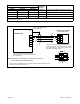
GM95546
1. TB3 HVAC relay connections
2. TB1 connection for current transformer (CT)
3. TB2 120 VAC input connection
4. TB2 connections to customer-supplied power relays
(max 4 relays)
5. P10 RDC2/DC2 controller interface RBUS connections
6. P11 jumper (factory-installed across 2 and 3 for load
management)
4
1
5
2
3
6
Figure 2-18 Combined Interface/ Load Management
Board Customer Connections
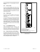
12. Connect HVAC loads to TB3. See Figure 2-18.
Note the priorities of HVAC A and HVAC B relative
to Loads A through D. See Figure 2-19 and
Section 2.7.3.
The air conditioner control scheme requires
splicing into the existing building low voltage wiring
from the thermostat to the air conditioner/furnace.
In a typical four wire scheme, connect the cooling
wire (Y) in series to the respective terminal block on
the load shed kit.
13. Record the names of the loads connected to each
relay in Figure 2-19. For example, Load A may be
a sump pump, and HVAC A may be the air
conditioner.
Note: If the OnCuer Plus Generator Management
System is used, the load descriptions can be
changed remotely. For instructions, see
TP-6928, OnCue Plus Operation Manual.
To avoid confusion, make sure that the load
description matches the equipment
connected to the corresponding relay.
14. Install the ATS enclosure cover.
15. Check that the generator set is OFF.
16. Reconnect the utility power to the transfer switch.
17. Reconnect the generator set engine starting
battery, negative (--) lead last.
18. Reconnect utility power to the generator set.
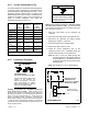
Priority Relay Record the Load Description
1 Load A
2 HVAC A
3 Load B
4 Load C
5 HVAC B
6 Load D
Note: Priority 1 (Load A) adds first and sheds last.
Figure 2-19 Load Priority and Descriptions