
RXT Transfer Switch Manual


TP-6807 1/16 27Section 2 Installation
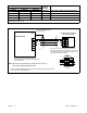
8. Connect RBUS communication cable to the
combined interface board: Connect the generator
controller’s interface connection to A, B, PWR, and
COM on terminal block P10 on the interface/load
management board. See Figure 2-20. See
Section 2.6 for detailed RBUS connection
instructions.
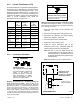
9. Follow the instructions in TT-1574, provided with
the LCM, to connect the load control module.
a. Connect the LCM RBUS connections to either
the combined interface board or to the
generator’s RDC2 or DC2 controller.
b. Connect the current transformer (CT) to the
LCM. Do not connect the CT to the combined
interface board in the RXT enclosure.
c. Connect power relays, HVAC connections, and
120 VAC power to the LCM as described in
TT-1574.
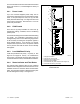
10. Install the ATS enclosure cover.
11. Check that the generator set is OFF.
12. Reconnect the utility power to the transfer switch.
13. Reconnect the generator set engine starting
battery, negative (--) lead last.
14. Reconnect utility power to the generator set.
1
1. P11: Install jumper across pins 1 and 2 to disable load
management
2. Connect RBUS communication cable to P10 on the
combined board.
Note: DO NOT connect power relays, HVAC relays, or
current transformer to the combined board.
Connect to the LCM as described in the LCM
instruction sheet.
GM90773
2
DO NOT
CONNECT
TB2: DO NOT CONNECT
Figure 2-20 Combined Interface/ Load Management
Board Connections with LCM