
RXT Transfer Switch Manual


TP-6807 1/1628 Section 2 Installation
2.9 Optional Load Control
Connection
Connector P11 on the standard interface module
provides a connection point for optional load control
circuits. The load control contact provides a delayed
contact closure to allow startup of selected loads 5
minutes after transfer to the emergency power source
(generator set). Use this contact to delay startup of
equipment with large motor-starting loads such as air
conditioners.
See Figure 2-21 for the location of load control
connector P11. See Figure 2-22 for contact ratings,
connection, and wire size information.
Note: For load add and load shed operation based on
generator capacity, use the load shed kit or the
combined interface/load management board.
See Sections 1.4.2, 2.7, and 3.4 for more
information about load management.
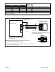
1. Load control connection P11
GM80663
1
Figure 2-21 Load Control Connection, Standard
Interface Board
2.10 Accessory Module
Connections
For connection of the optional programmable interface
module (PIM), refer to the instructions provided with the
module and to the generator set installation manual.
2.11 Test and Exercise
Refer to the generator set Operation Manual for
instructions to test the power system operation and to
set the RDC2 or DC2 controller for weekly exercise runs
to keep the power system in good operating condition.
2.12 Warranty Registration
Startup Notification Form. The Startup Notification
Form covers all equipment in the standby system.
Complete the Startup Notification Form and register the
equipment in the Kohler online warranty system within
60 days of the initial startup date.
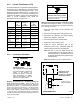
Terminal Block Connection Designation Description Contact Rating Wire Size
P11
P11-1 LC1
Load Control Output
10 A @ 250 VAC
1A@30VDC
#12--18 AWG
P11-2 LC2
Figure 2-22 Load Control Contact P11 Connections