
RXT Transfer Switch Manual


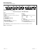

Table of Contents
TP-6807 1/16 Table of Contents 3
Product Identification Information 2.............................................................
Safety Precautions and Instructions 5.........................................................
Introduction 7...............................................................................
List of Related Literature 8.....................................................
Nameplate 8.................................................................
Model Designation 9..........................................................
Service Assistance 10.........................................................................
Section 1 Description 11......................................................................
1.1 Transfer Switch Description 11.............................................
1.2 Service Entrance Models 11...............................................
1.3 Load Centers 11.........................................................
1.4 Controller Interface Board 12...............................................
1.4.1 Standard Interface Board 12.......................................
1.4.2 Combined Interface/Load Management Board 12.....................
1.5 Optional Status Indicator Panels 14.........................................
1.5.1 Standard Status Indicator Panel 14.................................
1.5.2 Status Indicator Panel for Combined Interface/ Load Management Board . .
14
Section 2 Installation 15......................................................................
2.1 Introduction 15...........................................................
2.2 Receipt of Unit 15........................................................
2.2.1 Inspection 15....................................................
2.2.2 Storage 15......................................................
2.2.3 Unpacking 15....................................................
2.2.4 Lifting 15........................................................
2.3 Installation 16............................................................
2.4 Manual Operation Check 17...............................................
2.4.1 Manual Operation Procedure 1 17..................................
2.4.2 Manual Operation Procedure 2 17..................................
2.5 Electrical Wiring 18.......................................................
2.5.1 Load Center Circuit Breakers 19....................................
2.5.2 AC Power Connections 19.........................................
2.5.3 Neutral Connection 19............................................
2.5.4 Neutral Bonding Jumper, Service Entrance Models 19.................
2.5.5 Engine Start Function 19..........................................
2.6 Interface Module Connection 20............................................
2.7 Combined Interface/Load Management Board 22.............................
2.7.1 Relay Modules 22................................................
2.7.2 HVAC Loads 22..................................................
2.7.3 Load Add/Shed Priority 22.........................................
2.7.4 Current Transformers (CTs) 23.....................................
2.7.5 Connection Procedure 23..........................................
2.8 Load Control Module (LCM) 26.............................................
2.8.1 LCM with Standard Interface Board 26..............................
2.8.2 LCM with Combined Interface Board 26.............................
2.9 Optional Load Control Connection 28.......................................
2.10 Accessory Module Connections 28.........................................
2.11 Test and Exercise 28
......................................................
2.12 Warranty Registration 28..................................................