
RXT Transfer Switch Manual


TP-6807 1/1630 Section 3 Operation
For more information about the load add and load shed
timing, see Section 3.5, Load Management Theory of
Operation.
3.4.1 Power Loads
Up to four customer-supplied power relays can be
connected for management of non-essential secondary
loads. If two-pole relays are used, two (2) 120 VAC
loads (shed simultaneously) or a single 240 VAC load
can be wired to each relay. See Section 2.7.1 for more
power relay information.
3.4.2 HVAC Loads
There are two (2) relays available to control two (2)
independent heating, ventilation, and air conditioning
(HVAC) loads.
A 5-minute time delay prevents HVAC loads from adding
too quickly. Air conditioning compressors may be
damaged if they start too soon after being stopped due
to the necessity of starting the compressor against a
large residual pressure. Five minutes is a typically
accepted time required for an AC compressor to bleed
off to a pressure level that the motor can successfully
start against.
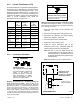
3.4.3 Load Add/Shed Priority
Loads are prioritized from priority 1 to priority 6. See
Figure 2-19 on page 25. Priority 1 is considered the
most critical; it will add first and shed last. Priority 6 is
considered the least critical; it will add last and shed first.
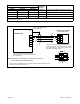
3.4.4 Status Indicator and Test Button
The optional status indicator panel for the combined
interface/load management board includes the source
available and source connection LEDs and load status
LEDs. The panel also includes a Test button that cycles
the load management relays. See Figure 3-2.
1
GM90763
1. Utility power available
2. Utility source supplying load
3. Generator source supplying load
4. Generator power available
5. Load add/shed relay status indicators (see Figure 3-3)
6. Load shed test button (cycles relays)
2
3
4
5
6
Figure 3-2 Optional Status Indicator Panel for
Combined Board