
RXT Transfer Switch Spec Sheet
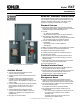


G11-140 (Model RXT Automatic Transfer Switch) 3/20g Page 3
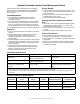
Optional C ombined Interface/Load Management Board
The RXT transfer switch is available with either a standard
interface board or a combined interface/load management
board. The combined board allows load management as
described below.
Load Management
D The combined load management board disconnects
non-critical loads to prevent generator overload, in
compliance with NEC.
D The combined load management board monitors generator
current and frequency to determine when to add or shed
loads. This monitoring prevents frequency drops that can
damage valuable electronics like computers and televisions.
D Load management allows the use of a smaller generator set.
Operation
D Loads are automatically added or shed based on generator
capacity.
D The load control system uses dynamic logic to prevent
shedding important loads unnecessarily when air
conditioning, refrigerator, or water pump motors start
(patent pending).
D The load management board and generator communicate to
provide smart power management. The time to shed loads
decreases as each load is shed to quickly adapt to critical
power requirements.
D Load shed power level and frequency setpoints can be
adjusted using a personal computer (laptop) and Kohlerr
SiteTecht software, which is only available to Kohler-
authorized distributors and dealers.
Priority Setting
D Loads are added and shed according to their priority. Load 1
is the top priority, which is added first and shed last. Load 6
is the lowest priority.
D Less critical loads can be turned off automatically when
essential appliances are running.
D Load priorities are hard-wired at installation.
Viewing Load Shed Outputs with OnCuer
Plus
D Use Kohler’s OnCuer Plus Generator Management System
(sold separately) to view load status (On or Off) for loads
connected to the load shed relays.
D Use OnCuer Plus to remotely monitor when loads are shed
or added.
D The load shed outputs can be labeled in OnCuer Plus.
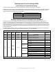
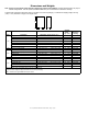
Current Transformer
D The combined load management board option includes a
400 amp current transfomer (CT) for load monitoring.
D A larger diameter CT is available for applications that require
larger cables.
D A 500 amp CT is available for use with a 60RCL generator.
D See the table below for current transformer specifications
and optional kit numbers.
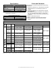
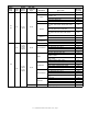
Load Shed Specifications
Connection Rating Connection
Pilot Relays*
125VAC, 10 A total (general purpose)
120VAC, 125VA (pilot duty)
#12- 20 AWG
HVAC Relays (qty. 2)
125VAC, 10 A (general purpose)
120VAC, 125VA (pilot duty)
#12- 20 AWG
RBUS Communication and Power
Connections to the RDC2/DC2
controller
0.5 A @ 12 VDC
Use Belden #9402 or equivalent 20 AWG
shielded, twisted-pair communications
cable [
* Four (4) pilot relays are provided for customer-supplied normally closed load-switching contactors/relays. The combination of four load relay
outputs cannot exceed 10 amps total current draw. Kohler
r power relay modules are recommended.
[ For long distances, use an equivalent shielded, twisted-pair cable for RBUS connections and individual 12- 20 AWG wires (qty. 2) for power
connections.
Current Transformer Specifications
Ratio
(Amps:VAC)
Outer Diameter
mm (in.)
Inner Diameter
mm (in.)
Service Part
Number
Sales Kit Part Number CT Availability
400:3 63.5 (2.5) 28.7 (1.13) GM83929 N/A
Included with combined
board
400:3 111.8 (4.4) 57.2 (2.25) GM17250 GM17250-KP1-QS Sold Separately
500:3 171.5 (6.75) 108.0 (4.25) GM60264 GM17250-KP2-QS
Sold Separately
(use with 60RCL)