
RXT Transfer Switch Spec Sheet
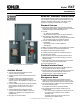


G11-140 (Model RXT Automatic Transfer Switch) 3/20g Page 7
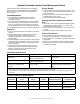
Accessories
- Auxiliary position-indicating contacts
D One closed on normal position and one closed on emergency
position
D Form C contacts rated 15 A @ 250 VAC
- Power relay modules
D 50 amp DPST power relay mounted in a NEMA type 3R
enclosure
D Use up to four modules with the combined interface/ load
management board
D UL/cUL listed
D Dimensions: 172 x 233 x 92 mm (6.8 x 9.2 x 3.6 in.)
D For more information, see specification sheet G6-143
- Status indicator kit for standard interface board
D LEDs indicate normal and emergency source availability
and contactor position
D Mounts on the outside of the RXT enclosure
D View transfer switch status without removing enclosure
cover
D An overhang on the enclosure protects the indicator
panel and ribbon cable opening
D Dimensions: 92 mm x 42 mm (3.62 in. x 1.65 in.)
D Connects to the standard interface board only
D For more information on the status indicator kit, see
specification sheet G11-123
- Status indicator kit for combined interface/ load
management board
D LEDs indicate normal and emergency source availability
and contactor position
D Dual color LEDs for each load indicate load status
(powered or shed) and flash during a test
D Load shed test button allows the operator to cycle the
load shed relays in order of priority (when generator is in
RUN mode)
D Mounts on the outside of the RXT enclosure
D View transfer switch and load status without removing
enclosure cover
D An overhang on the enclosure protects the indicator
panel and ribbon cable opening
D Dimensions: 183 mm x 42 mm (7.20 in. x 1.65 in.)
D Connects to the combined interface/ load management
board only
D For more information on the status indicator kit, see
specification sheet G11-123
- Auxiliary circuit breaker (service entrance models only)
D 15 amp single-pole type QO circuit breaker
D Mounts on a bracket inside the enclosure
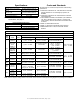
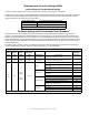
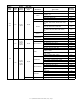
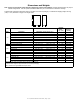
Available Models
All Model RXT transfer switches are standard-transition 60 Hz automatic transfer switches. Letters in parentheses refer to the
model designation code described on the last page.
Am
p
s
Description
(Connections)
Voltages
Poles Phases
WCR w
RMS S
y
mmetrical Am
p
s
208 (C) 240 (F) 480 (M)
100
Standard (A)
D
2(N) 1 10,000
Standard, with 16-space load
center (B) W
D
2(N) 1 10,000
Standard, with 12-space
load center **
D
2(N) 1 10,000
Service entrance (ASE, CSE)
D
2(N) 1 22,000
Standard, 3-phase (A)
D D D
3(T)or4(V) 3 30,000
150 Service entrance (ASE)
D
2(N) 1 22,000
200
Standard (A)
D
2(N) 1 10,000
Service entrance (ASE, CSE)
D
2(N) 1 22,000
Standard, 3-phase (A)
D D D
3(T)or4(V) 3 30,000
300 Service entrance (ASE)
D
2(N) 1 35,000
400
Standard (A)
D
2(N) 1 50,000
Service entrance (ASE)
D
2(N) 1 35,000
Standard, 3-phase (A)
D D D
3(T)or4(V) 3 50,000
w Withstand and close-on rating. See pages 3-5 for WCR information and specific breaker ratings.
W With 16-space load center and NEMA 1 or NEMA 3R enclosure. Up to 8 tandem breakers can be used, for a maximum of 24 circuits.
** GM85273- SA_ with 12-space load center and NEMA 1 enclosure.
Note: Combined interface board is available on single-phase standard or service entrance models. (Not available on 3-phase or load center models.)