24-pin Dot-matrix Printer ACCEL-7350 HANDBOOK
ALLEL-7350 HANDBOOK
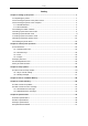
Catalog Catalog Chapter 1 Setting up the printer ................................................................................................ 1 1.1 Unpacking the printer........................................................................................................... 1 1.2 Connecting the printer to the power source ......................................................................... 2 1.3 Connecting the printer to the computer...............................................................
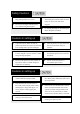
Safety Cautions Do not touch the print head immediately after printing because it is too hot. Do not put your finger under the tractor cover while loading fanfold paper. Use two hands and hold firmly at each end when lifting the cut sheet feeder. Personal injury can occur if the ASF unit is dropped. Do not put your finger on the tractor gear, when using the rear tractor. Cautions in setting up Unpack the printer.
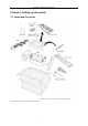
Chapter 1 Setting up the printer Chapter 1 Setting up the printer 1.1 Unpacking the printer *Remove lever, fixed on the bottom side of Paper rack. The packing style is subject to change without notice.
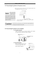
Chapter 1 Setting up the printer 1.2 Connecting the printer to the power source • Make sure that the power switch is set to off. Connect the printer with the supplied power cable to an AC outlet Once the printer is turned off, wait for three seconds or more before turning it on again. If the printer is turned on again within three seconds after turning it off, it may malfunction due to an initialization failure.
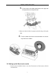
Chapter 1 Setting up the printer 1.4 Installing the ribbon cassette 1. Turn off the power. Open the front cover. Move the print head to the left end position. Caution 2. Do not touch the print head immediately after printing because it may be too hot. Remove the Red Fixing Material located at the center of the ribbon cassette, attach the cassette, as shown below.
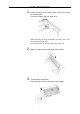
Chapter 1 Setting up the printer 3. Fit the holes in the ribbon attachment to the right and left projections on the print head. • Make sure that the ribbon is properly under the edge of the print head. 4. Turn the ribbon feed knob counterclockwise to remove any slack in the ribbon. 1.5 Setting up the Rear tractor mode • Tractor can be installed in front or rear side; Front tractor or Rear tractor, called in the hand book.
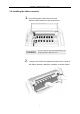
Chapter 1 Setting up the printer 1. Attach the paper rack holders (right / left) to the printer as shown below. Press the holders until you hear click. When removing the paper rack holder, use there move lever, screwed on the paper rack. See the instruction on the rear side of the paper rack. 2. Attach the paper rack to the paper rack holders. 3. Put the paper rack down. Press the paper rack on the paper rack holders.
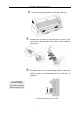
Chapter 1 Setting up the printer 4. Move the both paper guides to the right / left end. 5. Connect the connector on the left side of tractor to the connector on the rear side of the printer. Then install the rear tractor. 6. The both tractors can be moved right and left to meet the width of paper or printing data when the lock lever is released. CAUTION Do not put your finger under the tractor cover • Set fanfold paper onto the tractors.
Chapter 1 Setting up the printer 7. Slide the paper path lever to the symbol or the position of "AUTO". The lever position should be at "AUTO" when using the printer driver. 8. Specify the page length. Fanfold paper size marked on package (Example) Specify the page length referring the number of sprocket holes on the paper in case that the paper length can not be specified. No. of holes x 0.5 inch equals to the page length. The 8 of holes on the above mean that this fanfold is 4 inches in length.
Chapter 1 Setting up the printer 9. Perform the trial printing after connecting the printer to the computer. Adjust the tractors to find a correct position in case that the printing is tilted to right / left. In case of tilting vertically the printing start position should be adjusted by “4 TOF ADJUST”. 1.6 Setting up the Manual mode 1. Attach the paper rack holders (right / left) and the paper rack. See the item No. 1-3 on the page 1-5. 2.
Chapter 1 Setting up the printer 3. Slide the paper path lever to the symbol or the position of "AUTO". The lever position should be at "AUTO" when using the printer driver. 4. Connect the printer to the computer and perform a trial printing. The display appears as below along with the sound of buzzer when the printer receives the data from the computer. 5. Insert a cut sheet paper straight along the paper guide. If a paper is inserted on the skew, the printer detects it.
Chapter 1 Setting up the printer If a paper is inserted on the skew as the upper left of the paper is over the paper guide, the printer may not adjust the skew. In this case, move the paper guide to the left a little, then insert the paper at some distance from the paper guide. Note In case of tilting vertically the printing position should be adjusted by “5 TOF ADJUST”. When printing a book, set BOOK at #10 PAGE LENGH NOTE BOOK. 1.7 Setting up the Front tractor mode 1.
Chapter 1 Setting up the printer 2. Connect the connector on the left side of tractor to the connector on the front side of the printer. 3. Attach the tractor to the paper rack holders as shown below. 4. Attach the paper rack to the paper rack holders.
Chapter 1 Setting up the printer 5. The both tractors can be moved right and left to meet the width of paper or printing data when the lock lever is released. • Set fanfold paper onto the tractors. 6. Put the paper rack down. Press the paper rack on the paper rack. 7. Slide the paper path lever to the symbol or the position of "AUTO". The lever position should be at "AUTO" when using the printer driver.
Chapter 1 Setting up the printer 8. Specify the page length. Check the fanfold paper size marked on the package. 9. Perform the trial printing after connecting the printer to the computer. Adjust the tractors to find a correct position in case that the printing is tilted to right / left. In case of tilting vertically the printing start position should be adjusted by “3 TOF ADJUST”. When using the front tractor along with the CSF, cut the fanfold paper by hand, not by the paper cutter.
Chapter 1 Setting up the printer 1.8 Setting up the ASF (option) mode 1. Attach the paper rack holder (right / left) and the paper rack. See the item No. 1-3 on the page 1-5. 2. Move the both paper guides to the right / left end. 3. Attach the hoppers and center support to the cut sheet feeder.
Chapter 1 Setting up the printer 4. Attach the cut sheet feeder to the back of the printer. ASF CAUTION Use both hands and hold firmly at each end when lifting the cut sheet feeder. Personal injury can occur if the ASF unit is dropped. 5. Shuffle the paper as show below.
Chapter 1 Setting up the printer Note Be sure to shuffle sheets sufficiently before setting them. Otherwise, several sheets of paper may be fed at the same time resulting in a paper jam. 6. Turn the ASF release levers to the front to release the paper bin. ASF release lever 7. Turn the paper guide lock lever to the Release position to adjust the paper width. Turn the paper guide lock lever to the Lock position.
Chapter 1 Setting up the printer 8. Move the ASF release levers to the back to fix the paper bin. 9. Slide the paper path lever to the symbol or the position of "AUTO". The lever position should be at "AUTO" when using the printer driver. 10. Perform the trial printing after connecting the printer to the computer. In case of tilting vertically the printing start position should be adjusted by “6 TOF ADJUST”.
Chapter 1 Setting up the printer Remove the paper rack holder when storing the printer. 1.9 Installing the printer driver For the details of the printer driver, please consult the file ”Installation Guide.txt” on the packed Driver-CD.
Chapter 2 Control panel operation Chapter 2 Control panel operation 2.1 Control Panel The liquid crystal display (LCD) on the control panel displays the processing conditions of the printer and the setting of the functions. The keys on the control panel provide various functions. 2.1.
Chapter 2 Control panel operation 2.1.2 Function keys 1. ONLINE Press the ONLINE key to change the printing enabled (online) state and printing disabled (offline) state. 2. RESET (ALT + ONLINE keys) Press the ONLINE key for two seconds or more while you press the ALT key, a buzzer will sound. Then “INITIAL” is displayed on the LCD if the keys are released. The printer is reset immediately. 3. SPEED Press the SPEED key to display the currently selected printing quality on the LCD.
Chapter 2 Control panel operation 7. ALT The following functions are executed by pressing the corresponding key while you press the ALT key. TEAR OFF→ FF LF/FF → MICRO LF RLF → MICRO RLF HIGH IMPACT → MENU SPEED → RESET 8. TEAR OFF Press the TEAR OFF key, and the printer automatically feeds the perforation of the paper to the paper cutter position (for fanfold paper only). If the perforation is not adjusted to the cutter position, correct the position with the MICRO LF or MICRO RLF key.
Chapter 2 Control panel operation 9. EJECT/LOAD ● ● ● ● If the EJECT/LOAD key is pressed when fanfold paper is loaded, the paper is fed back to the parking position. When it is pressed when a cut sheet paper is loaded, the paper is ejected. When the EJECT/LOAD key is pressed when fanfold paper is at the parking position, the paper is loaded to the TOF position. When the EJECT/LOAD key is pressed with no paper in the manual mode, the key is ignored.
Chapter 2 Control panel operation 2.1.3 LCD Current paper path and the setup memory No. are displayed. Front tractor Manual Rear tractor ASF ASF NOTE NOTE 2.1.4 Lamps ONLINE (Green) ON: Printing is enabled. OFF: Printing is disabled. Blinking: The cover is open, or the printer is in the head temperature protect mode. SPEED (Green) ON: Speed printing. OFF: Normal speed printing. ERROR (Amber) ON: No paper is detected or other operational error occurred. OFF: No error is detected.
Chapter 2 Control panel operation 2.2 Paper path lever The lever for changing the paper path. Position Paper path Note Manual Rear tractor ASF The required paper path can be selected by the setting of the lever. The paper path command is valid when selecting the “AUTO”. The lever position should be at “AUTO” when using the printer driver. Before changing the paper path, remove the paper inside the printer by pressing the EJECT/LOAD key.
Chapter 2 Control panel operation 2.3 Head adjustment lever This lever is for adjusting the gap between the print head and the paper. AUTO 7 1 The lever position should be at "AUTO " normally, which adjusts the gap in accordance with the SETUP MODE. When " AUTO " is selected on the panel, the printer measures the paper thickness and adjusts the gap between the print head and the paper automatically. In case that the graduation 1 - 7 is selected, the gap between print head and paper is fixed.
Chapter 3 Setup options Chapter 3 Setup options 3.1 How to use the setup modes The printer has setup modes, i.e., function setting modes that are unique to this printer. The setup modes enable various printer functions to be set up with the function keys on the operation panel. This section provides an the outline of the setup modes and the details of the setup functions. For the details of the setup modes, see the Owner’s Manual in the packed Driver-CD. 3.1.1 Keys used for setting 1.
Chapter 3 Setup options 3.1.2 Setting example The following is the example to change the page length of fanfold paper from 11 to 8 inch. 1. Press the MENU key while depressing the ALT key. + 2. Select #7 with the 3. Press the key. 4. Press the or or key. key to display "8 INCH" on the LCD. 5. Press the ENTER key. "8 INCH" is marked with on asterisk. 6. Press the MENU key. The setting is automatically saved and the printer is initialized.
Chapter 4 How to use SETUP Memory Chapter 4 How to use MENU Memory This printer has total 6 types of MENU Memory 1 - 6. Various MENU stated in the chapter 3 can be memorized in every memory. The memory type in current operation is normally indicated with the number on the LCD as shown below. Å Indicating that the printer is operated at the mode of MEMORY 1. The MENU memory is changed by pushing the FORMAT key. If pushing the key first.
Chapter 5 Troubleshooting Chapter 5 Troubleshooting 5.1 How to solve the problem 1. Printing speed is slow. Push the key SPEED and select the mode High-speed. LQ NORMAL HIGH SPEED 2 HIGH SPEED 1 2. Printing is light. Check the condition of ribbon cassette. If the surface of fabric becomes whitish, replace the cassette with a new one. Head Adjustment may not be adequate. Adjust the setting of #1 HEAD ADJUSTMENT. When a multipart form are used for printing.
Chapter 5 Troubleshooting 6. The paper sensor does not detect paper. (The print start position of paper tilts downward) The detection capability of the sensors may not be adequate level. Perform the EEPROM Initialization 2. (See page 5 - 3) 7. Out-of-paper can not be detected. In case that the printing is continued even when the paper is out, the setting may not be adequate. Make sure of the paper size, the page length on MENU and the format of the printing data.
Chapter 5 Troubleshooting The message is displayed on the LCD and returns to the normal display after the initialization 1. • EEPROM Initialization 2 The learning of the sensors switching position is performed. The settings in the MENU mode are not changed. [Procedure] Set 15-inch fanfold paper to the rear tractors. Keep the SPEED and TEAR OFF keys depressed and turn on the printer. After confirming the paper setting, press the ENTER key. When the message is displayed, press the MENU key.
Chapter 5 Troubleshooting 5.2.2 Operational error message • The print head is being cooled to prevent it from overheating. The ONLINE lamp blinks. The print head has become too high-density printing. When this displayed, the printing speed is printing stops. When the print head drops, the printer restarts printing. hot during message is reduced or temperature • This error message indicates that fanfold paper is not fed back to the packing position properly. Cut the paper to remove it.
Chapter 5 Troubleshooting A paper jam occurs at the front tractor. Pull the ejected paper outward gently and press the ONLINE key to restart printing. When the PAPER JAM still remains, remove all paper and reinstall the paper into the tractor properly and press the ONLINE key. Re-adjust the gap between the print head and the paper, by #1 HEAD ADJUSTMENT. When the paper thickness may be not constant, set YES at #49 LF STABLE.
Chapter 5 Troubleshooting • This error occurs if the front cover is opened. The ONLINE lamp blinks. Closing the front cover will remove the cause of this error. The printer is in the offline state while the cover is opened. CAUTION Never open the front cover during printing. Press the ONLINE key to stop printing and then open the front cover. • The jam sensor is defective when loading fanfold paper. Press the ONLINE key to recover the printer from this error.
Chapter 6 Specifications Chapter 6 Specifications 6.
Chapter 6 Specifications 6.2 Other specifications Power supply AC 120 V, 60Hz (USA and Canada) AC 220-240V, 50-60Hz (Europe and Asia) Power consumption Draft self 170watts 2.3A (120VAC) 1.3A(220-240VAC) Stand-by 40watts 0.6A (120VAC) 0.4A(220-240VAC) Operating temperature Operating humidity Dimensions Weight Energystar 15watts 5 to 40℃(41 to 104 ℉) 20 to 80% (No condensation) 635mm(W) x 465mm(D) x 294mm(H) 22kg 6.3 Paper specifications Available paper size • Fanfold paper Paper width 203.
Chapter 6 Specifications 6.
FCC NOTE: The manufacturer is not responsible for any radio or TV interference caused by unauthorized modifications to this equipment.