CHROMA METER CS-200 Instruction Manual
Safety Symbols The following symbols are used in this manual to prevent accidents which may occur as a result of incorrect use of the instrument. Denotes a sentence regarding a safety warning or note. Read the sentence carefully to ensure safe and correct use. Denotes a prohibited operation. The operation must never been performed. Denotes an instruction. The instruction must be strictly adhered to. Denotes an instruction. Disconnect the AC adapter from the AC outlet. Denotes a prohibited operation.
Safety Precautions To ensure correct use of this instrument, read the following points carefully and adhere to them. After you have read this manual, keep it in a safe place where it can be referred to anytime a question arises. (Failure to adhere to the following points may result in death or Warning serious injury.) Do not use this instrument in places where flammable or combustible gases (gasoline etc.) are present. Doing so may cause fire.
Should this instrument or AC adapter be damaged or smoke or odd smell be generated, do not keep using such instrument or AC adapter without correction. Doing so may cause fire. In such situations, switch power off immediately, unplug AC adapter (or remove batteries in using ones) and contact the nearest KONICA MINOLTA SENSING authorized service facility. Do not look at sun or intense light through finder of this instrument. This may lose your sight.
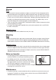
Introduction This chroma meter realizes high-precision measurement of luminance and chromaticity comparable to spectroradiometers by the employment of newly developed spectral fitting method. Carefully read this manual before using one. Packaging material Retain accompanying packaging materials (carton, protector, and plastic bag) and holding cap (CS-A24) supplied as standard accessory for future usage. This is delicate measurement instrument.
This Instrument • Do not subject this instrument to strong impact or vibration. • Do not forcibly pull, bend, or apply strong force to power cord for attached AC adapter or USB cable. This may result in snapping. • Connect this unit to power source with minimal noise. • Should breakage or abnormality be found during operation, switch power off immediately and unplug. Then refer to "Error Check" on page 111. • Should this instrument break down, do not try to disassemble and repair it by yourself.
Storage Body • Do not store this instrument under direct sunlight or near heater. The internal temperature of this instrument to becomes much higher than ambient temperature which may break this instrument. • Store this instrument at ambient temperature between 0 and 40˚C and relative humidity 85% or less (at 35˚C) with no condensation. Storage under high temperature and humidity may deteriorate performance of this instrument.
INDEX Safety Precautions …………………… 2 Installing Introduction …………………………… 3 Installing ……………………………… 20 Note on Use …………………………… 3 Operating Environment ……………………… This Instrument ……………………………… Backup Battery ……………………………… Objective and Close-Up lenses (Optional) Recommended batteries …………………… Hand Strap …………………………… 21 3 4 4 4 4 Adjusting hand strap ……………………… 21 How to carry………………………………… 21 Notes on carrying ………………………… 21 Connecting AC Adapter …………… 22 Storage…………………………………… 5 Connection Method …………………… 2
Buzzer Setting ………………………… 52 Backlight ON/OFF …………………… 54 Communication Setting Sleep Mode ………………… 56 Connecting to PC …………………… 98 Setting Internal Clock ……………… 58 Remote Mode ………………………… 99 Measurement Preparation Description Calibration …………………………… 62 Principle of Measurement Calibration Channel …………………… 62 Spectral Fitting Method …………… 102 User Calibration ……………………… 63 LvT∆uv ……………………………… 103 Implementing User Calibration …… 64 Dominant Wavelength …………… 104 (1) Through measurement …………… 66
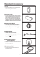
Standard Accessory Lens Cap • Attached to objective lens for protecting it when not using this instrument. Holding Cap CS-A24 • Prevents measuring angle selector position from deviating during transfer. Remove one when using this instrument and store not to lose. Do not fail to set measuring angle selector at center 0.2˚ for transfer before attaching this holding cap to measuring angle selector. ND Eyepiece Filter CS-A27 • Eases glare when peeping into finder to measure high luminance object.
Optional Accessories Close-Up lens No.107 Close-Up lens No.122 • Placed before objective lens for measurement of small object. ND Filter (1/10) CS-A6 ND Filter (1/100) CS-A7 • Placed before objective lens for measurement of high luminance object, but sandwich step up ring (40.5 to 55 mm) CS-A26 inbetween. Calibration Certificate (For ND Filter) • Calibration certificate is available for ND filters (1/10) CS-A6 and (1/100) CS-A7. Step Up Ring (40.
Soft Case CS-A23 • Used to keep this instrument and accessories or carry them with hand. Never use for transfer. Data Management Software CS-S10w Professional • Enables multiple data management thanks to additional functions to that for CS-S10w Standard.
System Configuration Standard accessories Optional accessories Lens Cap Step Up Ring (40.5-55mm) CS-A26 AA-Size Batteries (x4) (commercially available) Angle Finder VN Adapter ( including ) and Case. CS-200 ND Filter (1/10)CS-A6 (1/100)CS-A7 ND Eyepiece Filter AC-A27 TARGET COLOR PEAK/VALLEY SHUTTER MEMORY KEY LOCK MEAS SPEED CHAR MODE ABS/DIFF BACKLIGHT RECALC SHIFT MENU ESC ENTER AC Adapter AC-A23 Close-Up Lenses No.107 No.
Names and Functions of Parts Names of Each Part LCD screen Focus distance scale Objective lens Key panel Power switch AC adapter input terminal Focus adjustment ring USB connector Measuring angle selector Protect cover Finder Measurement button Diopter adjustment ring Hand strap Inside Finder Screw hole for fixing Aperture battery chamber cover in-finder indicator 12
Functions of Each Part Power switch:(p.23) Switches this instrument on/off. (|) for ON; (O) for OFF AC adapter input terminal:(p.23) To which accessory AC adapter is connected. USB connector: (p.98) To which USB cable is connected when used with PC. Measuring angle selector: (p.88) Used to select measuring angle among 1˚, 0.2˚ and 0.1˚. Protect cover: (p.23,98) Protects AC adapter input terminal and USB connector. Objective lens: Directed to object for measurement. Focus adjustment ring: (p.
Key Panel 1 5 2 1 2 6 5 3 4 3 6 4 8 7 8 Main Functions of Each Key ①MEMORY Measured data is stored in memory by pressing this key when measurement screen and save screen appears. ②MEAS SPEED Measurement time is switched in order AUTO → LTD. AUTO → Super-FAST →FAST → SLOW → Super-SLOW → MANUAL → AUTO if pressed when screen with which measurement is available.(p.
SHIFT mode Press ➎ SHIFT key to switch between SHIFT mode and normal mode. In SHIFT mode, keys from ➊ to ➍ , ➏ and ➑ become valid; in normal mode, keys from ① to ④, ⑥ and ⑧ become valid. Keys of ⑤, ⑦ and ➎ are always valid either in SHIFT mode or normal mode. ➊TARGET To go to target value setting screen from either measurement or save screen. ➋ COLOR If pressed when screen with which measurement is available, color space is switched in order of Lvxy →Lvu'v' → LvT (d)uv → XYZ →dominant wavelength →Lvxy.
Indicator Inside Finder 1˚Aperture Lv value appears on in-finder indicator. 0.2˚ Aperture K (displayed as ) and M (displayed as ) show x103 and x10 6 respectively. 0.
Diopter Adjustment Rotate diopter adjustment ring for adjustment of diopter. Diopter adjustment ring Adjust so that A or B on aperture or black circle indicating measuring area looks clear when observing object through finder. Adjustment would be easy starting with 1˚ aperture where object near aperture looks blur. A Make sure to adjust diopter before measurement. Diopter should be adjusted for the eyesight of the person who will be taking measurement.
Installing Setting status in this instrument is displayed. Currently selected measuring angle is displayed.(1°,0.2°,0.1°)(p.88) Currently selected measuring time is displayed.(AUTO,LTD.AUTO, S-FAST, FAST, SLOW, S-SLOW, MANU)(p.28) Synchronization frequency is displayed when internal sync measurement mode is set; NO SYNC is displayed when it is not set.(p.30) Currently selected lens type is displayed .(STANDARD,No.107,No.122)(p.
Installing 19
Installing Installing Use screw hole for fixing at the bottom of this instrument if utilized with tripod or jig. 2 type holes are available. Tripod screw hole : To set on tripod. Screw depth is 6.5 mm. ISO screw hole : To set on jig. Use ISO screw with top diameter of 5mm and depth of 6.5 mm. Standard plane for distance measurements 154 ISO screw Tripod screw Optical axis 61.6 70 150 For other detailed dimensions, see p.109.
Hand strap can be used to carry this instrument with hand. Adjusting hand strap Insert your right hand between this instrument and hand strap, and adjust hand strap so that your hand securely fits to the instrument without any gap. How to carry As shown in the figure, insert your right hand through hand strap and support the bottom close to objective lens with your left hand. Tighten your arms to carry it more securely. Notes on carrying Be careful not to thud this instrument when carrying.
Installing Connecting AC Adapter Either AC adapter(accessory) or 4 AA size batteries(commercially available) can be used as power source of this instrument. Warning (Failure to adhere to the following points may result in death or serious injury.) Always use the AC adapter and power cord supplied as a standard accessory or optional (AC-A23), and connect it to indoor AC outlet of rated voltage and frequency. Failure to follow either of these may result in damage to unit, fire or electric shock.
Installing Connection Method 1. 2. 3. Make sure that power switch is OFF (slided to [O] mark side). Lift protect cover and connect AC adapter plug to AC adapter input terminal on body. Plug AC adapter to outlet (AC 100V-120V or 200-240V , 50 Hz/60 Hz). ■■■■■■■■■■■■ ■■ ■■ ■■ ■■ ■■ ■■■■ ■■■ ■■ ■■■■ ■■■■ ■■ ■■■■ ■■■■■ ■■ ■■■■ ■■■■■■ ■■ ■■ ■■■■■■■ ■■ ■■ ■■ ■■■■■■■■■■■■ Insert AC adapter plug all the way seated in AC outlet. If not, may appear when turning power switch on.
Installing Placing Batteries Warning (Failure to adhere to the following points may result in death or serious injury.) Do not dispose of batteries in fire, short their terminals, apply heat to them or disassemble them. Doing so may cause explosion or liquid leakage, resulting in fire or injury. Should liquid leak from battery and contact to eye, wash liquid off with clean water without rubbing eyes and immediately seek for medical professional's advice.
Installing Placing Batteries 1. 2. 3. Make sure that power switch is OFF (slided to [O] mark side). Open battery chamber cover while pressing and sliding mark to the direction shown in illustration. Place 4 AA size batteries following polarity indication in battery chamber. Do no touch or short terminals in battery chamber. Doing so may cause breakage of this instrument. Use alkaline-manganese, lithium, or nickel-metal-hydride batteries. 4.
Installing ON(|)/OFF(O) of Power Switch To secure accurate measurement in either of following situations, 15-minute warm-up is recommended at least. 1. Measuring low luminance light source object: At 2856K (Standard light source A) as measuring stick 10 cd/m2 or lower (1˚ Aperture) 250 cd/m2 or lower (0.2˚ Aperture) 1000 cd/m2 or lower (0.1˚ Aperture) 2. Outside room temperature and normal humidity ranges Turning power switch ON 1. Slide power switch to ON (|) side.
Setting 27
Selecting Measurement Time Select measurement time depending on purpose. 7 modes are available for measurement time. Select the mode with long measurement time when repeated accuracy is required such as when measuring object of low luminance. Setting ∗ Setting at the shipment from factory : AUTO.
3. Press MEAS SPEED key to select measurement speed. 1° VIEW MANU: 1 >NO SYNC Lv ------cd/m2 <STANDARD AUTO NUM x ----- y ------ CH00: < DEFAULT> switches in order of AUTO → LTD.AUTO SINGLE [ MANU Setting 1° VIEW MANU: 1 >NO SYNC Lv ------cd/m2 <STANDARD MEAS SPEED AUTO NUM x ----- y ------ or < key to set value. key for larger number. If kept pressed, value continuously increases.
Internal Sync Measurement Mode Setting Internal sync measurement mode refers to measurement mode where measurement is made in the same timing as periodical light source pulse frequency, such as vertical synchronization frequency for display. ∗ Setting at the shipment from factory : NO SYNC Operation Procedure Setting SYNC MODE 5, 7 2 1. 3 1, 10 4, 9 Press ESC key when menu or target value setting menu appears. 5 4, 6 1° VIEW AUTO > 60.
5. Press either or key to set arbitrary value. NO SYNC [ OK: [ENTER] CANCEL: [ESC] ] [ 2° ] NO SYNC [ OK: [ENTER] CANCEL: [ESC] ] [ 2° ] Press key to move cursor to second digit position. NO SYNC [ 8. OK: [ENTER] CANCEL: [ESC] ] [ 2°] NO SYNC [ 200.00Hz (SYNC) OK: [ENTER] CANCEL: [ESC] ] [ 2° ]
Setting Observer Color matching function for chromaticity calculation is selectable between 2˚ and 10˚. ∗ Setting at the shipment from factory : 2˚ OBS Operation Procedure Setting OBSERVER 2 1. 3 1, 7 6 Press ESC key when menu or target value setting menu appears. Measurement screen appears on LCD screen. 4, 5 CH00: < DEFAULT> Lv 20.80cd/m2 x 0.4476 y 0.4477 SINGLE [ 2. ] [ 2° ] 1° VIEW AUTO 200.
5.
Selecting Color Space See below table for available color space. ∗ Setting at the shipment from factory : Lvxy Color space LCD Screen Lvxy ∗1 CH00: < DEFAULT > 1° VIEW AUTO 200.00Hz STANDARD AUTO NUM Setting Lv ------cd/m2 x -----y -----MOOO:(NO DATA) SINGLE [ COLOR Lvu’v’ ∗1 ] [ 2° ] CH00: < DEFAULT > [ Lv T ∆uv ∗2 ] [ 2° ] CH00: < DEFAULT > 1° VIEW AUTO 200.
Operation Procedure Setting COLOR 2 1. 3 1 Press ESC key when menu or target value setting menu appears. 1° VIEW AUTO >200.00Hz Lv ------cd/m2 <STANDARD AUTO NUM x ----- y ------ CH00: < DEFAULT> Measurement screen appears on LCD screen. SINGLE [ 2. ] [ 2° ] MOOO:(NO DATA) Lv -----x -----y ------ Press SHIFT to switch to SHIFT mode. [SFT] appears on bottom left of measurement screen.
Selecting Absolute Value (ABS)/Difference (DIFF) Display Whether chromaticity value is shown in absolute (ABS) or difference (DIFF) is selectable. See below table for each case. ∗ Setting at the shipment from factory : Absolute value (ABS) Color Space LVxy ∗1 Switching between Absolute Value (ABS) and Difference (DIFF) Dominant wavelength LV・x・y %LV・∆LV・∆x・∆y Setting CH00: < DEFAULT > 1° VIEW AUTO Lv ------cd/m2 200.
Operation Procedure 3 Setting ABS/DIFF 2 1. 1 Press ESC key when menu or target value setting menu appears. 1° VIEW AUTO >200.00Hz Lv ------cd/m2 <STANDARD AUTO NUM x ----- y ------ CH00: < DEFAULT> Measurement screen appears on LCD screen. SINGLE [ 2. ] [ 2° ] MOOO:(NO DATA) Lv -----x -----y ------ Make sure that [ ] appears on left bottom indicating this instrument has not been set for SHIFT mode.
Selecting Digit for Chromaticity Display This is selectable either 4 or 3. If measurement value on LCD screen is illegible because of blinking, set for 3 digits. ∗ Setting at the shipment from factory : 4 FIGURES Operation Procedure Setting DISPLAY DIGYTS 2 1. 3 1, 7 6 Press ESC key when menu or target value setting menu appears. Measurement screen appears on LCD screen. 5 4, 5 CH00: < DEFAULT> Lv 20.80cd/m2 x 0.4476 y 0.4477 SINGLE [ 2. ] [ 2° ] 1° VIEW AUTO 200.
5. Press ESC key to stop. [
Selecting Lens Type Setting Use optional accessory close-up lens for small area measurement. See instruction manual for close-up lens for the placement of one. If close-up lens is to use, measurement value is required for calibration of lens transmission factor. Since calibration value varies depending on lens type, lens type has to be set in this instrument in advance. Erroneous setting causes incorrect measurement. Below table shows lens to set and setting for this instrument.
3. Menu 2/4 screen appears on LCD screen. [
Selecting Single or Continuous Measurement Here, measurement mode is selectable between “Single measurement” and “Continuous measurement”. Former means one measurement for one press and the latter continuous measurement from one press to another press of any key. In case of “Continuous measurement”, you can also view max and min values during continuous measurement when measurement is completed. ∗ Setting at the shipment from factory : SINGLE Setting Operation Procedure MEAS MODE 2 1.
4. Inversion cursor moves from [MEAS MODE] to right to change measurement mode. [
Selecting of Max or Minimum Value Display Measurement result display is selectable among latest, max and minimum. If max or minimum has been selected here, continuous measurement is to perform even though single measurement has been set. Lv determines max and min values. ∗ Setting at the shipment from factory : latest Setting Operation Procedure PEAK/ VALLEY 2 1. 3 1 Press ESC key when menu or target value setting menu appears. Measurement screen appears on LCD screen.
3. Press PEAK/VALLEY key to show measurement mode to select. CONT. [ SFT ] Latest measurement value also appears on LCD screen in case that or has been selected. 1° VIEW AUTO >NO SYNC Lv 15.61cd/m2 <STANDARD AUTO NUM x 0.4125 y 0.4429 CH00: < DEFAULT> [SFT] Setting for normal screen// shall be retained even after switching OFF (O). [ 2° ] M003: Lv x y 15.61 0.4125 0.
Opening and Closing of Finder Shutter To prevent light from finder from badly influencing measurement, internal shutter of finder is to close for every measurement. If observation through finder during measurement is required, setting can be changed not to close finder shutter. In this case, light from finder needs to be avoided by looking into finder during measurement. ∗ Setting at the shipment from factory : (automatically closes for every measurement) Setting Operation Procedure SUHUTTER 2 1.
3. Press SHUTTER key. 1° VIEW AUTO >NO SYNC Lv 92.74cd/m2 <STANDARD AUTO NUM x 0.4185 y 0.4242 CH00: < DEFAULT> Icon [ ] indicating "automatically closes for every measurement" switches to icon [ ] meaning "always opens" in SHIFT mode. [ ] [ 2° ] 1.04 0.3772 0.3663 CONT. [ 47 ]○ [ 2° ] M003: Lv x y 1.04 0.3772 0.3663 SUHUTTER 1° VIEW AUTO >NO SYNC Lv 92.74cd/m2 <STANDARD AUTO NUM x 0.4185 y 0.
Setting of Stored Data Protection Whether warning message appears or not is selectable for the case to store data in the memory channel with measurement value. ∗ Setting at the shipment from factory : ON Operation Procedure Setting DATA PROTECT 2 1. 3 1, 7 6 Press ESC key when menu or target value setting menu appears. Measurement screen appears on LCD screen. 2. 4, 5 Make sure that [ ] appears on left bottom indicating this instrument has not been set for SHIFT mode. CH00: < DEFAULT> Lv 20.
5. If [ON] has been selected, a warning message "OK TO OVERWRITE?" appears when trying to store data to the directory with existing data . [ ] BREAK : [ESC] [ 2° ] DATA PROTECT 1° VIEW AUTO >200.00Hz Lv 20.80cd/m2 <STANDARD OK TO OVERWRITE? AUTO NUM x 0.4476 y 0.4477 CH02: < DEFAULT> OK : [ENTER] DATA) MOOO:(NO CANCEL :Lv [ESC] -----x -----CONT. y 0.3863 [ ] [ 2° ] [OFF] proceeds with overwriting without warning message. 6.
Setting of Update Method for Memory Channel to Store Measurement Value There are 100 directories to store measurement value from M000 to M100 and each can store one value, therefore 101 in total. Here, whether measurement value is to store automatically or by pressing MEMORY key is selectable for every measurement. See p.50 for details on protection of stored data when data storage is to perform on memory channel with another measurement value.
5. If key is pressed, mode switches in order of [AUTO NUM] → [AUTOSAVE] → [MAN NUM] → [AUTO NUM]. If kept pressed, this switches continuously. In case of key, mode switches in reversing order. Keep pressing to switch continuously. [ ] BREAK : [ESC] [ 2° ] If [AUTOSAVE] is set, measurement value will be saved automatically after measurement and memory channel number changes accordingly.
Buzzer Setting This instrument usually generates buzzer sound for key operation, but setting for buzzer sound is switchable. Buzzer for measurement, operation, and error can be set independently. ∗ Setting at the shipment from factory : ON for MEASUREMENT, OPERATION, and WARNING Operation Procedure Setting BUZZER 2 1. 3 1, 9 7 Press ESC key when menu or target value setting menu appears. Measurement screen appears on LCD screen. 4, 5, 6 CH00: < DEFAULT> Lv 20.80cd/m2 x 0.4476 y 0.
5. Press either or key to select parameter to change and then press ENTER key. Inversion cursor moves from parameter name to right to change setting for buzzer sound. [ Press either or to set for either [ON] or [OFF]. If [ON] is set for [MEASUREMENT], short blip sounds after measurement, for [OPERATION], short blip when measurement button or related key is pressed, and for [WARNING], repeated blip sounds for erroneous key operation or error message. 7.
Backlight ON/OFF Whether turning backlight on LCD is ON or OFF is selectable. ∗ Setting at the shipment from factory : ON Operation Procedure Setting BACK LIGHT 2 1. 1 3 Press ESC key when menu or target value setting menu appears. Measurement screen appears on LCD screen. CH00: < DEFAULT> Lv 20.80cd/m2 x 0.4476 y 0.4477 SINGLE [ 2. Make sure that [ ] appears on left bottom indicating this instrument has not been set for SHIFT mode.
Setting BACK LIGHT 55
Setting Sleep Mode Sleep mode can be set for saving electric power consumption for the case that key has not been operated or communication has not been done for more than 30 minutes. ∗ Setting at the shipment from factory : OFF Operation Procedure Setting SLEEP MODE 2 1. 3 1, 7 4, 6 Press ESC key when menu or target value setting menu appears. Measurement screen appears on LCD screen. 5 CH00: < DEFAULT> Lv 20.80cd/m2 x 0.4476 y 0.4477 SINGLE [ 2.
5. If [ON] is set, this instrument operates in sleep mode when key operation or communication has not been done for more than 30 minutes. "SLEEP MODE" appears on LCD in sleep mode. [ ] BREAK : [ESC] [ 2° ] SLEEP MODE SLEEP MODE If measurement button or any key is pressed, original screen appears after "PLEASE WAIT". When“ PLEASE WAIT...” appears, do not switch OFF. Doing so may break stored data. 1° VIEW AUTO >200.00Hz Lv ------cd/m2 <STANDARD AUTO NUM x 0.4476
Setting Internal Clock This instrument is equipped with internal clock to record measurement time. Although measurement date and time are not indicated in this instrument, one can be output together with measurement value when this unit is controlled with PC. If used with either standard accessory data management software CS-S10w Standard or optional CS-S10w Professional, measurement time is to display together with measurement value.
4. < DATE & TIME > screen appears. [ Press either or set arbitrary value. to key for larger number. If kept pressed, value continuously increases. key for smaller number. If kept pressed, value continuously becomes small. 6. SLEEP MODE DATE &2005Y/01M/01D TIME BUZZER 00:00:00 VERSION [ Year range available to set is 2000 to 2099. If you enter month and day that do not exist in calendar, error occurs. Time range available to set is 00:00:00 to 23:59:59.
60
Measurement Preparation 61
Calibration Calibration Channel There are 21 calibration channels from CH00 to CH20. Following settings are available for all channels. (1) Correction coefficient of user calibration (2) Target color (3) CH ID name These are commonly used among each measurement mode of Lvxy, Lvu’v’, LvT∆uv, XYZ, and dominant wavelength in one channel. CH00 is for measurement based upon KONICA MINOLTA SENSING’s calibration stan- Measurement Preparation dard.
User Calibration User calibration indicates to set user’s original correction coefficients in calibration channel by setting calibration value (For Lv, x, and y or Lv, u’ and v’ or X, Y and Z) in this instrument. Displayed and output values for every measurement are values corrected with this correction coefficient unexceptionally. Following calibration is available based on coefficient set by user.
Implementing User Calibration User calibration cannot be conducted in calibration channel CH00. (CH00 serves as calibration channel for measurement based on KONICA MINOLTA SENSING’s calibration standard.) When user calibration is performed in the calibration channel for which target color has already been set, previous target color is cancelled. These are commonly used among each color space of Lvxy, Lvu’v’, LvT∆uv, XYZ, and dominant wavelength in one channel.
4. Press SHIFT key to cancel SHIFT mode. 1° VIEW AUTO >NO SYNC Lv ------cd/m2 <STANDARD AUTO NUM x ----- y ------ CH01: < DEFAULT> SINGLE [ 5. [ 2° ]
continuation from a p.64, 65. 13 99 16 11, 15 7, 12 (1) Through measurement Measurement Preparation USER CAL 7. Press either or key to select [USER CAL] and then ENTER key. < USER CAL DATA> screen appears. CH01: < DEFAULT> USER CAL CH ID NAME CH COPY CH RESET [ 8. Use close-up lens, select measuring angle, adjust finder diopter and focus. For more details on each operation, see p.88. Use light source of which luminance and chromaticity are known on object. 9.
11. 1° VIEW AUTO NO SYNC Lv ------cd/m2 STANDARD AUTO NUM x ------ CH01: Press ENTER key. Calibration entry screen appears. y ------ SET CAL VALUE. OK : [ENTER] [ SFT] [ 2° ] 12. Enter value for calibration. (See p.71 for details on ‘Numerical value entry ranges’ ) 13. Press key to move cursor to second digit position.
continuation from a p.64, 65. 12 9 9 15 10, 14 7, 8, 11 (2) Through selection from saved data Measurement Preparation USER CAL 7. Press either or key to select [USER CAL] and then ENTER key. < USER CAL DATA> screen appears. CH01: < DEFAULT> USER CAL CH ID NAME CH COPY CH RESET [ 8. Press either or to select stored data.
11. Enter value for calibration. key: 0 to 9 in ascending order. K, M, decimal point and space available. If kept pressed, value continuously changes. key: 9 to 0 descending order. K, M, decimal point and space available. If kept pressed, value continuously changes. K and M show x103 and x10 6 respectively. (See p.71 for details on ‘Numerical value entry ranges’ ) key to move cursor to second digit position. Lv 1-----cd/m2 x -----y -----SET CAL VALUE.
continuation from a p.64, 65. 11 9 7, 8 (3) Copy from other calibration channel Measurement Preparation USER CAL 7. Press either or key to select [CH COPY] and then ENTER key. < COPY TO ??> screen appears. CH02: < DEFAULT> USER CAL CH ID NAME CH COPY CH RESET [ 8. Press either or key to select calibration channel to copy from. To change calibration channel to copy to, press SHIFT key to switch to SHIFT mode or press or key to select calibration channel to copy to.
10. You can return to procedure 8 and continue copying other channel. Note that original calibration channel appears when you return to measurement screen in procedure 11. 1° VIEW AUTO >NO SYNC Lv ------cd/m2 <STANDARD AUTO NUM x ----- y ------ CH02 : < DEFAULT> 11. Press ESC key three times to return to measurement screen. [ SFT ] [ 2° ] Numerical value entry ranges Numerical value entry ranges are shown below. All conditions should be satisfied.
Reset User Calibration User calibration can be reset channel by channel. KONICA MINOLTA SENSING’s calibration is to apply to channel for which user calibration has been reset. Also, target color and ID name settings in the channel are to delete. Operation Procedure Measurement Preparation CH RESET 2, 4 1. 5 1, 10 6, 7, 8 Press ESC key when menu or target value setting menu appears. 3, 6, 7 1° VIEW AUTO > 60.
5.
Setting CH ID Name CH ID name indicates name given to each calibration channel by entering characters. CH ID name appears on LCD screen in measurement together with calibration channel. It is helpful if for which object user calibration or target color setting has been done is entered. Available number of characters for entry: 9 max Available character type for entry: A to Z, a to z, space, 0 to 9, symbol Operation Procedure Measurement CH ID Preparation NAME 9 2, 4 1.
4. Press SHIFT key to cancel SHIFT mode. 1° VIEW AUTO > 60.00Hz Lv ------cd/m2 <STANDARD AUTO NUM x ----- y ------ CH01: < DEFAULT> SINGLE [ 5. CH SETTING MEAS MODE SYNC MODE DELETE Press either or key to select [CH SETTING] and then ENTER key. < CH SETTING> screen appears. < CH ID NAME > screen appears. Enter CH ID name. : A to Z in descending order and space. If kept pressed, character switches continuously. : Z to A in ascending order and space.
9. Press key to move cursor to second digit position. CH01: < DEFAULT> [SDEFAULT) ] A Lv -----x -----y -----OK : [ENTER] [ ] [ 2° ] 10. Repeat procedures from 8. to 9. CH01: < DEFAULT> [SAMPLE )] A as necessary. Press ESC key to stop. Lv -----x -----y -----OK : [ENTER] [ ] [ 2° ] Measurement CH ID Preparation NAME 11. Press ENTER key. After“ PLEASE WAIT...” appears and it is reset, screen appears. When“ PLEASE WAIT...” appears, do not switch OFF.
Entering Character If you press SHIFT key to switch to SHIFT mode and then CHAR MODD key when screen to enter calibration channel ID and measurement value ID of stored data in appears, available character type for entry shifts in order of Capital Alphabet → Small Alphabet → Numerical → Symbol → Capital Alphabet. Either A , a , 1 , or # appears on the right of character entry area, depending on character type.
Setting and Changing Target Color Target color Target color serves as reference for measurement of deviation of measured color from reference. It can be set channel by channel. Setting methods are as follows: (1) User calibration: Calibration value is simultaneously set as target color in user calibration.
(1) Through user calibration Calibration value is simultaneously set as target color if user calibration is performed in calibration channel from CH01 to CH20. No further target color setting is needed if target color has been fixed for calibration channel. Follow below next page only when target color set in CH01 to CH20 needs to change or target color is needed to set in KONICA MINOLTA SENSING’s calibration standard CH00.
(2) Through measurement Operation Procedure 4 Measurement Preparation TARGET 1. 2 1, 8 7 Press ESC key when menu or target value setting menu appears. 3 1° VIEW AUTO >NO SYNC Lv ------cd/m2 <STANDARD AUTO NUM x ----- y ------ CH01: < DEFAULT> Measurement screen appears on LCD screen. SINGLE [ 2. ] [ 2° ] MOOO:(NO DATA) Lv -----x -----y ------ Press SHIFT key to switch to SHIFT mode. [SFT] appears on left bottom.
5. Use close-up lens, select measuring angle, adjust finder diopter and focus. For more details on each operation, see p.88. 6. Press Measurement button to start measurement. CH01:Display*1 Now starts measurement. Measurement value appears on of LCD after measurement is completed. 7. Press ENTER key. After“ PLEASE WAIT...” appears, measurement value has been set as target color. When“ PLEASE WAIT...” appears, do not switch OFF. Doing so may break stored data.
(3) Through selection from saved data Operation Procedure 4 Measurement Preparation TARGET 1. 2, 5 1, 8 7 Press ESC key when menu or target value setting menu appears. 3, 6 CH01: < DEFAULT> Lv ------cd/m2 x -----y ------ Measurement screen appears on LCD screen. SINGLE [ 2. ] [ 2° ] 1° VIEW AUTO NO SYNC STANDARD AUTO NUM M000 :(NO DATA) Lv -----x -----y ------ Press SHIFT key to switch to SHIFT mode. [SFT] appears on left bottom.
5. Press SHIFT key to cancel SHIFT mode. 1° VIEW AUTO NO SYNC Lv ------cd/m2 STANDARD AUTO NUM x ------ CH01 :Display*1 y ------ SELECT MEH DATA OR MEASURE. NEXT : [ENTER] [ ] [ 2° ] 6. CH01:Display*1 CH01:Display*1 Lv 90.78cd/m2 x 0.3872 y 0.3996 [ Press ESC key to return to measurement screen. BREAK:[ESC] ] [ 2° ] CH01: < DEFAULT> Lv ------cd/m2 x -----y -----SINGLE [ 83 ] [ 2° ] M001: x y 90.78 0.3872 0.
(4) By entering numerical value Operation Procedure 7 4, 5 Measurement Preparation TARGET 1. 2 1, 10 9 Press ESC key when menu or target value setting menu appears. 3, 6 1° VIEW AUTO >NO SYNC Lv ------cd/m2 <STANDARD AUTO NUM x ----- y ------ CH01: < DEFAULT> Measurement screen appears on LCD screen. SINGLE 2. [ ] [ 2° ] MOOO:(NO DATA) Lv -----x -----y ------ Press SHIFT key to switch to SHIFT mode. [SFT] appears on left bottom.
5. 6. Press TARGET key to go to target color entry screen. CH01:Display*1 Enter target color in numerical value. key: 0 to 9 in ascending order. K, M, decimal point and space available. If kept pressed, value continuously changes. Press key to move the cursor to second digit position. SET CAL VALUE. OK : [ENTER] [ SFT] [ 2° ] CH01:Display*1 Lv 9-----cd/m2 x -----y ------ 1° VIEW AUTO NO SYNC STANDARD AUTO NUM SET CAL VALUE.
86
Measurement 87
Measurement Operation Procedure 1. Decide whether you use close-up lens (optional) or not according to measuring object size and distance. See the table below for details on measuring distance and measuring area. If you set close-up lens, lens type setting is required in this instrument. (see p.
5. Press ESC key when menu or target value setting menu appears. Lv ------cd/m2 x -----y ------ Measurement screen appears on LCD screen. 6. Press measurement button. Securely support this instrument so that measuring object should not be removed from aperture when pressing measurement button. Lv value appears in finder. (Lv value (Y value when observer angle is 10˚) appears in any color space setting for LCD screen.) Measurement result appears on LCD screen.
Storing Measurement Value There are 100 directories to store measurement value from M000 to M100 and each can store one value, 101 in total. If memory channel update method has been set for [AUTOSAVE], measurement value is to store after measurement automatically. In case of [AUTO NUM] or [MAN NUM], follow below procedure to store measurement value. (See p.50.) Operation Procedure 3 Measurement 1.
3. Press MEMORY key. CH01: < DEFAULT> Lv 20.80cd/m2 x 0.4476 y 0.4477 If [MAN NUM] has been set for memory channel update, measurement value is to store in selected channel. SINGLE [ In case of [AUTO NUM], measurement value is to store in selected channel and next channel number appears. Maximum value/minimum value is stored in max/min value measurement. (Note that measurement value for every measurement is stored when [AUTONUM] is set in max/min value measurement.
Displaying Stored Data and Setting Measurement Value ID Name Follow below procedures to display stored data. Operation Procedure 7 2 1. 1, 4 5, 9 Press [ESC] key when menu or target value setting menu appears. 4, 6 3 1° VIEW AUTO > 60.00Hz Lv ------cd/m2 <STANDARD AUTO NUM x ----- y ------ CH00: < DEFAULT> Measurement screen appears on LCD screen. SINGLE [ Measurement 2.
appears. Stored data is displayed on the condition when measurement was made. However, converted form in current color space for this instrument appears for color space. or ,or ESC key. To return to measurement screen, press either Measurement value ID Name can be given to stored data. Measurement value ID Name refers to name to each stored data by entering characters. It appears on LCD screen together with channel number. It is helpful if for which object user Measurement value ID Name has been used.
Deleting Stored Data Follow below procedures to delete stored data. Operation Procedure 2 1. 3 1, 8 4, 6, 7 Press ESC key when menu or target value setting menu appears. 4, 5 1° VIEW AUTO >200.00Hz Lv ------cd/m2 <STANDARD AUTO NUM x ----- y ------ CH00: < DEFAULT> Measurement screen appears on LCD screen. SINGLE [ Measurement 2.
5. 6. Press either key to or select channel number of which stored data is to delete. SELECT DATA M009 ALL Press key and move cursor to [ALL] to delete all stored data not that only for individual channel. OK TO DELETE ? Press ENTER key. Message "OK TO DELETE M***?" appears. In case of deleting all data, message "OK TO DELETE ALL DATA?" appears.
96
Communication 97
Connecting to PC This instrument can be used together with PC for mutual communication. Use USB cable (2m) IF-A17 supplied as standard accessory for this purpose. USB cable is allowed to plug/unplug while power is on, but it is recommended to switch power off in this case. Operation Procedure 1. 2. 3. Switch power OFF (O). Left protect cover and connect USB cable to USB connector of this instrument. Make sure that USB cable is all seated to USB connector.
Remote Mode Remote mode refers to sending command from PC to this instrument with both connected. If this instrument is controlled with PC, “REMOTE MODE” appears on PC. When this message appears, key operation of this instrument is not acceptable except for following cases. • If measurement button is pressed, measurement starts to forward its data to PC. (in case that measurement button is in valid mode by transferring command from PC to this instrument. Use data management software below.
100
Description 101
Principle of Measurement Spectral Fitting Method Konica Minolta’s newly-developed spectral fitting method provides tristimulus values (XYZ = red, green, blue) with significantly higher accuracy than that of conventional tristimulus colorimeters. This is achieved by using the output from 40 sensors to calculate the spectral response corresponding to human eye sensitivity (CIE 1931 color-matching functions).
LvT∆uv Following factors can be acquired as measurement value with LvT(d)uv as color space of this instrument. Lv : Luminance T : Correlated color temperature ∆uv : Color difference from blackbody locus While Lv stands for luminance, T and ∆uv for color in LvT∆uv. Color temperature refers to the temperature of black body (perfect radiator) which has equal chromaticity coordinates to certain light.
Dominant Wavelength In the x, y chromaticity diagram shown below, the curve VSCSR is the spectrum locus, and point N is the white point (the chromaticity point of the perfect reflecting diffuser). Colors located in the region enclosed by the spectrum locus and the straight lines VN and NR are referred to as spectral colors; colors located in the triangle NVR with the white point N at the apex and the pure purple line VR as the base are referred to as nonspectral colors.
y Sc Spectrum locus 0.8 550 nm S 0.6 500 nm C 0.4 600 nm White point R 780 nm 0.2 0 N C' S' V 380 nm 0.2 0.4 Pure purple line 0.
Measurement of Object Color This instrument can perform simple measurement by utilizing user calibration function. This is also available by using standard accessory data management software CS-S10w Standard or optional CS-S10w Professional. Measured data is evaluated based on luminance which has been stored as light source data in CS-S10w. See instruction manual of CS-S10w for details. • Set while calibration plate and object on the same position with the same angle from this instrument.
Operation Procedure (Without data management software CS-S10w) Setting Necessary for Object Color Measurement 1. Set one or more tungsten lumps or equivalent as illumination source toward white calibration plate as in the right illustration. White calibration plate • Set this instrument vertical to white calibration plate. • Keep the angle between illumination light source and white calibration plate at 45˚.
Operation Procedure (With data management software CS-S10w) Setting Necessary for Object Color Measurement 1. Set one or more tungsten lumps or equivalent as illumination source toward white calibration plate as in the right illustration. White calibration plate • Set this instrument vertical to white calibration plate. • Keep the angle between illumination light source and white calibration plate at 45˚. 2.
Outer Dimensions 95 ø64 334 Filter thread diameter ø40.5 65.6 102.5 248 Standard plane for distance measurements 154 127 47.5 10.5 (Unit: mm) For tripod screw (depth:6.5) Optical axis For M5 screw (depth:6.5) 61.6 70 32 For M5 screw (depth:6.
Error Messages Error message appears on LCD screen for incorrect operation of this instrument through key. Below table shows type of error message, its description and corrective action respectively. Error message 1 BATTERY OUT Cause (Description) Battery voltage decreases. 2 DATA SET ERROR Entered numerical value is out of range.
Error message Cause (Description) Corrective Action 7 OVER Luminance of measuring object is higher than available measurement range. • Use ND filter and redo measurement. • If symptom does not improve, please contact the nearest KONICA MINOLTA SENSING authorized service facility. 8 OFFSET ERROR Zero calibration has not been correctly performed. • Reset the power and redo measurement. • If symptom does not improve, please contact the nearest KONICA MINOLTA SENSING authorized service facility.
Error message 12 MEMORY ERROR Cause (Description) Corrective Action Data stored in ROM is • Do not switch OFF (O side) while broken, or backup batteries storing data or changing setting, or drain. when message “PLEASE WAIT…” appears. • Switch ON (| side) to charge backup battery. Backup battery is to fulfill its function after fully charged for approx. 20 hours. • If symptom does not improve, please contact the nearest KONICA MINOLTA SENSING authorized service facility.
Error Check Should error be found in this instrument, try corrective actions shown in the following table. If this does not help, this instrument has possibly been broken. Please contact the nearest KONICA MINOLTA SENSING authorized service facility with error number and version of your instrument. Version can be identified in procedure on p.116. Error No. Symptom Item to Check 1 No display on LCD Has AC adapter been screen even after power properly plugged to AC is on.
Error No. Symptom 6 Measure- Item to Check Corrective Action Does data exist? This appears when there is no data in measurement value, stored data, calibration value and target color. Doesn’t color space This appears when color temperabecome color tempera- ture cannot be converted for display. ture? Available display range is as follows: 2300 T 20000(K) |∆uv|<0.
Error No. Symptom Item to Check Corrective Action 9 Display of Is object to measure the remaining stable? measurement time freezes, and measurement is not completed for the set measurement time. When an object whose luminance has changed greatly from the previous measurement is measured, measurement may be interrupted to set the optimum gain for measurement and then remeasurement will be performed; during remeasurement, the remaining measurement time display is frozen. Keep object to measure stable.
Identifying Version Operation Procedure 2 1. 3 1, 5 4 Press ESC key when menu or target value setting menu appears. Measurement screen appears on LCD screen. 4 CH00: < DEFAULT> Lv 20.80cd/m2 x 0.4476 y 0.4477 SINGLE [ 2.
5.
Changing Luminance Unit (cd/m2 / fL ) You can select [cd/m2 ] or [ fL ] as luminance unit. Operation Procedure 2 1. 5 4 3 Follow procedures from 1. to 4. in “ Ident ifying Version”(p.118) to display screen on LCD screen. VER. 1.00.0000 S/N 0000000 [ 2. Press SHIFT key, MENU key and key at the same time. appears on LCD screen. [ 3. Press key or key to select [cd/m2 ] or [fL]. Press ESC key to stop. [ Description 118 ] BREAK : [ESC] [ 2° ]
4. Press ENTER key. screen appears on LCD screen. VER. 1.00.0000 S/N 0000000 [ 5. ] BREAK : [ESC] [ 2° ] Press ESC key twice. CH00: < DEFAULT> Measurement screen appears on LCD screen. Lv 6.07 f L x 0.4476 y 0.4477 SINGLE [ ] [ 2° ] 1° VIEW AUTO 200.
Specification Item CHROMA METER CS-200 Measurement range 0.01 - 200,000 cd/m 0.01 - 5,000,000 cd/m2 0.01 - 20,000,000 cd/m2 Accuracy (Measuring angle 1˚)∗1 (Temperature: 23˚±2˚, RH 65% max.) 150 cd/m2 (for illuminant A) Lv ±2 %±1digit 0.01 - 0.5 cd/m2 (for illuminant A) Lv ±0.02 cd/m2±1digit 2 0.5 - 1 cd/m (for illuminant A) Lv ±0.
121
9222-1892-11 ©2005 KONICA MINOLTA SENSING, INC.