Spectrophotometer CM-2600d/2500d E Instruction Manual Es Manual de instrucciones
Safety Symbols The following symbols are used in this manual to prevent accidents which may occur as result of incorrect use of the instrument. Denotes a sentence regarding a safety warning or note. Read the sentence carefully to ensure safe and correct use. Denotes a prohibited operation. The operation must never been performed. Denotes an instruction. The instruction must be strictly adhered to. Denotes a prohibited operation. Never disassemble the instrument. Denotes an instruction.
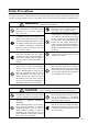
Safety Precautions To ensure correct use of this instrument, read the following points carefully and adhere to them. After you have read this manual, keep it in a safe place where it can be referred to anytime a question arises. (Failure to adhere to the following points may result in death or serious injury.) Do not use the instrument in places Do not disassemble or modify the instrument or the AC adapter. Doing so where flammable or combustible gases may cause a fire or electric shock. (gasoline etc.
Notes on Use • This instrument and the AC adapter supplied as a standard accessory have been designed exclusively for indoor use. • Do not leave the CM-2600d/2500d in direct sunlight or near sources of heat, such as stoves etc. The internal temperature of the instrument may become much higher than the ambient temperature in such cases. • Do not use the CM-2600d/2500d in areas where dust, cigarette smoke or chemical gases are present.
• Do not subject the CM-2600d/2500d to strong impact or vibration. Doing so may cause deterioration in performance or breakdown. • Since the specimen measuring port and integrating sphere are extremely precise optical components, great care should be taken to prevent them getting dirty or exposing them to impact. If you are not going to use the CM-2600d/2500d, put it on the White Calibration Plate (CM-A145). • The CM-2600d/2500d may cause interference if used near a television, radio, etc.
Notes on Cleaning • If the CM-2600d/2500d becomes dirty, wipe it with a soft, clean dry cloth. Never use solvents such as thinner and benzene. • If the White Calibration Plate becomes dirty, wipe it gently with a soft, clean dry cloth. If dirt is difficult to remove, contact the nearest service facility listed on the attached sheet. • If the inner surface of the Target Masks or the inside of the integrating sphere get dirty, contact a KONICA MINOLTA SENSING-authorized service facility.
Contents Safety Precautions .......................................................................................................................... Notes on Use............................................................................................................................... Notes on Storage......................................................................................................................... Notes on Cleaning..................................................................
Contents Setting the Number of Measurements for Auto Averaging........................................................ Setting the Delay Time ............................................................................................................... Zero Calibration ............................................................................................................................. White Calibration.................................................................................................
Contents UV Control ................................................................................................................................. E-118 Target Mode.................................................................................................................................... E-119 Relation Between Measured Data and Target Color .................................................................. E-119 Deleting a Color Difference Target Data.............................................
Contents Conventions This manual describes how to setup the CM-2600d/2500d which the firmware version is 1.40 or higher and use it to take measurements. • Organization The CM-2600d/2500d (Ver. 1.30 or higher) supports two types of the target mode, “linked to each data.” and “defined in COND.”; the procedure and details for these types varies slightly. This manual describes the procedures for the default target mode, which is “linked to each data.”. It only includes information for the “defined in COND.
Chapter 1 Before Using the Instrument E-9
Accessories Standard and optional accessories are available with the instrument. Standard Accessories Make sure that all the following items are present. White Calibration Plate CM-A145 Used to perform white calibration. A data disk containing white calibration data is supplied with this accessory. Memo • This accessory can be used as a table on which to store the CM-2600d/ 2500d. • In the case of the CM-2600d, a Target Mask that is not in use can be stored on this accessory.
Accessories Optional Accessories Zero Calibration Box (CM-A32) Used to perform zero calibration. Hard Case (CM-A148) Can be used for storing the CM-2600d/2500d, the instruction manual and standard accessories, such as the White Calibration Plate and AC adapter. Note The Hard Case is designed purely for storing the above items and must not be used for transportation purposes. Dust Cover Set (CM-A149) Used when measuring powder or wet surfaces.
Names and Functions of Parts 4 3 6 7 2 V MA V SA 1 I O B A 0 5 9 1 Viewfinder Used to check the position of the specimen. By sliding the lever you can check whether the specimen is set correctly. 8 Open 2 Viewfinder lever Used to open/close the viewfinder. By sliding the lever in the direction of the arrow, the white LED will light up and illuminate the specimen, so the specimen can be seen through the viewfinder to check that it is set correctly.
Names and Functions of Parts 6 Measurement area selector Used to change the lens position according to the measurement area. Memo This switch is not available with the CM-2500d. 7 Measuring button (MEAS. button) Press this button to perform calibration or measurement. Memo When setting measurement conditions or tolerances, this button can be used as UNDO button to return to the previous item.
Preparation Attaching/Removing a Target Mask With the CM-2600d, a Target Mask conforming to the selected lens position and measurement condition must be used. A Target Mask that is not in use can be attached to the Target Mask mount section of the White Calibration Plate, so that it can be stored together with the instrument. To attach/remove a Target Mask, follow the procedure given below.
Preparation Storing a Target Mask In the case of the CM-2600d, a Target Mask that is not in use can be attached to the Target Mask mount section of the White Calibration Plate, so that it can be stored together with the instrument. Memo Even in the case of the CM-2500d, when the Target Mask is removed for cleaning the integrating sphere, it can be attached to the Target Mask mount section of the White Calibration Plate to prevent loss and damage.
Preparation Attaching/Removing the “Measuring Base” A “Measuring Base” has been included with the Spectrophotometer CM-2600d/2500d. This allows small specimens to be attached securely to the instrument when they are being measured, and this enables more accurate measurements to be made. The “Measuring Base” is shown in the illustration to the right, and is attached to the base of the CM-2600d/2500d with two screws.
Preparation Cleaning Each Part This section explains how to clean the White Calibration Plate, Target Mask and inside of the integrating sphere. White Calibration Plate Gently wipe off dirt with a soft dry cloth. If dirt is difficult to remove, dampen a cloth with commercially available lens cleaning liquid and wipe. Then remove the liquid with a cloth dampened with water, and leave it to dry. Note Take care not to scratch the White Calibration Plate.
Preparation Inserting the Batteries To supply power to the instrument, the AC adapter (AC-A17) or four AA-size batteries (Alkaline or NiMH battery is recommended for better service life) must be used. Use either the AC adapter or batteries, according to which suits your application. Note • If you are not going to use the instrument for more than two weeks, make sure that the batteries are removed.
Preparation Connecting the AC Adapter Memo Use of the AC adapter (AC-A17) rather than batteries is recommended, since more power will be required when the external output terminal is used to output data to an external device or print it. Note • To supply AC power to the instrument, always use the AC adapter (AC-A17) supplied with the instrument.(Rated: 5 V, 2.8 A) • Before connecting or removing the AC adapter, make sure that power is turned OFF. [Operating Procedure] 1 Make sure that power is OFF (i.
Preparation Turning Power ON Note When turning the power ON for the first time, the display language and measurement mode must be set. For details, refer to page E-27. [Operating Procedure] 1 Set the POWER switch to “|”. The power will be turned ON. Turning Power OFF [Operating Procedure] 1 Set the POWER switch to “ ”. The power will be turned OFF. Auto Power Save Function Power save mode will be activated if the MEAS. button and navigation wheel are not operated for more than three minutes.
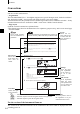
System Configuration Standard accessories Optional accessories AA-size battery ( 4) Personal computer (commercially available) Target Mask 3 mm CM-A147 * Not supplied with the CM-2500d.
Items You Must Know Language Mode Contents on the LCD screen can be displayed in English, Japanese, German, French, Spanish or Italian. In this manual, explanation of operating methods and display is given for English mode. Measurement Mode Two measurement modes (COND and TASK) are available with this instrument, and can be switched from one to another. Measurement Mode COND mode Application Normal measurement mode. Measurement can be performed while the conditions are changed.
Items You Must Know Target Modes • The CM-2600d/2500d supports two Target Modes, “defined in COND.” mode and “linked to each data.” mode, to analyze both measurement data and color difference. As with Language Mode and Measurement Mode, you can select the desired mode when you turn the power ON. • The default setting is “linked to each data.” mode. To switch to “defined in COND.” mode or switch between the target modes, you need to follow the procedure to select target mode.
Items You Must Know Data Saving Data used with this instrument is saved automatically. Although white calibration data is retained in internal memory even after power is turned off, it is still necessary to repeat white calibration each time you switch the power back on.
Chapter 2 Preparation for Measurement E-25
Flow of Measurement For the first time For the second and subsequent times Turning Power On for the First Time (see page E-27) Turning Power ON (see page E-20) Initial Setting (see page E-29) Selecting a Measurement Condition (see page E-33) Setting a Measurement Condition (see page E-34) Zero Calibration (see page E-44) White Calibration (see page E-46) When Checking Color Difference When Not Checking Color Difference Setting a Color Difference Target Data (see page E-48) Selecting a Color Diffe
Turning Power On for the First Time When turning the power ON for the first time, the display language and measurement mode must be set. Setting the Language Mode and Measurement Mode Set the language and measurement mode as follows: [Setting Procedure] 1 While pressing A, turn the power ON. The screen will appear, with the item “LANGUAGE” highlighted. (Back side) TARGET 2 Turn B to select the desired language, then press A.
Turning Power On for the First Time TARGET • If a task(s) has been downloaded to the instrument, both “COND” and “TASK” will be displayed. • Select “COND”. Selecting the Target Mode The default setting is “linked to each data.” mode. The following procedure is required only if you want to switch the target mode. Note • If the Color Data Software “SpectraMagic CM-S9w” is used, switch the target mode to “defined in COND.” mode. • Once the target mode is changed, previous data will be cleared.
Initial Setting The following five initial setting items are available. (1) REMOTE..................... Connects the instrument to the PC to enable bi-directional communications. (2) AUTO PRINT.............. If the instrument is connected to a printer, measured data will be printed automatically each time measurement is taken. (3) CLOCK........................ Adjusts the instrument’s built-in clock. (4) DISPLAY INVERT..... Reverses the display direction. (5) LCD CONTRAST ....... Adjusts the LED’s contrast.
Initial Setting Setting the Date and Time [Setting Procedure]
Initial Setting Setting the Display Direction [Setting Procedure]
Initial Setting Setting the LCD Contrast [Setting Procedure]
Selecting a Measurement Condition Before starting measurement, the desired measurement condition (COND1 to COND6) must be selected. Memo • Up to six sets of measurement conditions (COND1 to COND6) can be set. • Measurement conditions must be set before start of measurement. For details, refer to page E-34. [Setting Procedure] screen 1 Turn B to select one of the conditions (COND1 to COND6), then press A. 2 Turn B to select “FILE”, then press A.
Setting a Measurement Condition Up to six sets of conditions (COND1 to COND6) can be set. Since the instrument will perform measurement according to the selected condition, conditions must be set before start of measurement.
Setting a Measurement Condition Setting the Measurement Area and Specular Component Mode 2 Turn B to select the desired setting, then press A.
Setting a Measurement Condition Setting the UV 3 Turn B to select “UV SETTING”, then press A. For CM-2600d • UV100%: Measurement is performed with an illumination that contains all UV components of Xe flash light source. • UV0%: Measurement is performed with an illumination that contains no UV components of Xe flash light source. • UVADJUSTED: This item can be selected only if UV coefficients have been downloaded from SpectraMagic (Ver.3.2 or higher; excluded Ver.3.5).
Setting a Measurement Condition Selecting Illuminant 2 5 As explained in “Selecting Illuminant 1”, select the desired illuminant, then press A. • Same as those given in “Selecting Illuminant 1” • To display MI (metamerism index), an illuminant must be selected for ILLUMINANT 2. Selecting the Observer 6 Turn B to select the desired observer angle, then press A.
Setting a Measurement Condition Selecting the Display Mode 7 Turn B to select the desired display mode, then press A. • DIFF&ABS: Displays the absolute value and the color difference in relation to the target color. (Only absolute value or only color difference can be displayed.) If pass/fail judgment is made according to the specified box color difference tolerances, the failed factor of the measured data will be highlighted.
Setting a Measurement Condition Selecting a Color Space 8 Turn B to select the desired color space, then press A. Locating the highlighted cursor to by turning B will display the next page of the color space list. Locating the highlighted cursor to by turning B will display the previous page of the color space list.
Setting a Measurement Condition • The coefficient for CIE00 (kl:kc:kh) is (1:1:1). This can be changed using SpectraMagic NX (except for Ver. 1.50 or earlier). If the coefficient (kl:kc:kh) is re-specified after measurement, the measurement data will be replaced with data calculated based on the new coefficient.
Setting a Measurement Condition Setting the Number of Measurements for Manual Averaging Manual averaging settings can be made as follows: For details, refer to “Manual Averaging” (page E-76). 9 Turn B to select the number of measurements to be performed, then press A. • TIMES: Specify the number of measurements to be performed (2 to 30). If “- -” is selected, manual averaging will not be performed. • Keeping B held down to left or right will cause the value to change continuously.
Setting a Measurement Condition Setting the Delay Time 12 Turn B to set the desired delay time, then press A. • DELAY TIME: The delay time is used to prevent influences caused by movement of the hands, and is the duration from when the MEAS. button is pressed until the lamp flashes and measurement is performed. Specify the desired delay time (0.1 to 3.0 seconds in steps of 0.1 seconds). If “0.0” (second) is specified, no delay time will be provided.
Setting a Measurement Condition • “T*” does not appear if “defined in COND.” mode is selected. Memo Selecting “CALIBRATION” by turning B and pressing A will display the screen. So, perform the desired calibration according to step 3 and subsequent steps given in “Zero Calibration” (from page E-44) or “White Calibration” (from page E-46). Note Depending on the target mode selected, some of the options displayed will be different.
• “T*” does not appear if “defined in COND.” mode is selected. Selecting “PREV” by turning B and pressing A again will cause the screen to reappear. So, set another measurement condition according to the procedure given in “Selecting a Measurement Condition” and “Setting a Measurement Condition” (from page E-34).
Zero Calibration Zero Calibration When you use this instrument for the first time or when you have initialized it, zero calibration must be performed. Zero calibration is also sometimes required when measurement conditions are changed. Once zero calibration is completed, the zero calibration data will be kept even if the power is turned OFF. Thus, it is not necessary to perform zero calibration each time the power is turned ON. Memo • The effects of stray light inside the measuring part (i.e.
3 Turn B to select “ZERO”. 4 Direct the specimen measuring port into the air. 1m or more • Never place the specimen measuring port toward a light source. • Keep the specimen measuring port more than 1m away from any reflective items (hands, desks, walls etc.). 5 Make sure that is displayed, then press C (MEAS. button). Zero calibration will be performed. When zero calibration is complete, the screen will reappear.
White Calibration White Calibration White calibration must be performed prior to start of measurement after the power is turned ON. Memo • Own calibration data has been registered to the White Calibration Plate supplied with the instrument. • Although white calibration data is retained in internal memory even after power is turned off, it is still necessary to repeat white calibration each time you switch the power back on.
3 Turn B to select “WHITE”. 4 Place the instrument on the correct White Calibration Plate (i.e. the calibration plate whose plate No. is displayed in the screen). 5 Make sure that Note that the White Calibration Plate No. is displayed. is displayed, then press C (MEAS. button). White calibration will be performed. When white calibration is complete, the measurement screen will reappear.
Setting a Color Difference Target Data Setting a Color Difference Target Data To measure the color difference between two specimens, the color of one of the specimens must be set as the target color. Up to 1700 target colors can be set for color difference measurement. (700 can be set in the “defined in COND” mode.) To set a target color, follow the procedure given below.
4 Place the specimen measuring port to the specimen. 5 Make sure that is displayed, then press C (MEAS. button). The lamp will flash, measurement will be taken, then the result will appear on the LCD. Memo • The navigation wheel and MEAS. button cannot be used for three seconds after the MEAS. button is pressed, if “UV100%” has been set for “UV SETTING”, or for four seconds if “UV0%” or “ADJUSTED” has been set.
Selecting a Color Difference Target Data Selecting a Color Difference Target Data To measure the color difference between two specimens, the target color to be used for measurement must be selected from those set in “Setting a Color Difference Target Data”. To select a target color, follow the procedure given below. [Setting Procedure] screen 1 Turn B to select “TARGET”, then press A. • “T*” is the number of the color difference target data for the next measurement.
Note To make pass/fail judgment during measurement, it is necessary to set tolerances for the target color to be used. For details, refer to “Setting Color Difference Tolerances” (page E-52). Deleting a Color Difference Target Data There are two methods for deleting target color data. One is to delete the target color data set in “T*” of the measurement conditions (COND 1 to COND 6) one by one. The other is to delete all the target color data set in the instrument.
Setting Color Difference Tolerances Setting Color Difference Tolerances This instrument allows you to set tolerances for the measured color difference, to make pass/fail judgment. Pass/fail judgment is made based on two types of tolerances: box tolerances and elliptical tolerances. Prior to start of measurement, tolerances must be set. Memo • Two types of tolerances are available (box tolerances and elliptical tolerances).
Setting Color Difference Tolerances 3 Turn B to select the desired target color no. (T*), then press A. “E” will return to “D”. • Keeping B held down to left or right will cause the target color No. to change continuously. 4 Turn B to select “TOLERANCE”, then press A. A screen that allows selection of the tolerance type will appear. If tolerances have already been set, they will be displayed, so skip to step 6. • Example when “M/I+E” is set for “MASK/GLOSS” condition item.
Setting Color Difference Tolerances 7 Turn B to select the value for an item to be set, then press A. The selected value will be set, and the cursor will move to the next value. Memo Keeping A held down will cause the cursor to move from one value to another continuously. The cursor will stop when it reaches “ADJUST”. • + (“+” tolerance range) : “----” (No setting), 0.1 to 20.0 • : (“-” tolerance range) : “----” (No setting), 0.1 to 20.
Setting Color Difference Tolerances Elliptical Tolerance Provided to judge whether the measured color difference is within the ellipse set for the target color. Memo • Elliptical tolerances must be set using the “L*a*b*” color space axis if “L*C*h” has been selected as the color space. • After elliptical tolerances have been set, if the color space is switched to another (e.g.
Setting Color Difference Tolerances 4 Turn B to select “TOLERANCE”, then press A. A screen that allows selection of the tolerance type will appear. If tolerances have already been set, they will be displayed, so skip to step 6. 5 Turn B to select “ELLIPTICAL”, then press A. 6 Turn B to select “ADJUST”, then press A. 7 Select the value for an item to be set, starting from the top, then press A. The selected value will be set, and the cursor will move to the next value.
Setting Color Difference Tolerances • Keeping B held down to left or right will cause the value to change continuously. • “MAJOR” in the L*a*b* color space will be “a*” axis when “OFFS.” and “ROTAT.” on the “a*b*” plane are “0” (ZERO). • To change a value that has been set, press C (MEAS. button) in the screen where “↑ : ” is displayed. This will take you to the previous items, so change the value. MINOR MAJOR OFFS. ROTAT.
Setting Color Difference Tolerances Clearing Tolerances To change the tolerance type, it is necessary to clear the currently set tolerances. To clear the currently set tolerances, follow the procedure given below: [Setting Procedure] screen 1. Turn B to select “TOLERANCE”, then press A. The currently set tolerances will be displayed. 2. Turn B to select “RESET”, then press A. A message confirming you whether to clear the tolerances will appear. 3.
Setting Color Difference Tolerances E-60
Chapter 3 Measurement E-61
Measurement To perform measurement, you need to switch from a screen in which “BREAK” is displayed to the measurement screen. To perform measurement, follow the procedure given below: Note • Prior to start of measurement, be sure to perform white calibration. For details, refer to “White Calibration” (page E-46). • To measure color difference, it is necessary to set target colors first and then select the one to be used for measurement.
Measurement Memo • Measurement will no longer be possible once the total number of target color data and measured data reaches 1700 (700 in the “defined in COND.” mode). In this case, delete some target color data or measured data. • The navigation wheel and MEAS. button cannot be used for three seconds after the MEAS. button is pressed, if “UV100%” has been set for “UV SETTING”, or for four seconds if “UV0%” or “ADJUSTED” has been set.
Displaying the Measurement Results At the end of measurement, the measurement results will be displayed on the LCD according to the specified measurement condition. Typical measurement result screens are shown hereafter. To change LCD’s display contents, change them in the corresponding screen. For details, refer to “Setting a Measurement Condition” (from page E-34). Measured Data The following screen appears if “DIFF&ABS” has been selected for “DISPLAY” mode.
Displaying the Measurement Results Pass/Fail Judgment The following screen appears if “PASS/FAIL” has been selected for “DISPLAY” mode and tolerances have been set. • When the result is “PASS” 1 2 3 4 5 6 7 8 9 0 A B C D E F Ready to measure. Currently selected no. Mask/gloss/UV at the time of measurement Currently selected observer/illuminant Currently selected measured data no. Currently selected target color data no. PASS/FAIL judgment result. Measurement date.
Displaying the Measurement Results Color Difference Graph The following screen appears if “COLOR GRAPH” has been selected for “DISPLAY” mode. The L*a*b* color difference value and the assessment message will be displayed in this screen regardless of the color space selected for “COLOR SPACE” condition item. The data will be plotted in a color difference graph with the selected target color as the origin. (If “*/I+E” has been selected as specular component mode, only the graph will be displayed.
Displaying the Measurement Results • Color difference graph H I J K L M N L* axis (color difference graph) a* axis (color difference graph) b* axis (color difference graph) Measuring point Scale for each axis Specified box tolerances Position of target color Spectral Reflectance Graph The following screen appears if “SPECT. GRAPH” has been selected for “DISPLAY” mode. Ready to measure. Currently selected no.
Displaying the Measurement Results B C D E F Deletes the currently displayed measured data. Displays other measred data. Outputs the currently displayed measured data to the printer. Returns to the screen. Appears if there is insufficient battery power when the instrument is powered by the battery. If appears, replace the batteries with new ones. Assessments The following screen appears if “ASSESSMENTS” has been selected for “DISPLAY” mode and tolerances have been set.
Displaying the Measurement Results • Displaying Assessment by Elliptical Tolerance 1 2 3 4 5 6 7 8 9 0 A B C D E F Ready to measure. Currently selected no. Mask/gloss/UV at the time of measurement Currently selected observer/illuminant Currently selected measured data no. Currently selected target color data no. Color Difference from the target, result of PASS/FAIL judgment and message indicating the deviation direction Measurement date. For the year, only the lower two digits are displayed.
Displaying the Measurement Results Switching the Display Contents of the Measurement Results In the measurement screen that appears at the end of measurement, the following data will be displayed according to the settings made in the screen. The display contents can also be changed. Memo Selecting “DISP” by turning B in a measurement screen in which “DISP” is displayed and then pressing A will allow you to switch the display contents of the measurement results.
Displaying the Measurement Results Screen Switching Measurement Screen 1 Measurement Screen 2 Measurement Screen 3 Color difference only Absolute value only Metamerism index (MI)* Color difference only Absolute value only Metamerism index (MI)* Color difference, absolute value Color difference, absolute value Color difference only Color difference, absolute value Color difference, absolute value Absolute value only Color difference, absolute value Absolute value only PASS or FAIL Metamerism
Displaying the Measurement Results Deleting Measured Data There are two methods of deleting measured data. One is to delete the data items displayed on the LCD one by one. The other is to delete all the data items for the selected measurement condition (COND1 to COND6). Deleting Data One by One Data currently displayed on the LCD can be deleted. This can be done in the measurement screen. 1. Turn B to select “D”, and then press A. “D” will change to “E”. 2.
Displaying the Measurement Results Deleting All Data At Once All the data items for the selected measurement condition (COND1 to COND6) can be deleted at once. Note • Never turn OFF the instrument while global deletion is in progress. • Should the instrument be turned OFF during global deletion, the measured data for all the measurement conditions (COND1 to COND6) as well as for all the tasks will be deleted. However, measurement conditions (e.g. color space) and target color data will be retained.
Displaying the Measurement Results Abbreviations on LCD Display To facilitate the user’s understanding of various types of information displayed on the instrument’s LCD, the following abbreviations are commonly used. • For notation of values to be set in each setting screen (e.g. measurement conditions), refer to the description given in the corresponding operating procedure.
Displaying the Measurement Results Measurement Results for “linked to each data.” This instrument can set multiple target color data numbers and select one of those for displaying the results for the color difference. It can also easily switch the selected target color number using the navigation wheel. The “defined in COND.” target mode can use these functions to calculate multiple color differences for measurement data, and make pass/fail judgments based on this.
Displaying the Measurement Results When the Target Color Data No. has Been Deleted If the target color data for a number is deleted, the target color for data to which that number was associated is set to that of the next highest number. The target color number is reset to that of the number for which there is a target color data number. With “linked to each data.” target-mode, the measured data is saved with target color number that was specified for it at the time of measurement.
Chapter 4 Other Functions E-77
Measuring the Average When taking measurements or setting target colors, more accurate data can be obtained if the averaging function is used. The following two averaging functions are available. • Manual Averaging: When the color of the specimen is not uniform, measurements are performed at different positions on the specimen and then the average of the measured reflectance data is calculated. This gives the average data of the entire specimen.
Measuring the Average 2 Place the specimen measuring port to the specimen to be measured, and then press C (MEAS. button). If 2 is set for “MANUAL AVG. TIMES” or if 3 or a higher value is set and the standard deviation is not below the specified one, place the specimen measuring port to the next place and then press C (MEAS. button). • The number of completed measurements including the one currently in progress and standard deviation will be displayed during measurement.
Measuring the Average Auto Averaging Measurement is repeated the specified number of times in the same position on the specimen and then the average of the measured reflectance data is calculated. This will improve the accuracy of the measured data. Set the number of measurements to be performed and the standard deviation, and then start measurement. Note Before starting auto averaging, make sure that the number of measurements to be performed is set.
Pass/Fail Judgment for Color Difference This instrument allows you to set tolerances for the measured color difference, to make pass/fail judgment. Two kinds of pass/fail judgment methods are available. One is based on the specified box tolerances, and the other is based on the specified elliptical tolerances. In “linked to each data.” mode, the number of the target color data selected at the time of measurement or the measured data are passed/failed based on the tolerances.
Pass/Fail Judgment for Color Difference 4 Turn B to select “TOLERANCE”, then press A. 5 If they are satisfactory, turn B to select “BREAK”, then press A. 6 Place the specimen measuring port to the specimen, and then press C (MEAS. button). The currently set tolerances will be displayed. The measurement screen will appear. Values for the items that have failed will be highlighted.
Pass/Fail Judgment for Color Difference Memo • If “PASS/FAIL” has been selected as the display mode, “PASS” will be displayed only when all the items have passed. • If “DIFF/ABS” has been selected as the display mode, the values for the items which have failed will be highlighted • If a color difference has not been set, when the target mode is “linked to each data.”, and the target color data number set at the time of measurement is deleted, “----” appears instead of “PASS/FAIL”.
Pass/Fail Judgment for Color Difference 4 Turn B to select “TOLERANCE”, then press A. 5 If they are satisfactory, turn B to select “BREAK”, then press A. 6 Place the specimen measuring port to the specimen, and then press C (MEAS. button). The currently set tolerances will be displayed. The measurement screen will appear.
Assessments This instrument allows assessment of measurement results by simultaneously displaying the direction of tint deviation from the target color, the color difference from the target color and pass/fail judgment based on the specified tolerances. Note To use this function, make sure that color difference tolerances are set in advance. Assessment by Box Tolerances [Setting Procedure] screen 1 Turn B to select “TARGET”, then press A. 2 Turn B to select “D”, then press A.
Assessments 5 If they are satisfactory, turn B to select “BREAK”, then press A. 6 Place the specimen measuring port to the specimen, and then press C (MEAS. button). The measurement screen will appear. The color difference from the target color, pass/fail judgment result based on the specified box tolerances and direction of tint and brightness deviation will be displayed. • The color space to be used as the assessment axis differs depending on the selected color space.
Assessments • The following deviation directions can be indicated by a message. L*: LIGHTER/DARKER a*: +RED (stronger red)/-RED (weaker red) / +GREEN (stronger green)/-GREEN (weaker green) b*: +YELLOW (stronger yellow)/-YELLOW (weaker yellow) / +BLUE (stronger blue)/-BLUE (weaker blue) C*: DULLER/VIVID H*: +RED (stronger red)/+YELLOW (stronger yellow) / +GREEN (stronger green)/+BLUE (stronger blue) For E*, only the pass/fail judgment result will be displayed by “PASS” or “FAIL”.
Assessments 4 Turn B to select “TOLERANCE”, then press A. 5 If they are satisfactory, turn B to select “BREAK”, then press A. 6 Place the specimen measuring port to the specimen, and then press C (MEAS. button). The currently set tolerances will be displayed. The measurement screen will appear. The color difference, direction and amount of tint and brightness deviation from the target color will be displayed.
Assessments Type Specular component Displayed value Pass/fail judgment Color difference PASS E* I+E Color difference PASS E* Box FAIL tolerance Color difference SCI or SCE E* E* Measured value, with “PASS” to the right Highlighted measured value, with highlighted message to the right Measured value, with “PASS” to the right FAIL Highlighted measured value, with highlighted “FAIL” to the right PASS Measured value, with “PASS” to the right.
Connecting to an External Device Connecting a PC or printer to the external output terminal on the instrument allows the transfer of data between the instrument and PC or printing of the measurement results. Connecting a Personal Computer Connecting a PC (PC-AT compatible) to the instrument with a RS-232C cable will allow uploading the data stored in the instrument’s memory to the PC or downloading data from the PC to the instrument.
Connecting to an External Device RS-232C Pin Assignment and Cable Wiring Diagram Instrument Personal Computer (For D-sub, 9-pin) 5 1 Pin No. 2 3 5 7 8 8 Signal RXD TXD GND RTS CTS 4 9 Signal RXD TXD GND RTS CTS 3 8 2 7 1 6 Pin No. 2 3 5 7 8 Switching to Remote Mode To transfer data between the instrument and the PC, the instrument must be switched to remote mode. To switch to remote mode, follow the procedure given below. [Setting Procedure] Make sure that power to the instrument is turned OFF.
Connecting to an External Device 3. Turn B to select “MENU”, then press A. The
Connecting to an External Device Outputting to a Printer Connecting the instrument to a printer with a printer cable allows printing the measured data or the color difference target data stored in the instrument’s memory. Two printing methods are available. One is to print automatically each time measurement is taken (this is called “Auto Print”; measured data only), and the other is to print the currently displayed measured data, pass/fail results and color difference target data. Memo If “SPECT.
Connecting to an External Device Printer Cable Wiring Diagram • For D-sub, 9pin Instrument Printer (For D-sub, 9-pin) 5 1 Pin No. 3 5 8 8 Signal TXD GND CTS 4 9 3 8 Signal DATA GND BUSY 2 7 1 6 Pin No. 3 5 8 • For D-sub, 25pin Instrument 1 Pin No. 3 5 8 Printer (For D-sub, 25-pin) 8 Signal TXD GND CTS Signal DATA BUSY GND Pin No. 2 5 7 Auto Print If Auto Print has been setup beforehand, the measurement data can be printed as each measurement is made.
Connecting to an External Device 2. Turn the power ON. 3. Turn B to select “MENU”, then press A. 4. Turn B to select “AUTO PRINT”, then press A. 5. Turn B to select “ON”, then press A. Measured data will be printed automatically each time measurement is taken. Printing Measured Data Memo To print measured data, make sure that the instrument is connected to the printer with a printer cable.
Connecting to an External Device [Procedure] This operation must be started from a screen in which measured data is displayed. 1. Turn B to select “D”, then press A. “D” will change to “E”. 2. Turn B to select the measured data to be printed, then press A. “E” will return to “D”. • Keeping B held down to left or right will cause the measured data No. (No.*) to change continuously. 3. Turn B to select “ ”, then press A.
Connecting to an External Device • Print Example 2 Display mode: “SPECT.
Connecting to an External Device Printing Color Difference Target Memo To print color difference target data, make sure that the instrument is connected to the printer with a printer cable. Note • The instrument and printer must be connected using a printer cable that is wired as shown in “Printer Cable Wiring Diagram” (page E-92). • Before connecting, make sure that the power to both the instrument and printer is turned OFF. [Procedure] This operation must be started from the screen. 1.
TASK Mode What is TASK Mode? TASK mode is the function that allows you to perform measurement according to the messages displayed in the LCD indicating the measurement procedure. The messages can be created by using the previously used software SpectraMagic (Ver. 3.2 or higher; except for Ver. 3.5) with your PC and downloading it as a TASK. Up to ten steps can be set for each task, and up to six tasks can be downloaded to the instrument.
TASK Mode 3 Turn B to select “MENU”, then press A. 4 Turn B to select “REMOTE”, then press A. 5 Download a task using SpectraMagic (Ver.3.2 or higher; excluded Ver.3.5). The
TASK Mode [Setting Procedure] Make sure that power to the instrument is turned OFF. 1 While pressing A, turn the power ON. (Back side) The screen will appear, with the item “LANGUAGE” highlighted. 2 Turn B to select the desired language, then press A. • When the cursor moves to the desired language, all the text will be displayed in the selected language. 3 Turn B to select “TASK”, then press A. 4 Turn B to select the desired target mode, then press A.
TASK Mode The screen will appear. • Example when tasks 1, 2 and 5 have been downloaded. 5 Turn B to select “TASK*”, then press A. A message asking you to check the currently set mask and measurement area will appear. 6 Check the Target Mask and measurement area selector switch, then press A. The screen will appear. Note that the White Calibration Plate No. is displayed. 7 Turn B to select “ZERO”, then press C (MEAS. button).
TASK Mode Turn B to select “WHITE”, and then press C (MEAS. button). Note Place the instrument on the correct White Calibration Plate (i.e. the calibration plate whose plate No. is displayed in the screen). Memo • If the white calibration data has already been set, the procedure will move to step 8 automatically. • If does not appear due to the auto power save function, this may be due the fact that it can take time to start calibration after C is pressed.
TASK Mode the specimen measuring port to the specimen according to the message dis10 Place played, make sure that is displayed, then press C (MEAS. button). Memo If does not appear due to the auto power save function, this may be due the fact that it can take time to start measurement after C is pressed. 11 Turn B to select “NEXT” then press A. The message for “JOB*” displayed for the previous measurement will appear.
TASK Mode Turn B to select “END”, then press A. Measurement will be quit. Memo If you made a setting to save the average at step 8, the average of all measurement in a series will be calculated and displayed at the end of the task’s last “JOB*”. In this case, only the calculated average will be stored in the instrument’s memory. The measurement result for each “JOB*” will not be saved.
TASK Mode E-106
Chapter 5 Troubleshooting E-107
Error Messages The following messages may appear while you are using the instrument. If such messages appear, take the necessary actions shown in the table below. If the trouble does not go away in spite of taking action, contact a KONICA MINOLTA SENSING-authorized service facility. Memo Messages that may be displayed on the LCD are given in the table below. For communication error check codes, refer to the separate document.
Error Messages MessageCorrective Action ER13 ERROR IN A/D Symptom/Possible Cause Failed during A/D conversion. • Faulty A/D converter • Break down of circuits relating to the A/D converter Corrective Action Turn the power OFF, and then turn it ON again. If this message keeps appearing, contact a KONICA MINOLTA SENSING -authorized service facility. ER17 Clock IC is not working correct- Contact a KONICA MINOLTA SENSING-authorized service faINCORRECT CLOCK OPERA- ly.
Troubleshooting If an abnormality has occurred with the instrument, take necessary actions as given in the table below. If the instrument still does not work properly, turn the power OFF, and then turn it ON again. If the symptom remains, contact a KONICA MINOLTA SENSING-authorized service facility. Symptom LCD is blank.
Troubleshooting Symptom Measurement data or settings are not held in memory, and disappear immediately. Check Point The instrument’s backup batteries may be low immediately after purchase or following a period of prolonged use. Turn the power of the instrument ON to charge the backup batteries. Under this condition, the batteries can be fully charged in 25 hours. Action The backup batteries have an expected service life of approximately ten years.
Troubleshooting E-112
Chapter 6 Appendix E-113
Principles of Measurement Illuminating/Viewing System The flow of measurement is shown below. This instrument utilizes the D/8 geometry conforming to CIE No.15, ISO 7724/1, ASTM E1164, DIN 5033 Tei17, and JIS Z8722-1982 (diffused illumination/8º viewing system) standards, and offers simultaneous SCI (specular component included) and SCE (specular component excluded) measurements. 1 Illumination Light from xenon lamps diffuses in the integrating sphere and illuminates the specimen uniformly.
Principles of Measurement Illumination Area and Measurement Area The CM-2600d allows selection of either SAV (ø3 mm) or MAV (ø8 mm) measurement area according to the specimen and applications. A Target Mask (illumination area) suitable for the selected measurement area must be installed. Note With the CM-2500d, only MAV (ø8 mm) is available. Target Mask Since this instrument does not have automatic Target Mask matched to the selected measurement area must be attached correctly.
Principles of Measurement Simultaneous SCI/SCE Measurement The CM-2600d/2500d employs simultaneous SCI/SCE measurement method. With the conventional models, SCI (Specular Component Included) and SCE (Specular Component Excluded) need to be switched mechanically by opening/closing the optical trap provided inside the integrating sphere.
Target Mode Relation Between Measured Data and Target Color • In “linked to each data.” mode, there is specific target color data associated with the selected number of the target color data at the time of measurement. • In “defined in COND.” mode, the target color data depends on the conditions.
Specifications Specifications Model Illuminating/viewing system CM-2600d CM-2500d d/8 (diffused illumination, 8-degree viewing angle), equipped with simultaneous measurement (not switched mechanically) of SCI (specular component included)/SCE (specular component excluded). (Conforms to CIE No.15, ISO 7724/1, ASTM E1164, DIN 5033 Tei17, JIS Z8722 Condition c, standard.
Specifications Model CM-2600d CM-2500d Display Spectral value/graph, colorimetric value, color difference value/ graph, PASS/FAIL result, Assessment (except in Japanese mode), relative gloss value Color space/colorimetric data L*a*b*, L*C*h, CMC (1:1), CMC (2:1), CIE94, Hunter Lab, Yxy, Munsell, XYZ, MI, WI (ASTM E313), YI (ASTM E313/ASTM D1925), ISO Brightness (ISO 2470), Density status A/T, WI/Tint (CIE/Ganz), CIE00 Storable data sets 1700 pieces of data (as SCI/SCE 1 data) * 700 pieces of data i
Dimensions Dimensions (mm) The measurement area selector is not available with the CM-2500d.
Dimensions E-121
Menu Structure Menu Structure The navigation wheel of the CM-2600d/2500d can be used to select menus and items in the LCD to set the measurement conditions and measurement results display. The following figure is the Menu Structure diagram of the CM-2600d/2500d. This is a tree diagram for the menus or the items that can be selected in the display of the instrument. Reading the menu structure diagram • is the display title in the diagram.
“TASK” Mode “COND” mode * (page E-29) * REMOTE AUTO PRINT CLOCK DISPLAY INVERT LCD CONTRAST
E Es 9222-1856-40 © 2002-2005 KONICA MINOLTA SENSING, INC.