E INSTRUCTION MANUAL 9224-2885-11 H-A909
Thank you for purchasing the Minolta Dimâge Scan Elite. The Dimâge Scan Elite F-2900 is a dual format film scanner capable of scanning 35mm and with the optional AD-10 APS Adapter, Advanced Photo System film. This manual has been designed to help you understand the operation of your scanner. Please read this manual thoroughly to realise all the benefits of your scanner.
FOR PROPER AND SAFE USE Please read and understand each caution before using this product. WARNING To avoid fire or electric shock: • Use only within the voltage range specified on the back of unit. • Do not expose this unit to liquids. • Do not insert metal objects into this unit. • Do not touch the cord or plug if your hands are wet. • Unplug this unit when it is not in use. Improper use of the power cord may result in fire or electric shock. • Insert the plug securely into an electrical outlet.
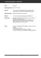
SYSTEM REQUIREMENTS – PC AT CPU: IBM PC/AT compatible with An Intel Pentium or later processor or better. An Intel Pentium or later when Windows NT 4.0 is installed. • Support cannot be provided for custom or home built machines. Operating System: Windows 95 (incl. OSR2), Windows 98, or Windows NT 4.0. Memory: A minimum of 32 MB RAM. Hard Disk Space: 90 MB of available hard disk space.
SYSTEM REQUIREMENTS – MACINTOSH CPU: Power PC Operating System: Mac OS 7.5 to 8.6 Memory: A minimum of 8 MB application RAM in addition to the requirements for the Mac OS and Adobe Photoshop™ Hard Disk Space: 90 MB of available hard disk space. Monitor: 13 inch monitor capable of displaying 32,000 colors.
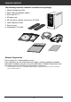
PACKAGE CONTENTS The following contents should be included in this package. 1. Minolta Dimâge Scan Elite 2. 35mm Slide and Negative holders 3. SCSI cable SC-11 4. AC power cord 5. DS_Elite driver software and manuals CD ROM 6. Quick Reference Guide 7. Warranty card 8. Photoshop LE CD ROM Software Registration Please register this software before using it… Once registered, you will receive technical support, software upgrade and product information.
TABLE OF CONTENTS FOR PROPER AND SAFE USE . . . . . . . . . . . . . . . . . . . . . . . . . . . . . . . . . . . . . . . . . . . . .1 SYSTEM REQUIREMENTS PC/AT . . . . . . . . . . . . . . . . . . . . . . . . . . . . . . . . . . . . . . . . . . .2 SYSTEM REQUIREMENTS Macintosh . . . . . . . . . . . . . . . . . . . . . . . . . . . . . . . . . . . . . . . .3 PACKAGE CONTENTS . . . . . . . . . . . . . . . . . . . . . . . . . . . . . . . . . . . . . . . . . . . . . . . . . . . .4 TABLE OF CONTENTS . . . . . . . .
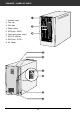
SCANNER – NAMES OF PARTS 1. Indicator lamp 2. Film slot 3. Film door 4. Power switch 5. SCSI port - DB25 6. Terminator power switch 7. SCSI ID switches 8. SCSI port - SCSI-1 9.
SCANNER SETUP
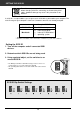
SETTING THE SCSI ID Turn off the computer and all the devices in the SCSI chain before changing SCSI IDs, connecting, or disconnecting SCSI cables. Hardware damage may occur if this precaution is not followed. A SCSI ID is a unique address you assign to each SCSI device connected to your computer. The SCSI ID range of your computer is from 0 to 7, however some ID's are already occupied.
CONNECTING THE HARDWARE Connecting the SCSI Cable This scanner has been packaged with the SCSI cable SC-11 (DB25-to-SCSI-1). See your dealer if you require a different SCSI cable. • To meet FCC regulations, the SCSI cables used with this scanner must be equipped with ferrite cores. BEFORE YOU BEGIN… TURN THE COMPUTER AND ALL CONNECTED DEVICES OFF. 1. Place the scanner on a level surface. 2.
CONNECTING THE HARDWARE If there are other devices in your SCSI chain… 4. Plug the SCSI cable from the next device into the open port on the back of the scanner. 5. Plug the power cord into the scanner’s AC socket, then plug it into a grounded outlet. This decive is to be used with a po wer source within the voltage as sp ecified on the back of un it.
CONNECTING THE HARDWARE If the Dimâge Scan Elite is the last or only device in your SCSI chain… 4. Turn the terminator power switch (switch 4) to ON. • An external terminator is not necessary with this scanner. Terminating th e SCSI chain helps to supp ress electron ic noise in the S CSI chain. Not terminatin g the SCSI ch ain can cause slow downs, data errors, crashe s, and other unpredictable errors. 5. Plug the power cord into the scanner’s AC socket, then plug it into a grounded outlet.
INSTALLING THE SOFTWARE – PC/AT WINDOWS 95/ WINDOWS 98 WINDOWS NT Dimâge Scan Elite for Windows Setup installs the Twain and Twain_32 driver software into the drive and folder you select. • The appearance and/or wording of some dialog boxes may vary depending on the version of Windows running on your machine. • These installation instructions assume drive D is the CD-ROM drive. 1. Turn on the scanner, then turn on the PC. 2. Start the Windows operating system.
INSTALLING THE SOFTWARE – PC/AT 5. Select Run form the Start menu. The Run dialog box will appear. 6. Select D:\DRIVER\ENGLISH\Setup.exe from the Open drop-down list, then click on OK. • If your CD-ROM drive is not the D drive, replace the D with the appropriate designation for your CD-ROM drive. The installer flash will appear. 7. Click on Next. The Software License Agreement will appear. 8. After reading the agreement, click on Yes.
INSTALLING THE SOFTWARE – PC/AT The Setup Type dialog box will appear. 10. Choose either Typical or TWAIN Files install, then click on Next. The Select Program Folder dialog box will appear. 11. Click on Next. • Setup will begin. The Setup Successful dialog box will appear. 12. Click on Close. The following dialog box will appear. 13. Click on Yes.
INSTALLING THE SOFTWARE – MACINTOSH Please remove or disable any antivirus system extensions before launching this installer. These extensions may conflict with the operation of this installer. Replace or re-enable them when installation is complete. Hold the shift key down during startup to disable the extensions. 1. Turn on the Dimâge Scan Elite, then turn on your Macintosh. 2. Quit any open applications. 3. Insert the Dimâge Scan Elite CD-ROM into the CD-ROM drive. • will appear on the desktop. 4.
INSTALLING THE SOFTWARE – MACINTOSH The following dialog box will appear. Install type pulldown menu Install location pulldown menu Name and icon of the selected install drive or folder. • If you have Power Book G3, select the DS Elite for PBG3 from the Install type pulldown menu. 9. Select the install drive (or folder) and type from the pulldown menus. • You can also click on to select an install drive. 10. Click on . The following message appears when the installer is finished. 11. Click on .
S TA N D A R D O P E R AT I O N SCAN FLOW Launch the Software Set the Preferences Load the Film Holder Insert the Film Holder Specify the Film Type Prescan Orient the Image Correct the Brightness, Contrast, and Color Specify the Job Type Scan Save
LAUNCHING THE SOFTWARE The TWAIN driver lets you control the software through another application, such as your image editing software. Launching the TWAIN Driver — Windows This manual uses Adobe Photoshop 4.0.1 as the host application. Commands may vary among applications. 1. Open the host application. 2. Select File > Import > Select TWAIN_32 Source... The Select Source dialog box appears. 3. Select DS_Elite, then click on Select. 4. Select File > Import > TWAIN_32.
LAUNCHING THE SOFTWARE The plug-in software lets you access the software through Adobe Photoshop. Launching the Plug-in — Macintosh 1. Launch Adobe Photoshop. 2. Photoshop 4.0.1 and newer: Select File > Import > DS_Elite Plug-in. Photoshop 3.0.5: Select File > Acquire > DS_Elite Plug-in The software is ready for use when the Main window appears (p.20). Use the utilty software, as a stand alone application, when you just want to scan the photographic image and store.
MAIN WINDOW—NAME OF PARTS MAIN window Command Window part (see below) Index scan (see page 56) / Prescan (see page 26) / Image Correction (see page 34) tab part Scan Setting part (see page 68) The Command Window part — Name of parts Film format list box Close button Film format list box Status bar Index Scan button Help button ( Prescan button Preferences button Scan button APS Rewind button Navigation button 20 on Macintosh)
SETTING THE PREFERENCES 1. Click on . The Preference Dialog Box — Name of parts COLOR MATCHING Settings (See page 66.) APS Settings (See page 57.) 2. Set the preferences as desired. Auto Expose for Slides checkbox Select this checkbox when scanning underexposed slides. Close Driver software After Scanning checkbox Closes the scanner's driver software after the scan is complete. Color depth Setting box The pixel depth of each color channel used to scan your image (RGB or CMY).
LOADING THE FILM HOLDER Using the included 35mm negative and slide holders, the Minolta Dimâge Scan Elite can scan mounted or unmounted… • 35mm colour negatives • 35mm black & white negatives • 35mm colour slides • 35mm black & white positives Advanced Photo System negatives and slides can also be scanned using the optional AD-10 APS Adapter. See page 57. Loading the Negative Holder 1. Open the film holder. 2. Place the film in the film holder emulsion side up.
LOADING THE FILM HOLDER Loading the Slide Holder 1. Insert slides into the slide holder emulsion side up. • Brush dust off the the slide before placing it into the film holder. • Slide mounts must be thicker than 1 mm and thinner than 2 mm to fit into the slide holder. • Orient the slides horizontally, not vertically. Do not scan gl ass mounted slides . Glass mounts bend the light from the line scanner, producing ba d results.
INSERTING THE FILM HOLDER INTO THE SCANNER The notches in the film and slide holders identify the position of the scanning windows. Push the holder all the way in to scan the last frame on that side of the film holder. Remove, flip, then re-insert the film holder to scan the frames on the other side of the holder. Insert the negative holder into the scanner’s film slot to scan frames 1, 2, or 3. • Frames 1 or 2 with the slide holder. The white should be up rig mark ht.
PREVIEW—SETTING FILM TYPE Setting the Film Type 1. Select 35mm from the film format drop-down list. • The Preview window appears. 2. Select the film type from the film type drop-down list. 3. Click on in the Main window. The previewed image will appear in the Preview window. Press Ctrl whe n previewing ( on the Macintosh) to see CMY values in the RGB/CMY di splay.
Previewing creates a scan of the image that you can apply and view color, contrast, orientation,and brightness corrections before clicking on the Scan button. This ensures that the final scan will be the best it can be.
AUTO-EXPOSURE LOCK Especially useful when scanning bracketed exposures, AE (auto exposure) lock lets you scan multiple images with the same initial exposure settings. AE Lock saves the automatic exposure settings determined when an image is previewed. Subsequent images are previewed using the ‘locked’ exposure settings. • AE-lock does not save exposure corrections made in the Variations, or Tone Curves/Histogram dialog boxes. Setting AE-Lock After previewing the image… 1. Click on • .
AE AREA LOCK The area used by the auto exposure algorithm can be adjusted so that only the selected area is taken into account by AE. Perform the procedure below after previewing the image. 1. Click on . 2. Press the Shift key. • The AE area is indicated by a line instead of the cropping area which is indicated by a dashed line. 3. While pressing down the Shift key, change the AE area.
ORIENTING THE IMAGE Rotate Click on the and buttons to correct the orientation of your image before scanning. Changes will be reflected in the preview image. Click on to rotate the image 90° clockwise. Click on to rotate the image 90° counter-clockwise.
ORIENTING THE IMAGE Flip The and buttons let you flip the image left to right or top to bottom before scanning. Changes will be reflected in the preview image. Click on to flip the image top to bottom. • The image is upside down compared to the original scan. Click on to flip the image left-to-right. • Image is backwards compared to the original scan.
Auto Cropping The cropping area is determined automatically so that the holder or slide mount frame in the preview image is removed. Click on . Cropping The cropping frame defines how much of the preview image will be scanned. The dimensions of the cropping frame are displayed in the lower left corner of the preview window. To enlarge or reduce the size of the cropping frame… Click on the cropping frame and drag the pointer in or out.
ORIENTING THE IMAGE Magnifying or Reducing the View Use the zoom button to increase or reduce the image magnification. Zooming In 1. Click on in the Preview window. • The pointer will change to . 2. Click anywhere on the image to zoom in. • The clicked position will be the center of the magnified view. • The + disappears from the magnifier icon when the maximum image magnification has been reached. Zooming Out 1.
ORIENTING THE IMAGE Scroll Use the grab button to scroll an enlarged image. • can only be selected when the image has been magnified beyond the limits of the Preview window. 1. Click on in the Preview image display area. • The pointer will change to . 2. Click on and drag the image to the desired location. APS formats; C, H and P (APS only) When APS is selected in the Main Window, the CHP button allows you to quickly and easily define the cropping frame by the standard APS format; C, H and P. 1.
This scanner gives you three options for correcting the brightness, contrast, and color balance of the final scan. • Click on the Image Correction window in the Main window.
IMAGE CORRECTION – TONE CURVES/HISTOGRAM When the Tone curves/Histogram Correction button is clicked, the Tone Curves/Histogram Correction dialog box is displayed. The Tone Curves dialog box allows you to change the tone curves and to directly correct the output value. The Histogram dialog box allows you to specify the input and output area from the information included in the scanned film and to then correct the image.
IMAGE CORRECTION – TONE CURVES/HISTOGRAM Correcting the Tone Curves Changing the shape of a correction curve changes the output level for each corresponding input level. Changing the shape of the red, green, or blue curves affects color balance of the image. Changes to the RGB curve affect the image contrast and brightness. 1. Click on the arrow next to the channel selection list to display the available channel (R, G, B, RGB). 2. Select the channel of the color to be corrected. 3.
IMAGE CORRECTION – TONE CURVES/HISTOGRAM Correcting the Histogram The input slide bar has the Input shadow slider, Input gamma slider and Input Highlight slider. The output slide bar has the Output Highlight slider and Output shadow slider. The image can be corrected by dragging the slider or inputting the value in the text box. The change will reflect the prescan image. 1. Drag the slider to move it to the desired level or input the value in the text box.
IMAGE CORRECTION – TONE CURVES/HISTOGRAM Setting the White or Black Points This function allows you to correct the highlight or shadow point to the specified value. • Changes are automatically applied to the preview image. Setting the White Point 1. Double-click the White Point button. • The Point Value dialog is displayed. 2. Input the desired white point value. 3. Click the White Point button. • The cursor changes to the white dropper shape. 4. Click the desired highlight point of the image.
IMAGE CORRECTION – TONE CURVES/HISTOGRAM Setting the Gray Point This function can specify the gray of images. 1. Click the Gray Point button. • The cursor changes to the gray dropper shape. 2. Click the point to be changed to gray in the image. • The image is corrected so that the point you clicked is the gray point. • The change will be reflected in the preview image. Setting the gr ay point is not necess ary for most images.
IMAGE CORRECTION — BRIGHTNESS/CONTRAST/COLOR BALANCE When the Brightness/Contrast/Color Balance Correction button is clicked, the Brightness/Contrast/Color Balance Correction window is displayed. The images can be corrected by dragging the slider or inputting the desired value in the text box. • Click on in the Image Correction window.
IMAGE CORRECTION — BRIGHTNESS/CONTRAST/COLOR BALANCE 1. Drag each Brightness, Contrast or Color balance slider or input the desired value in the text box. • The change will be reflected in the preview image. • Moving the Brightness, Contrast or Color balance slider changes “PostCorrection Gray Scale” and “Post-Correction LUT”. Post-Correction LUT The color of the image is changed as shown in the PostCorrection LUT.
IMAGE CORRECTION — HUE/SATURATION/LIGHTNESS When the Hue/Saturation/Lightness Correction button is clicked, the Hue/Saturation/Lightness Correction window is displayed. The images can be corrected by dragging the slider or inputting the desired value in the text box. • Click on in the Image Correction window.
IMAGE CORRECTION — HUE/SATURATION/LIGHTNESS Auto setting When the Auto setting button is clicked, the saturation of the image is corrected automatically without changing the hue and lightness. Reset If you click the Reset button, the settings in the current correction window are reset.
IMAGE CORRECTION – VARIATION CORRECTION The variation frames are displayed around the corrected preview image. You can correct the image while comparing with the variation images. 1. Click on in the Image Correction window.
IMAGE CORRECTION — VARIATION CORRECTION Color Balance Correction The 6 images that have been corrected by one-step in each RGBCMY direction for the center image are displayed. 1. Click the colour balance. • The corrected 6 frames of variation images are displayed. 2. Click the image in the direction you want to correct from the 6 frames of the variation images except for the center image.
IMAGE CORRECTION — VARIATION CORRECTION Saturation Correction The 2 images of which saturation has been corrected on the right and left sides of the center image are displayed . The variation image on the left side shows lower effect, and on the right side shows higher effect. 1. Click the image in the direction you want to correct from the 2 frames of the images except for the image in center.
IMAGE CORRECTION — SNAPSHOT When the Snapshot button is clicked, the current preview image is stored in the Snapshot Display Area temporarily and displayed as a thumbnail. When the thumbnail in the Snapshot Display Area is double-clicked, that image is displayed in the preview window. This allows a number of varying different corrections to be made and then compared without having to go back and retrace previous correction steps. Storing in the Snapshot Display Area temporarily 1. Click on .
Full-Screen View This function allows you to display full screen the view of the corrected image in the image correction window. 1. Click the Full-Screen View button. • When the Pre/Post Correction Image Comparing Display button is clicked, the size of the pre and post correction image is automatically changed according to the size of the main window.
IMAGE CORRECTION — JOB SAVE/JOB LOAD The image correction setting in each correction window can be saved as an image correction job. You can easily correct the image by loading the apporopriate correction job. Saving Image Correction Job 1. Click on the Image Correction Job Save button in the Image correction tab. • The Register Image Correction job dialog box is displayed. 2. Input the job name and click on the OK button. • The current image correction setting is saved as an image correction job.
IMAGE CORRECTION — JOB SAVE/JOB LOAD Loading Image Correction Job This function allows you to load the saved correction job and apply an image correction to the displayed image. 1. Click on the Image Correction Job Load button in the correction window. • The Image Correction Job List window is displayed. Image Correction job display area Original image display 2. Select the image correction job and click on the OK button.
NAVIGATION The Navigation window allows you to automat the procedure of scanning. When the Navigation button is clicked in the Main window, the navigation window is displayed.
NAVIGATION Navigation Menu This menu allows you to select the saved setting for automatic operation. Not only the saved settings but the “Save Setting” and “Delete Setting” items are displayed in this menu. 1. Select the operation items in the Operation Item Checkbox or APS Repeated Operation Item checkbox. • The selected items are displayed with the buttons and arrows as a Navigation Flow. 2. Click the Navigation Start button. • To stop, click the Navigation Stop button.
NAVIGATION Saving, Selecting and Deleting a Navigation Setting This function allows you to save the navigation settings. The above settings can be saved, selected or deleted in the Navigation Menu list box. Saving a Navigation setting 1. Click on the arrow next to the Navigation menu list to display the available menu. 2. Select saving setting. • The Navigation set saving dialog box is displayed. 3. Input the setting name and click the OK button. Selecting a Navigation setting 1.
FINAL SCAN Scan the film according to the Preview settings. With the Dimâge Scan Elite utility software, you can save the final scan in one of the following file formats. JPEG TIFF BMP (Windows only) PICT (Macintosh operating system only) The 48 bit (16 bit each RGB) image file can be saved in the tiff format only. Twain Driver Plug-in Software With the Preview image displayed in the Preview window. 1. Click on in the Main window. • The final scan will begin.
SCANNING APS FILM SCAN FLOW Launch Software Specify the Film Type Set Preferences Load and Insert the Film Holder Index Scan Select Frame(s) to Prescan from Index Print OR Select Frame(s) to Prescan Prescan Orient and Crop Correct the Contrast, Brightness and Color Specify the Job Type Scan Save
LAUNCH SOFTWARE SPECIFY FILM TYPE 1. Launch the software (pp. 18-19). 2. Select APS Cassette from the film format dropdown list in the main window. 3. Select the film type from the film type drop-down list.
PREFERENCES – APS SETTINGS 1. Click on in the Main window. The preferences dialog is displayed. 2. Set the Preferences as desired in the APS settings part. • De-select the Close Driver Software After Scanning check box when scanning multiple images at the same time. Index Scan Priority Speed – Creates a thumbnail representation of each frame on the roll. Quality – Thumbnail and Preview images are created for each frame on the roll. • Double-clicking on the index image opens the ready-made preview image.
APS ADAPTER (OPTIONAL) The AD-10 APS Adapter is an optional accessory. The Dimâge Scan Elite can not scan Advanced Photo System film (IX-240 type) without the AD-10 APS Adapter. Names of Parts Film-chamber door Film-chamber release Scanner contacts* * Do not touch Loading the APS Adapter 1. Slide the film-chamber release as shown. • The film-chamber door will open. 2. Insert the film cassette into the film chamber with the VEI (Visual Exposure Indicator) on top. 3. Close the film-chamber door.
APS ADAPTER (OPTIONAL) Inserting the APS Adapter 1. Press the door where shown to unlock, …then open the scanner’s film door. 2. Insert the APS Adapter into the scanner.
INDEX SCAN Index scan displays a scan of each image on the cassette in the index scan window. The time required for an index scan depends on the performance of your machine. If you don’t want to index scan the entire roll, select the frame number of the image you want to scan from the index print provided by your photofinisher. Click on the appropriate image box in the index window to select an image for prescanning or scanning. • There are two options for making an index scan, Speed or Quality.
INDEX SCAN Index scan Click on in the Main window. • All frames on the cassette will be scanned and appear in the Index window. Click on to reverse the display order. • To cancel th e index scan, press the escape key ( -• Command and period for the Macintosh) un til the Cancelling In dex Scan mes sage box appears. • The complet ed index scan s will appear in the index window. • Frames that have not been index scanned can still be select ed for prescanning and scanning .
INDEX SCAN Index scan Change the size of the Index scan window as desired. The position of the frames will change accordingly. Click on the corner tab and drag to reach the desired size. • When the Full-Screen View button is not clicked, the size and shape of the index frames does not change. • When the Full-Screen View button is clicked, the size of the index frames changes automatically and all frames are displayed.
PREVIEW AND IMAGE CORRECTION 1. Click on an image or an image box, then click on prescanned, then opened in the Preview window. Click here to specify an APS format (C, H, or P) cropping frame. 2. Orient and crop the image as desired (pp. 29-33). 3. Apply contrast, brightness, and colour corrections (pp. 34-46). 4. Select the desired job type (pp.71-72). • Only one job type can be selected when multiple images are scanned at the same time. 5. Close the Preview window to return to the Index window.
SCANNING THE IMAGE Selecting Frames 1. Click on an image to select it for scanning. • Selected images are surrounded by a dark gray frame. • Press the control key ( key for the Macintosh) while clicking to select additional frames for scanning. • Press the control key ( key for the Macintosh) while clicking to deselect an image. CLICK CLICK CLICK CLICK • Press the shift key while clicking to select all the frames between the current frame and the last frame selected. 2. Click on image(s).
REMOVING THE APS ADAPTER 1. Click on to rewind the film into the cassette. • This step is not necessary when the auto rewind option is selected in the Preference dialog box window (p. 49). 2. Remove the APS adapter from the scanner and close the film door. 3. Close the Control Window to exit the Dimâge Scan Elite driver software. • The driver window will close automatically after each scan if the Close Application After Scanning option was selected in the Preferences dialog box (p.21). 4.
66
APPENDIX
COLOR MATCHING This function allows you to match the scanner data to the monitor type (colour space). The output colour space and ICC profile can be specified by using the colour matching function. To match the scanner data to the colour space, specify the output colour space.
COLOR MATCHING Output colour space setting 1. Insert the check mark in the “Color Matching ON” box. 2. Click the (menu) button in the output colour space list box, the available output colour space settings are displayed. 3. Click the desired output colour space setting. ICC profile setting 1. Insert the check mark in the “use ICC profile” box. 2. Click the Load button. • The standard file open dialog of your operating system is displayed. 3. Select the ICC profile according to the monitor being used.
SCAN SETTINGS The scan settings determine your final image’s resolution, dimensions, and file size, as well as helping determine the image quality. You can select a Job (p. 71) to have the scan settings selected for you or you can directly enter them into the Main window (Index window or Preview window). The Scan Settings part in the Main Window — Names of parts Except the Image Correction window in the Main window.
SCAN SETTINGS Image resolution is the number of pixels per inch (ppi or dpi) that represent your scanned image. The size of an image file is determined by its size (dimensions) and resolution. The rule to follow when scanning is "bigger is better". To obtain the best results, set the output resolution to the highest value your final output device (printer, monitor, etc.) can handle. The driver software automatically determines the input resolution necessary to obtain the desired output size and resolution.
SCAN SETTINGS 4. Enter the desired output resolution from the output resolution drop-down list. • Values can also be entered into the output resolution list box directly. • The output resolution cannot be changed when the unit list box is set to pixels. 5. The dimensions of the cropping frame are displayed in the input size text boxes. • Values can be entered directly or by resizing the cropping frame. • The values will change if a different unit of measure is selected.
CREATING / DELETING JOB FILES Creating a Job In addition to the Job settings included with the software, it is possible to create and save your own Job settings. 1. Set the desired settings in the Main window (Index window or Preview window). 2. Click on . The Job Registry dialog box will appear 3. Name the job by entering a title and select the desired category, then click on . Deleting a Job It is possible to delete the Job you created when it is no longer needed.
SCAN JOB TYPE Before making the final scan, the scanner needs to know how big the final image will be and the quality of output that will be used (printer, monitor, etc.) so it knows what resolution to scan the film. Using the Job function is a quick and easy way to enter the scan settings. Scan Job Category Description Custom User created scan settings (p. 71). Color Laser Printer Digital colour copiers and colour laser printers Uses output resolution of 400 or 600 dpi.
SCAN JOB FILE LIST – 35MM For your reference, the following is a listing of the scan job categories and names for the 35mm and APS film formats. Category Job name Default Default Color Laser Printer Max Size_600dpi Photosensitive Dye-Sub Printer Ink-Jet Printer Resolution In Out Mag.
SCAN JOB FILE LIST – 35MM Category Web Page Screen Document Film Recorder Job Name 1023 x 682 960 x 640 870 x 580 768 x 512 624 x 416 600 x 400 480 x 320 Photo CD 2048 x 3072 Photo CD 1024 x 1536 Photo CD512 x 768 Photo CD256 x 348 1280 x 1024 1280 x 960 1152 x 870 1024 x 768 832 x 624 800 x 600 640 x 480 A4 Half A4 Quarter A4 Eighth Letter Half Letter Quarter Letter Eighth 35mm Full-Frame 35mm Half-Frame 35mm Quarter-Frame Resolution In Out 716 671 608 537 436 419 335 2148 1074 537 243 895 895 805 71
SCAN JOB FILE LIST – APS Category Job name Default Default Color Laser Printer Max Size_600dpi Resolution In Out Mag.
GLOSSARY BRIGHTNESS CHANNEL CONTRAST CROP DPI EMULSION SIDE GAMMA HIGHLIGHTS HISTOGRAM INTERPOLATION JPEG MIDTONE NEUTRAL PICT PIXEL The lightness or darkness of the image. The component of an image. Your scanned image has three channels: red, green, and blue (RGB). The gradation of shades in an image. A high contrast image has very dark areas and bright areas without many middle shades. A low contrast image has many tones that are close to the same brightness.
GLOSSARY RESAMPLE RESOLUTION RGB SHADOWS TIFF WINDOWS® BMP To change the number of pixels in the image. If pixels are discarded when shrinking an image, it is called resampling down. If new pixels are created in an image, it is called resampling up. The number of pixels in a given area of the image; such as pixels per inch or pixels per centimeter. High resolution is the term for an image with a lot of pixels in a given area. Low resolution means there are not many pixels in a given area.
TROUBLE SHOOTING SYMPTOM or MESSAGE SOLUTION The computer will not start up after connecting the scanner. • Shut down the computer and all the devices in your SCSI chain, then check the SCSI cables, SCSI ID connection, power cord, and SCSI ID. DS_Elite does not appear in the Import drop down list. • Make sure the plug-in module has been placed in the correct folder. See page 12. “Could not establish connection with scanner.
SPECIFICATIONS Type: Fixed sensor, film transport, single pass Usable Film: 35mm - negative/ positive, colour/ B&W APS cassette (with optional adapter) - colour/ B&W, negative/ positive Scanning Dimensions: 35mm APS - 24.2 x 36.3mm (2688 x 4032 pixels) - 17.28 x 29.
USER TECHNICAL SUPPORT Please contact your dealer for information regarding installation, SCSI-2 interface recommendations, or application compatibility. If you dealer is unable to help you, contact one of the distributors listed on the back cover. Please have the following information ready when calling Minolta Technical Support.
NOTES 83