Vivid910-hard-E.book Page 1 Monday, October 18, 2004 3:11 PM NON-CONTACT 3D DIGITIZER VIVID 9i/VI-9i Instruction Manual (HARDWARE) NOTE The VI-9i is model name for Europe and the VIVID 9i is model name for other countries. Please note that the VIVID 9i model name is intended only for reference with this manual.
Vivid910-hard-E.book Page 2 Monday, October 18, 2004 3:11 PM Safety Symbols The following symbols are used in this manual to prevent accidents which may occur as result of incorrect use of the instrument. Denotes a sentence regarding safety warning or note. Read the sentence carefully to ensure safe and correct use. Denotes a prohibited operation. The operation must never been performed. Denotes an instruction. The instruction must be strictly adhered to. Denotes an instruction.
Vivid910-hard-E.book Page 1 Monday, October 18, 2004 3:11 PM Safety Precautions When using this hardware, the following points must be strictly observed to ensure correct and safe use. After you have read this manual, keep it in a safe place so that it can be referred to easily whenever it is needed. WARNING Failure to adhere to the following points may result in death or serious injury. Do not use the VIVID 9i in places where flammable or combustible gases (gasoline etc.) are present.
Vivid910-hard-E.book Page 2 Monday, October 18, 2004 3:11 PM Laser Caution and Identification Label Laser Caution and Identification Label CAUTION LASER RADIATION DO NOT STARE INTO BEAM LASER STRAHLUNG NICHT IN DEN STRAHL SEHEN MAX 30mW 690nm CLASS 2 LASER PRODUCT Complied with IEC Publication 60825-1:1993, Amendment-2:2001 AVOID EXPOSURE Laser radiation is emitted from this aperture. CLASS 1 LASER PRODUCT Complies with 21 CFR Chapter 1. Subchopter J. KONICA MINOLTA SENSING, INC.
Vivid910-hard-E.book Page 3 Monday, October 18, 2004 3:11 PM Notes On Use • The VIVID 9i is designed for indoor use only, and should never be used outside. • This digitized has been calibrated at 20°C. We recommend that you use it environments where ambient temperature is 20°C (68°F). • Use an AC power source which is within ±10% of the rated voltage. • The VIVID 9i should be used within a temperature range of 10 to 40°C at a relative humidity of 65% or less.
Vivid910-hard-E.book Page 4 Monday, October 18, 2004 3:11 PM Notes On Cleaning • If the VIVID 9i needs cleaning, wipe with a soft dry cloth. Never use solvents such as thinner or benzene. • If the lens or laser emitting window is soiled with sand or dust, blow off the dirt using a blower, and wipe them gently with a piece of cleaning paper dampened with cleaning agent. • In cases of malfunction, do not disassemble the VIVID 9i or attempt to repair it yourself.
Vivid910-hard-E.book Page 5 Monday, October 18, 2004 3:11 PM Contents Safety Precautions........................................................................................................................................................................ Laser Caution and Identification Label........................................................................................................................................ Warning Label..................................................................
Vivid910-hard-E.
Vivid910-hard-E.
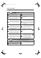
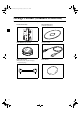
Vivid910-hard-E.book Page 8 Monday, October 18, 2004 3:11 PM Package Contents (Standard Accessories) Check that the following standard accessories are present.
Vivid910-hard-E.
Vivid910-hard-E.book Page 10 Monday, October 18, 2004 3:11 PM Optional Accessories When you need to purchase the following optional items, contact a KONICA MINOLTA SENSING-authorized service facility.
Vivid910-hard-E.
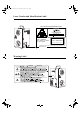
Vivid910-hard-E.book Page 12 Monday, October 18, 2004 3:11 PM Names and Functions of Parts Main Body Handle Light-Receiving Lens Note Power Switch Please keep the receiving lens cap and the laser barrier place in place when you are not carrying out scanning. Dust and scratches on the laser and lens can adversely affect scanning precision. Laser Emitting Window WARNING AC Power Connector A laser beam is emitted from this window. SCSI Port Do not stare into this window.
Vivid910-hard-E.book Page 13 Monday, October 18, 2004 3:11 PM Names and Functions of Parts Operation Panel 2 FOCUS AUTO 1 MENU SELECT CANCEL ENTER 3 1 FOCUS AUTO (Near) / 2 4 5 6 7 ..........................Focuses the image automatically. (Far)...........Focuses the image manually. indicates “far” and indicates “near”. .........................................Press once to display the menu on the viewfinder. Press again to close the menu and return to the monitor image. .................
Vivid910-hard-E.
Vivid910-hard-E.
Vivid910-hard-E.book Page 16 Monday, October 18, 2004 3:11 PM Connecting the AC Power Cord To ensure correct connection of the AC power cord, read the points given in WARNING and CAUTION carefully. WARNING Always use the AC power cord supplied as a standard accessory with the VIVID 9i, and connect it to an AC outlet (100-240 V , 50-60 Hz). Failure to do so may damage the VIVID 9i, causing a fire or electric shock. Do not bend, twist or pull the AC power cord excessively.
Vivid910-hard-E.book Page 17 Monday, October 18, 2004 3:11 PM Connecting the VIVID 9i to a Computer To operate the VIVID 9i from a computer using the Polygon Editing Tool, the VIVID 9i must be connected to the computer with an standard SCSI cable VI-A20. WARNING The computer must be operated correctly and safely according to its instruction manual. Memo • The standard SCSI cable has a 50-pin male plug (half-pitch, D-Sub) on both its ends. • It is also possible to use a commercially available USB adapter.
Vivid910-hard-E.book Page 18 Monday, October 18, 2004 3:11 PM Connecting the VIVID 9i to a Computer Setting the SCSI ID No. In order for the computer to recognize that the VIVID 9i is connected to the computer via the SCSI interface, a SCSI ID No. (0 to 6) must be set for the VIVID 9i. Memo SCSI ID No. 5 has been set as the default setting before shipment. Note If other devices are connected to the computer via the SCSI interface, make sure that the SCSI ID No.
Vivid910-hard-E.book Page 19 Monday, October 18, 2004 3:11 PM Connecting the VIVID 9i to a Computer Setting the Terminator The VIVID 9i has a built-in SCSI terminator. The terminator is required if the VIVID 9i is the last device of those connected in series to the SCSI interface (i.e., if only one of the SCSI ports on the VIVID 9i is used). If the terminator is not set correctly, the VIVID 9i or devices connected to the SCSI interface may malfunction.
Vivid910-hard-E.book Page 20 Monday, October 18, 2004 3:11 PM Connecting the VIVID 9i to a Computer 7 Press . Setting is now complete. Note To cancel the setting and return the SCSI SETTINGS screen to its original state, press 20 CANCEL .
Vivid910-hard-E.book Page 21 Monday, October 18, 2004 3:11 PM Starting and Quitting Starting the VIVID 9i [Operating Procedure] 1 Set the power switch to ON (“ ”). Power will be supplied to the VIVID 9i and initial setup is performed. After several dozen seconds, “PLEASE OPEN LASER BARRIER AND PRESS ANY KEY” will be displayed on the viewfinder. POWER AC IN SCSI Note When turning power ON again after it has been turned OFF, wait at least 5 seconds before doing so.
Vivid910-hard-E.book Page 22 Monday, October 18, 2004 3:11 PM Starting and Quitting 4 Press any key. The MONITOR view will appear, indicating that the VIVID 9i is now ready for operation.
Vivid910-hard-E.book Page 23 Monday, October 18, 2004 3:11 PM Starting and Quitting Quitting the VIVID 9i [Operating Procedure] 1 Set the power switch to OFF (“ Power will be turned OFF. ”). POWER AC IN 2 SCSI Attach the lens barrier. WARNING To ensure safety, please keep the lens barrier in place at all times when the unit is not in use. 3 Fit the lens cap onto the receiving lens.
Vivid910-hard-E.book Page 24 Monday, October 18, 2004 3:11 PM Mounting to the Tripod When using the instrument with the tripod, first attach the tripod attachment to the instrument, and then attach the instrument to the panhead/tripod. CAUTION • Make sure that the tripod attachment, panhead and tripod are secured to the instrument and each fastener on the tripod is firmly tightened. Failure to observe this point may result in the tripod overturning or the instrument dropping.
Vivid910-hard-E.book Page 25 Monday, October 18, 2004 3:11 PM Mounting to the Tripod 2. Mounting the Instrument to the Panhead After you have attached the tripod attachment to the instrument, they need to be mounted to the recommended panhead as explained below. First, remove the accessory plate from the panhead, attach it to the instrument, then attach both to the panhead. Memo Three screw holes are provided on the back of the tripod attachment, to allow mounting the tripod attachment to the panhead.
Vivid910-hard-E.
Vivid910-hard-E.
Vivid910-hard-E.book Page 28 Monday, October 18, 2004 3:11 PM Replacing the Lens and Field Calibration With the VIVID 9i, three types of lens are available: WIDE lens, MIDDLE lens and TELE lens. Be sure to mount the lens that best matches the subject’s size and distance. Before taking scans of a subject, most suitable lens for the size of the object and distance must be used. Note After changing the lens, you need to recalibrate using the field calibration system. For Field Calibration, refer to page 32.
Vivid910-hard-E.book Page 29 Monday, October 18, 2004 3:11 PM Replacing the Lens and Field Calibration Replacing Procedure You can use the status information to see what type of lens is currently attached. The lens type is also written on the lens itself. The explanation below assume that the power to the digitizer is ON, but note that it is also possible to change the lens while the power is OFF. If the power is OFF, however, you cannot use the digitizer’s viewfinder or control keys. Ref.
Vivid910-hard-E.book Page 30 Monday, October 18, 2004 3:11 PM Replacing the Lens and Field Calibration 3 Hold the external edge of the fixing ring and pull it out. Memo Hold the ring with your finger located near the red mark on the lens. This will facilitate pulling the lens. Note Attach the lens cap to the removed lens, place it in the lens case and keep it in a safe place. The following information will appear in the viewfinder as shown on the right.
Vivid910-hard-E.book Page 31 Monday, October 18, 2004 3:11 PM Replacing the Lens and Field Calibration 6 Attach the lens hood. Align the cutouts, and then turn clockwise. Memo The hood must be turned until it contacts the bayonet mount socket. 7 Press any key. After several dozen seconds, “PLEASE OPEN LASER BARRIER AND PRESS ANY KEY” will be displayed on the viewfinder. 8 Press any key. The viewfinder displays the monitor screen, and the digitizer is ready for use.
Vivid910-hard-E.book Page 32 Monday, October 18, 2004 3:11 PM Field Calibration The field calibration on this unit is done using the Field Calibration System. Periodic field calibration is recommended to maintain measurement precision. Note • Always carry out field calibration when changing lenses. • The Field Calibration System that corresponds to the type of lens the unit is equipped with must be used when conducting field calibration.
Vivid910-hard-E.book Page 33 Monday, October 18, 2004 3:11 PM Field Calibration • Installation Space A secure installation location that meets the dimensional requirements as shown in the drawing below is necessary to install the Field Calibration System. Before using the Field Calibration System, a “Calibration Area” for stable and high quality calibration is required, in addition to the place that is necessary to position the Field Calibration System. Approx. 73 cm Installation Space Approx.
Vivid910-hard-E.book Page 34 Monday, October 18, 2004 3:11 PM Field Calibration Executing Field Calibration The Field Calibration System is made up of the Field Calibration System Section and the Frame Section. It is necessary to assemble it when it is to be used for the first time or after it has been temporarily disassembled to move the Field Calibration System, etc. In addition, it is necessary to attach the Field Calibration System to the main unit in order to carry out field calibration.
Vivid910-hard-E.book Page 35 Monday, October 18, 2004 3:11 PM Field Calibration 2Turn the lock nut counterclockwise to unlock the rubber foot block. Memo Turn clockwise for lower heights and counterclockwise for higher heights. Note Because there is no preventive structure, moving the rubber foot block more than adjustable range may cause the rubber foot block to fall off. In this case, screw the rubber foot block onto the stopper unit clockwise. Adjust the height by turning the Rubber foot block.
Vivid910-hard-E.book Page 36 Monday, October 18, 2004 3:11 PM Field Calibration Field Calibration System Preparation There are two types of field calibration systems: one for WIDE lens type use and the other for MIDDLE/TELE lens type use. Use the Field Calibration System that corresponds to the type of lens the main unit is equipped with. [Procedure] • Preparing the Wide Lens Field Calibration System 1 Open the cover of the Field Calibration System Unit Section.
Vivid910-hard-E.book Page 37 Monday, October 18, 2004 3:11 PM Field Calibration Executing Field Calibration Field Calibration on this unit is carried out using the Polygon Editing Tool Software. After the assembly of the Field Calibration System has been completed and the unit connected to a PC and powered on, it will be necessary to start up the Polygon Editing Tool software. Note • Prevent foreign matter from getting into the “Calibration Area”.
Vivid910-hard-E.book Page 38 Monday, October 18, 2004 3:11 PM Field Calibration 4 At the [File] menu, select [Import-Digitizer], and click [One Scan] or [Step Scan]. The software opens the [File-Import-Digitizer-One Scan] or [File-Import-Digitizer-Step Scan] dialog. The dialog’s work window shows a field calibration image.
Vivid910-hard-E.book Page 39 Monday, October 18, 2004 3:11 PM Field Calibration 6 Check that field calibration was successful. If you are using field calibration results to measure the dimensions of the field calibration system, the software shows the differences from the measurements made at time of shipping. Differences are shown for four places: X1, Y1, X2, and Y2. • If field calibration was not successful, one of the following messages appears. Proceed in accordance with the displayed message.
Vivid910-hard-E.book Page 40 Monday, October 18, 2004 3:11 PM Field Calibration Ending Field Calibration After the field calibration is finished, remove the unit from the Field Calibration System. Also close the Field Calibration System that was used and return it to its original condition. [Procedure] 1 Remove the unit from the Attachment Section of the main unit. 2 Close the Field Calibration System.
Vivid910-hard-E.book Page 41 Monday, October 18, 2004 3:11 PM Field Calibration Disassembling the Field Calibration System In cases where the Field Calibration System needs to be disassembled to move or transport it or for reasons related to its installation space, separate the Field Calibration System into the Field Calibration System Unit and the Frame sections. Note Do not disassemble any sections that are not covered in this document. Doing so may lead to a reduction in precision.
Vivid910-hard-E.book Page 42 Monday, October 18, 2004 3:11 PM Adjusting the White Balance The color of an object varies slightly depending on the type of light source. To acquire accurate color image data, adjust the white balance as described below under the light source to be used. When scanning, we recommend that you use a stable, flicker-free light source (such as a high-frequency fluorescent lamp). Memo The white balance has been adjusted under fluorescent light before shipment.
Vivid910-hard-E.book Page 43 Monday, October 18, 2004 3:11 PM Adjusting the White Balance SELECT 5 Press (or ). The WHITE BALANCE view will appear. 6 Press as necessary to select one of the following settings. • DEFAULT: Adjusts for fluorescent light. ENTER WHITE BALANCE DEFAULT • USER’S: Uses the previously adjusted white balance. • CALIBRATION: Adjusts white balance automatically. 7 Press .
Vivid910-hard-E.book Page 44 Monday, October 18, 2004 3:11 PM Displaying the Status Information The model name, version, lens, field calibration system information can be displayed. [Operating Procedure] 1 2 Press . The MENU view will appear. STANDARD 3 HQ ON COLOR OFF W.B. SCSI Press FO”. to locate the arrow cursor to “IN- NF ON DEFAULT 5 ENABLED WHITE BALANCE INITIAL MODE INITIAL CONDITION SCSI SETTINGS →INFO 3 SELECT Press (or ). The status information will be displayed as shown below.
Vivid910-hard-E.book Page 45 Monday, October 18, 2004 3:11 PM Adjusting the Laser Power and CCD Gain Manually With certain objects, correct image data cannot be obtained. In this case, adjust the laser power and CCD gain as explained below. Adjustment must be made using the Polygon Editing Tool software. For information about how to proceed, refer to the software’s operation manual. Memo With the following objects, correct data may not be acquired, the laser power or CCD gain must be adjusted manually.
Vivid910-hard-E.book Page 46 Monday, October 18, 2004 3:11 PM Setting the Scan Mode The setting of scan mode can be set with Polygon Editing Tool software, and the setting is the top priority. It is not required to set by VIVID 9i. If you are not making scan settings from your PC’s software (for example, if using a customized program), please make the settings at the digitizer itself. Only settings are explained here. Note These settings become effective from the time of next start.
Vivid910-hard-E.
Vivid910-hard-E.book Page 48 Monday, October 18, 2004 3:11 PM Error Messages The following error messages appear if incorrect operation is performed or an abnormality occurs with the VIVID 9i. If an error message appears, take the appropriate corrective actions as shown in the table below. If the problem still does not disappear, contact a KONICA MINOLTA SENSING authorized service facility.
Vivid910-hard-E.book Page 49 Monday, October 18, 2004 3:11 PM Explanation of Measuring Principle Measuring Principle The VIVID 9i uses the light-stripe method to emit a horizontal stripe light through a cylindrical lens to the object. The reflected light from the object is received by the CCD, and then converted by triangulation into distance information. This process is repeated by scanning the stripe light vertically on the object surface using a Galvano mirror, to obtain a 3D image data of the object.
Vivid910-hard-E.book Page 50 Monday, October 18, 2004 3:11 PM Explanation of Measuring Principle High-Speed Image Processing Circuit The stripe light is scanned on the CCD image plane at one horizontal line per frame, and the CCD is driven so that the block readout start position is shifted one line per frame. Approximately 600 frames are acquired. · CCD drive rate: 12.5MHz · Block readout: 125 lines · Data acquisition speed: 2.5 sec.
Vivid910-hard-E.book Page 51 Monday, October 18, 2004 3:11 PM Dimension Diagram 18 412.5 474.5 (Unit: mm) 282.6 221 289.8 300.
Vivid910-hard-E.
Vivid910-hard-E.
Vivid910-hard-E.book Page 54 Monday, October 18, 2004 3:11 PM 9222-1750-11 © 2004 KONICA MINOLTA SENSING, INC.