
Universal Remote User Manual
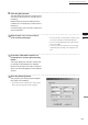
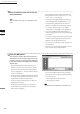
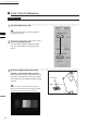
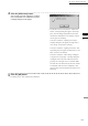
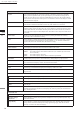
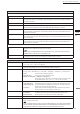

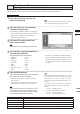
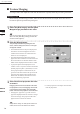
Table Of Contents
- Safety Symbols
- Notes on this Manual
- Trademarks
- About This Manual and Related Documents
- Safety Precautions
- Software Restrictions
- Notes On Use
- Notes On Storage
- Contents
- Conventions for Command Reference (Chapter 2)
- Chapter 1 Forward
- Chapter 2 Command Reference
- File Menu
- File – New
- File – Open
- File – Save – Elements
- File – Save – Scene
- File – Save as – Elements
- File – Save as – Scene
- File – Import – Elements
- File – Import – Digitizer – One Scan
- File – Import – Digitizer – Step Scan
- File – Import – Digitizer – One Scan
- File – Import – Digitizer – Step Scan
- File – Import – Digitizer – PC Card
- File – Import – Digitizer – PC Card
- File – Import – Digitizer – One Scan
- File – Import – Digitizer – Step Scan
- File – Import – Digitizer – PC Card
- File – Import – Digitizer – One Scan
- File – Import – Digitizer – Step Scan
- File – Import – Digitizer – Easy Align
- File – Import – Digitizer – PSC-1
- File – Export – Elements
- File – Export – Images
- File – Remove Elements
- File – Preferences
- File – Select Digitizer
- File – Exit
- View Menu
- Select Menu
- Edit Menu
- Build Menu
- Build – Registration – Initial – Manual
- Build – Registration – Initial – Auto
- Build – Registration – Fine – Elements
- Build – Registration – Fine – Points
- Build – Move – Points
- Build – Move – Elements
- Build – Move – To Origin
- Build – Move – To X-Y-Z
- Build – Rotate – Elements
- Build – Merge
- Build – Fill Holes – Manual
- Build – Fill Holes – Auto
- Build – Smooth – Element
- Build – Smooth – Points
- Build – Subsample – Uniformly – Element
- Build – Subsample – Uniformly – Points
- Build – Subsample – Adaptively – Element
- Build – Subsample – Adaptively – Points
- Build – Modify – Element
- Build – Modify – Points
- Build – Subdivision – Element
- Build – Subdivision – Points
- Build – Triangulate – Elements
- Build – Triangulate – Polygons
- Build – Texture Blending
- Build – Check Polygons – Element
- Build – Check Polygons – Polygons
- Info Menu
- Window Menu
- Tool Menu
- Pop-up Menus in Element View Window
- View Mode – Front/Right/Left/Back/Top/Bottom/Isometric/Perspective
- Rendering Mode – Wireframe/Shading/Texture Mapping/Wireframe+ Shading/Wireframe + Texture Mapping
- Show Vertex/Hide Vertex
- Show Normal/Hide Normal
- Show Axis/Hide Axis
- Smooth Shading/Flat Shading
- Select element from window
- Create clone window
- Close window
- Property
- Pop-up Menus in Element List
- Pop-up Menus in Image Window
- File Menu
- Chapter 3 Appendix
135
Chapter
2
File
Menu
910
File – Import – Digitizer – Easy Align
Parameters in the [File-Import-Digitizer-Easy Align] Dialog
Parameters Tab
Auto Maker Detection
Check this checkbox if using markers.
Settings
When you click this button, the button’s name changes to [Calibration]. You can then change
the color level and carry out calibration. This button appears only if the [Auto Maker Detection]
checkbox is checked
Color Level
Checking this checkbox sets the program to use color exposure level.
Calibration
If this checkbox is checked, the program gets a color image and generates a reference le from
it. This check box appears only if the [Auto Maker Detection] checkbox is checked.
Log
If this checkbox is checked, the program applies logarithmic correction to color data. Use if you
want to brighten up neutral colors. This check box appears only if the [Auto Maker Detection]
checkbox is unchecked.
Smooth
If this checkbox is checked, the program applies smoothing to color data. Use if illumination is
low and the image is unclear. This check box appears only if the [Auto Maker Detection] check-
box is unchecked.
Dark
If this checkbox is checked, the program applies dark correction to color data. Use if you are get-
ting striation-type noise in the images. This check box appears only if the [Auto Maker Detec-
tion] checkbox is unchecked.
Turntable Tab
Apply
When you click the [Apply] button after selecting the serial port and rotating stage, the [Angle]
slidebar becomes effective and stage control is enabled.
Note
IfconnectingtoaSKIDS-60YAWunit,select“CSG-602R(Ver.1.0)”fromthemenu.Ifconnectingtoa
SKIDS-60YAW(Ver.2.0)unit,select“CSG-602R(Ver.2.0)”.
Angle
The Angle slidebar becomes enabled when the program determines that the rotating stage is
operating normally. You can use the slidebar to control the stage’s rotation.
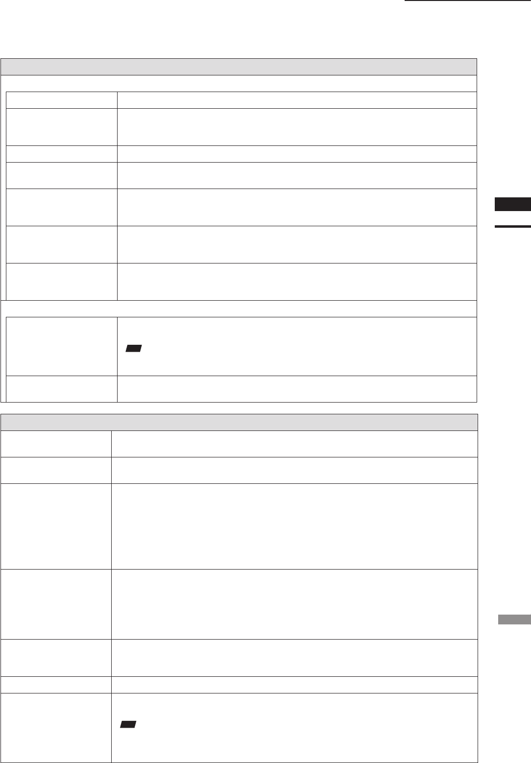
Parameters in the [File-Import-Digitizer-Easy Align-Convert] Dialog
Reduction Rate
Selects the reduction rate to be applied when importing data. You can select any of the following:
“1/1”, “1/4”, “1/9”, “1/16”, or “No polygon”.
Fill Holes
Selects whether the program lls in holes when importing the data. If the setting is On, the pro-
gram will automatically generate points to ll in holes left by missing data.
Remove
Selects which data the program excludes when carrying out the import. Select from any of the fol-
lowing: “None”, “Boundary (B.)”, “5deg. & B.”, “10deg &B.”, “15deg & B.”, or “20deg. & B.”
None: No removal when importing the data.
Boundary (B.): The program removes boundary points.
5deg & B., 10deg & B., 15deg. & B., 20deg. & B.:
The program removes boundary points and also removes polygons within
the specied angular range (5°,10°, 15°, or 20°) to the view vector.
Filter None: The program does not perform ltering when importing the data.
Noise Filter (N.F.): When importing data, the program corrects the points that appear to be noise.
High Quality (H.Q.): The program lters out unreliable data. (Effective only when importing
data that was scanned using the VIVID 910.)
H.Q & N.F.: Applies both noise lter and high quality lter. (Effective only when im-
porting data that was scanned using the VIVID 910.)
Marker Correction None: The program does not perform ltering the marker sections.
Cut marker: The data in the marker section will be deleted and treated as a hole.
Smooth marker: Smoothing will be carried out for the marker section data.
Use Texture
Check this checkbox when using texture.
Save Data
If you check this checkbox, the program will automatically save the data into a camera data le
when carrying out conversion.
Note
IfyouselectCDMastheletypeforthesave(attheSavedialogthatappears),theprogramwillnotincludethe
above-describeddatacorrectionsanddata-coordinateconversioninformationintothesavedle.Ifyouselecta
letypeotherthanCDM,however,theprogramdoesincorporatethisinformationintothesave.