
Universal Remote User Manual
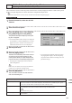
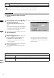
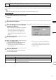
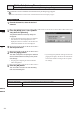
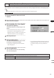
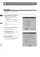
Table Of Contents
- Safety Symbols
- Notes on this Manual
- Trademarks
- About This Manual and Related Documents
- Safety Precautions
- Software Restrictions
- Notes On Use
- Notes On Storage
- Contents
- Conventions for Command Reference (Chapter 2)
- Chapter 1 Forward
- Chapter 2 Command Reference
- File Menu
- File – New
- File – Open
- File – Save – Elements
- File – Save – Scene
- File – Save as – Elements
- File – Save as – Scene
- File – Import – Elements
- File – Import – Digitizer – One Scan
- File – Import – Digitizer – Step Scan
- File – Import – Digitizer – One Scan
- File – Import – Digitizer – Step Scan
- File – Import – Digitizer – PC Card
- File – Import – Digitizer – PC Card
- File – Import – Digitizer – One Scan
- File – Import – Digitizer – Step Scan
- File – Import – Digitizer – PC Card
- File – Import – Digitizer – One Scan
- File – Import – Digitizer – Step Scan
- File – Import – Digitizer – Easy Align
- File – Import – Digitizer – PSC-1
- File – Export – Elements
- File – Export – Images
- File – Remove Elements
- File – Preferences
- File – Select Digitizer
- File – Exit
- View Menu
- Select Menu
- Edit Menu
- Build Menu
- Build – Registration – Initial – Manual
- Build – Registration – Initial – Auto
- Build – Registration – Fine – Elements
- Build – Registration – Fine – Points
- Build – Move – Points
- Build – Move – Elements
- Build – Move – To Origin
- Build – Move – To X-Y-Z
- Build – Rotate – Elements
- Build – Merge
- Build – Fill Holes – Manual
- Build – Fill Holes – Auto
- Build – Smooth – Element
- Build – Smooth – Points
- Build – Subsample – Uniformly – Element
- Build – Subsample – Uniformly – Points
- Build – Subsample – Adaptively – Element
- Build – Subsample – Adaptively – Points
- Build – Modify – Element
- Build – Modify – Points
- Build – Subdivision – Element
- Build – Subdivision – Points
- Build – Triangulate – Elements
- Build – Triangulate – Polygons
- Build – Texture Blending
- Build – Check Polygons – Element
- Build – Check Polygons – Polygons
- Info Menu
- Window Menu
- Tool Menu
- Pop-up Menus in Element View Window
- View Mode – Front/Right/Left/Back/Top/Bottom/Isometric/Perspective
- Rendering Mode – Wireframe/Shading/Texture Mapping/Wireframe+ Shading/Wireframe + Texture Mapping
- Show Vertex/Hide Vertex
- Show Normal/Hide Normal
- Show Axis/Hide Axis
- Smooth Shading/Flat Shading
- Select element from window
- Create clone window
- Close window
- Property
- Pop-up Menus in Element List
- Pop-up Menus in Image Window
- File Menu
- Chapter 3 Appendix
209
Chapter
2
Build
Menu
9i
910
900
700
300
Build – Subsample – Adaptively – Points
Reducing the Selected Points Adaptively
This command is used to reduce the points selected in the currently displayed element so that surface points
density in simple-shaped areas is lower than that in complicated-shaped areas.
M
emo
The elements selected before execution of this command will be divided to triangular polygons.
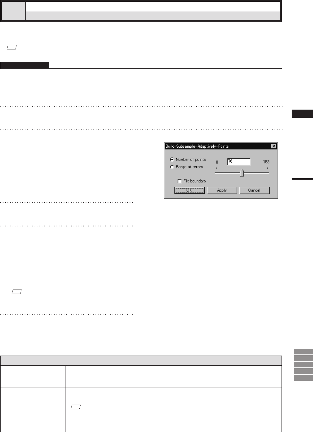
Parameters for [Build-Subsample-Adaptively-Points] Dialog Box
Number of points
Reduces the current number of points to the specied number. When the [Apply] button is clicked,
the current number of vertices will be displayed. (The default for the “Number of points” param-
eter is set so that the number of selected points will be reduced by 50%.)
Range of errors
The program reduces data in accordance with the value that you enter. The value serves as a gen-
eral yardstick for the amount of reduction-induced change in model tolerance.
M
emo
The default setting is “0.2”.
Fix boundary
Among the selected points, the points present on the boundary of the hole will be excluded from
data reduction.
Operating Procedure
1
From the element list, select one desired
element.
2
Select the desired points.
3
From the [Build] menu, select [Subsam-
ple] –[Adaptively] then click [Points].
The [Build-Subsample-Adaptively-Points] dia-
log box will appear.
• The selected element will be ready to be displayed
in all windows. It will be displayed if it is not dis-
played in the active window or the windows for
which all the elements are set to be displayed.
4
Set the parameters.
5
Click the [Apply] button.
The data of the selected points will be reduced
according to the parameter settings so that
surface points density in simple-shaped areas
is lower than that in complicated-shaped areas.
• The polygons comprising the selected element
will be triangulated.
• If you change the parameter settings and click
the [Apply] button again, the data comprising
the points will be reduced according to the new
parameter settings.
M
emo
In some cases, the number of vertices present after data
reduction may not match the specied number.
6
Click the [OK] button.
This will conrm execution of data reduction
and close the dialog box.