
Universal Remote User Manual
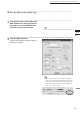
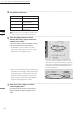
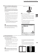
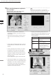
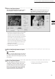
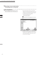
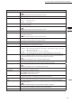
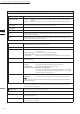
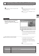
Table Of Contents
- Safety Symbols
- Notes on this Manual
- Trademarks
- About This Manual and Related Documents
- Safety Precautions
- Software Restrictions
- Notes On Use
- Notes On Storage
- Contents
- Conventions for Command Reference (Chapter 2)
- Chapter 1 Forward
- Chapter 2 Command Reference
- File Menu
- File – New
- File – Open
- File – Save – Elements
- File – Save – Scene
- File – Save as – Elements
- File – Save as – Scene
- File – Import – Elements
- File – Import – Digitizer – One Scan
- File – Import – Digitizer – Step Scan
- File – Import – Digitizer – One Scan
- File – Import – Digitizer – Step Scan
- File – Import – Digitizer – PC Card
- File – Import – Digitizer – PC Card
- File – Import – Digitizer – One Scan
- File – Import – Digitizer – Step Scan
- File – Import – Digitizer – PC Card
- File – Import – Digitizer – One Scan
- File – Import – Digitizer – Step Scan
- File – Import – Digitizer – Easy Align
- File – Import – Digitizer – PSC-1
- File – Export – Elements
- File – Export – Images
- File – Remove Elements
- File – Preferences
- File – Select Digitizer
- File – Exit
- View Menu
- Select Menu
- Edit Menu
- Build Menu
- Build – Registration – Initial – Manual
- Build – Registration – Initial – Auto
- Build – Registration – Fine – Elements
- Build – Registration – Fine – Points
- Build – Move – Points
- Build – Move – Elements
- Build – Move – To Origin
- Build – Move – To X-Y-Z
- Build – Rotate – Elements
- Build – Merge
- Build – Fill Holes – Manual
- Build – Fill Holes – Auto
- Build – Smooth – Element
- Build – Smooth – Points
- Build – Subsample – Uniformly – Element
- Build – Subsample – Uniformly – Points
- Build – Subsample – Adaptively – Element
- Build – Subsample – Adaptively – Points
- Build – Modify – Element
- Build – Modify – Points
- Build – Subdivision – Element
- Build – Subdivision – Points
- Build – Triangulate – Elements
- Build – Triangulate – Polygons
- Build – Texture Blending
- Build – Check Polygons – Element
- Build – Check Polygons – Polygons
- Info Menu
- Window Menu
- Tool Menu
- Pop-up Menus in Element View Window
- View Mode – Front/Right/Left/Back/Top/Bottom/Isometric/Perspective
- Rendering Mode – Wireframe/Shading/Texture Mapping/Wireframe+ Shading/Wireframe + Texture Mapping
- Show Vertex/Hide Vertex
- Show Normal/Hide Normal
- Show Axis/Hide Axis
- Smooth Shading/Flat Shading
- Select element from window
- Create clone window
- Close window
- Property
- Pop-up Menus in Element List
- Pop-up Menus in Image Window
- File Menu
- Chapter 3 Appendix
62
Chapter
2
File
Menu
910
File – Import – Digitizer – Step Scan (When VIVID 910 is Selected)
10
Click the [Scan] button to acquire the
first scan data.
A scan will start, and a color image will be
displayed in the Work window area.
M
emo
If [Use Color] is not checked (i.e. no check mark is
shown), the scan data has no color image data, and a gray-
scale image will be displayed instead of a color image.
• If the [Auto Scan] checkbox is checked, the
second and subsequent scans will be carried out
automatically.
• If the [Auto Store] checkbox is checked, a store
will be carried out automatically at the end of
scan.
• Clicking on the following radio buttons will
make a change to the image displayed in the work
window. The data acquired during the scan will
remain unchanged.
Item Explanation
[Mono] radio
button
The current image is displayed in
monochrome.
[Color] radio
button
The color image acquired from
the scan is displayed.
[Pitch] radio
button
The distance data is displayed
in the color that is shown in the
Near-Far color slide bar ac-
cording to the distance from the
object to the digitizer.
• Clicking the [Color Read] button will re-scan for
the color data only. The distance data will not be
updated.
• Clicking the [Edit] button enables you to delete
the area that is not necessary for three-dimen-
sionalization by specifying it using the mouse.
Messages will appear at the bottom of the Work
window area as shown right, so follow them to
operate the mouse.
Click the [Edit] button again to exit the edit mode.
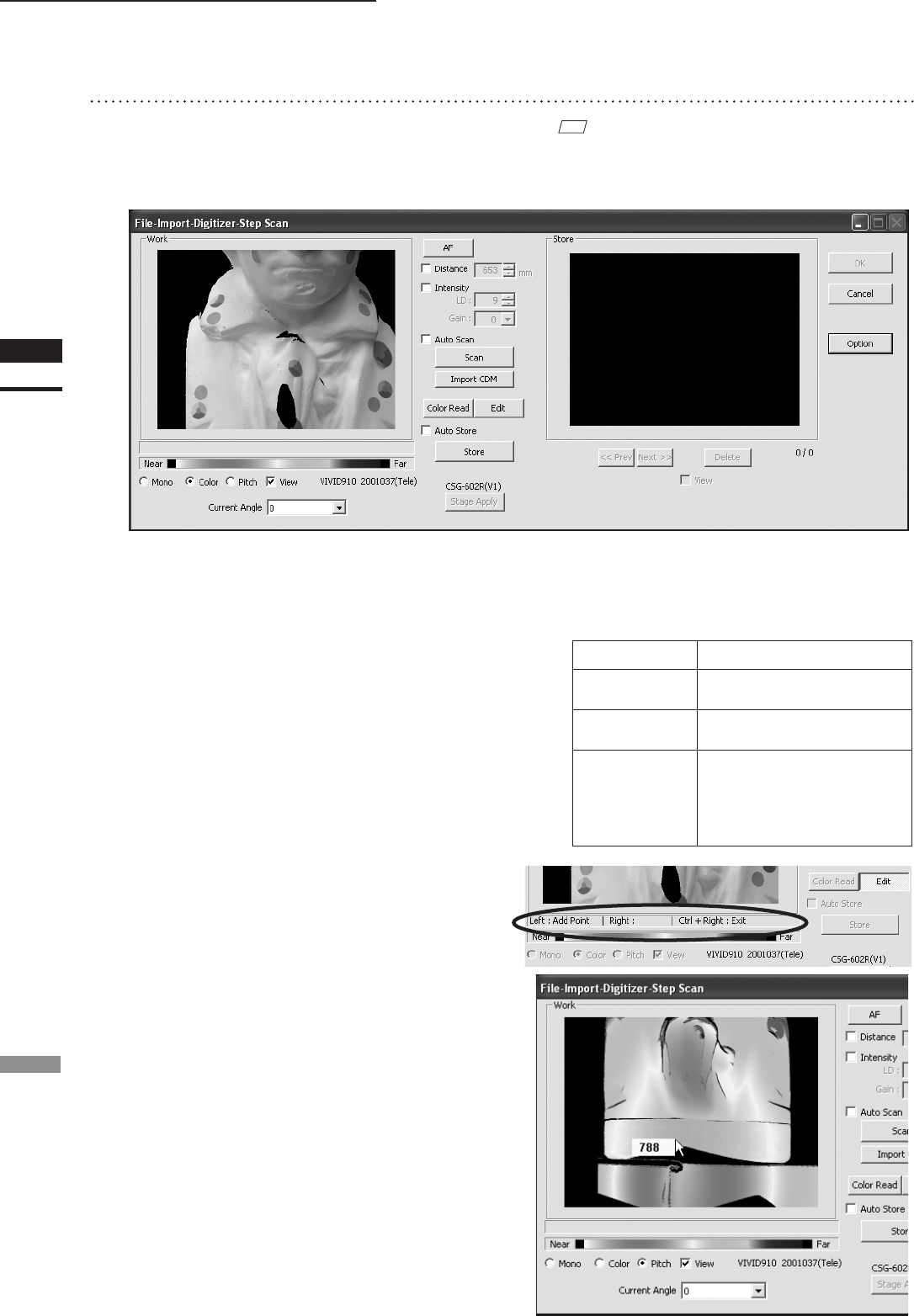
• Switch to pitch display screen, and right-click on
desired position in the screen while holding down
[CTRL] key. The Z-axis coordinates at that posi-
tion (distance from VIVID 910) will appear.
To specify distance manually and perform mea-
surement, this value must be used.