Polygon Editing Tool Instruction Manual
n Safety Symbols The following symbols are used in this manual to prevent accidents which may occur as result of incorrect use of the instrument. Denotes a sentence regarding safety warning or note. Read the sentence carefully to ensure safe and correct use. Denotes a prohibited operation. The operation must never been performed. Denotes an instruction. The instruction must be strictly adhered to. Denotes a sentence regarding safety precaution for laser.
Instruction manual for each model in the VIVID series of non-contact 3D digitizers VIVID digitizers offers rapid, high-precision 3D scanning ideal for imaging of industrial products in a wide range of shapes and configurations. This manual describes the digitizer’s features and operating procedures, and calls attention to relevant precautions. Photogrammetry System Explains the PSC-1 system, a high-precision alignment system based on photographic measurement technology.
Contents Safety Precautions............................................................................................................................................... 1 Software Restrictions........................................................................................................................................... 1 Notes On Use.......................................................................................................................................................
• View Menu View Orbit Zoom Full Frame All Full Frame Displaying Area Orbit Area Zoom Move Plane Move Light Camera Settings Image Show Element List/Hide Element List Show Toolbar Rotating or moving the Camera Position Enlarging/Reducing the Displayed Item Displaying Data Fully in all Windows Data Fully in Active Window Rotating the Camera and Setting the Rotation Center Enlarging/Reducing Item Enclosed by Specified Rectangle Setting Display Depth Moving the Light Setting the C
• Build Menu Build Registration Initial Manual Performing Initial Registration of Elements Manually Auto Performing Initial Registration of Elements Automatically Fine Elements Performing Fine Registration of Elements Points Performing Fine Registration of Selected Points Move Points Moving the Selected Points Elements Moving Element (s) To Origin Moving the Element (s) to the Origin To X-Y-Z Converting the Coordinate System of Element Rotate Elements Rotating Element
• Pop-up Menus in Element view window View Mode Front/Right/Left/Back/Top/Bottom/Isometric/Perspective Changing View Mode Rendering Mode Wireframe/Shading/Texture Mapping/Wireframe + Shading/Wireframe + Texture Mapping Changing Rendering Mode Show Vertex/Hide Vertex Showing or Hiding Vertices Show Normal/Hide Normal Showing or Hiding Normal Vectors Show Axis/Hide Axis Showing or Hiding Axes Smooth Shading/Flat Shading Changing Shading Mode Select element from window
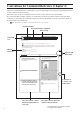
Conventions for Command Reference (Chapter 2) Chapter 2 “Command Reference” (from page 21) gives an explanation of the function and operating procedure of each command in the menu order. The shortcut key and the icon (displayed on the tool bar) are also shown in the command title. We recommend that you make extensive use of shortcut keys when running this software.
Chapter 1 Chapter 1 Preparations Regarding the software Uninstalling Forward Chapter 1 explains the preparations for using Polygon EditingTool. The method for uninstalling the software from the computer is also explained. Preparations 1) Introduction of Operating Conditions.....................................8 2) Attaching the protect key to the computer.............................9 3) Installing the ASPI driver software on the computer............
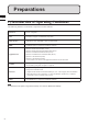
Preparations Chapter 1 Preparations 1) Introduction of Operating Conditions The following hardware environment is required to run this software. Hardware PC/AT compatible CPU Piuentm 4 or higher recommended (only Intel) Main memory 1024 MB or more (2048 MB or more recommended) HDD 15 MB free space is required to install this software.
2) Connecting the protect key to the computer When using Polygon Editing Tool, it is necessary to attach the protect key and install the protect key (HASP) driver to the computer before installing Polygon Editing Tool. Attach the protect key to the computer correctly according to the following procedure. Chapter Memo The installation procedure is also given in the “README_E.txt” file in the “Polygon Editing Tool” directory of the software’s CD-ROM.
3) Installing the ASPI driver software to the computer Chapter 1 Preparations The software uses SCSI as the interface connecting the VIVID and the computer. For the computer to recognize VIVID correctly, it is necessary to install the ASPI driver software on the computer. * Even if the VIVID will not be connected to the computer, it is still necessary to install the ASPI driver. Note When Windows Vista or Windows 7 is used, it is necessary to install the driver software of the RATOC Systems Inc.’s USB2.
4) Installing Polygon Editing Tool on the computer When installing the software, make sure to install it correctly according to the following procedure. Memo It is necessary to connect the protect key to the computer correctly before installing the software. If the protect key has not yet been connected, connect the protect key to the computer according to the procedure on page 9. Chapter Operating Procedure 1 Start Windows and insert the software CD-ROM into the CD-ROM drive.
Chapter 5 Click the [NEXT] button and click the [Install] button. 6 Follow the instructions displayed on the screen to complete installation. 1 Preparations The Polygon Editing Tool will be installed. When installation is completed successfully, the following files will be created in the directory where the software has been installed. KONICA MINOLTA Polygon Editing Tool Ver.*.** Bin PET.exe • • • Plugin AddTexture.
5) Connecting the VIVID digitizer to the computer When the VIVID digitizer will be controlled from Polygon Editing Tool, connect the VIVID digitizer to the computer first, and then start up Polygon Editing Tool. The first time the VIVID digitizer is connected to the computer, it is necessary for the computer to recognize the VIVID digitizer as an external device. Perform operations according to the following procedure.
n Recognition of the VIVID digitizer by the computer The first time the VIVID digitizer is connected to the computer, cause the computer to recognize the VIVID digitizer as an external device by following the procedure below. Note Chapter It is not necessary to install the device driver of the VIVID digitizer on the computer; however, Polygon Editing Tool cannot control the digitizer until recognition has been completed.
4 When a dialog for specifying the desired driver search method appears, check the “Search for the best driver in these locations.” radio button, clear any other checkbox for specifying the location, and then click “Next”. 5 If a dialog with the message “Cannot Install this Hardware” appears, check the “Don’t prompt me again to install this software.” checkbox and then click “Finish”. 6 Start the device manager to confirm whether or not the VIVID digitizer has been properly recognized by the computer.
Regarding the software Chapter 1 Regarding the software 1) Starting and Quitting the Software n Starting the Software Operating Procedure 1 From the [Start] menu, select [Program] –[KONICA MINOLTA], and then click [Polygon Editing Tool Ver.*.**]. The Polygon Editing Tool will start. • If a scene file with the name “startup.scn” currently exists in the directory named “Polygon Editing Tool Ver.*.**” Model”, the program will automatically load this file as it starts up.
2) Main Window 1. Title bar 2. Menu bar 3. Tool bar 4. Element list Chapter 1 Regarding the software 5. Window tile 6. Element view window 7. Status bar 1. Title bar �������������������������� Displays the file name of the currently displayed image data. 2. Menu bar ����������������������� Used to select various functions of this software. 3. Tool bar ������������������������� Displays the icons of the frequently used commands. Clicking an icon will execute the corresponding command. 4.
n Toolbar Icons Chapter 1 Regarding the software Icon Command Reference Page File – Open Open an element file or scene file. 24 File – Save – Elements Saves element data. 26 File – Import – Digitizer – One Scan Reads in the data from a 1-shot scan by the digitizer. File – Import – Digitizer – Step Scan File – Import – Digitizer – PSC-1 18 Description Reads in the data from a step-shot scan by the digitizer.
Uninstalling Chapter 1 1) Uninstalling the Polygon Editing Tool To uninstall the software, use the standard uninstall program of Windows. Uninstalling Remarks The software will be deleted one folder at a time. If you have a file(s) you want to keep, copy it to another folder before starting uninstallation. Operating Procedure 1 From the [Start] menu, select [Setting] and then click [Control Panel]. The [Control Panel] window will appear.
2) Uninstalling the Protect Key Driver Chapter To uninstall the protect key driver, use the standard uninstall program of Windows. 1 Memo Before uninstalling the protect key driver, make sure that the protect key is removed from the computer. Uninstalling Operating Procedure 1 Remove the protect key from the computer’s USB port. 2 From the [Start] menu, select [Setting] and then click [Control Panel]. The [Control Panel] window will appear.
Chapter 2 Command Reference Chapter 2 explains the functions of Polygon Editing Tool, using as keywords the commands that can be selected from the menus of the main window and/or icons of the toolbar. In addition, the scanning procedure for storing 3-dimensional data by controlling the digitizer from Polygon Editing Tool is also explained.
22
File Menu New…………………………………………………………………………………………24 Open… ……………………………………………………………………………………24 Save – Elements……………………………………………………………………………26 Save – Scene… ……………………………………………………………………………27 Save as – Elements…………………………………………………………………………28 Chapter File Menu Save as – Scene… …………………………………………………………………………29 Import – Elements… ………………………………………………………………………30 Import – Digitizer – One Scan • When VIVID 9i is Selected … ……………………………………………………33 • When VIVID 910 is Selected………………………………………………………50 • When VIVID 900/910 is Sel
File – New [Ctrl] + [N] Creating New Scene Data This command is used to delete the current scene and open a new scene. Operating Procedure 1 Chapter Click [New] on the [File] menu. The current scene will be deleted and a new blank scene will be generated. • If modifications have been made to an element after it has been imported or saved, the “Some elements are modified. Do you want to save them?” message dialog box will appear. 2 File Menu • To save the element data, click the [Yes] button.
File – Open 2 Select the file you want to load. If you select an element file with an attached image and you have also checked the Preview box, the display area will show a preview image. • To display files of a certain format only, select the desired format from the [File of type] pull-down menu. Note • It is not possible to select files of different formats. • In the case of scene files, only one file can be opened.
File – Save – Elements [Ctrl] + [S] Saving Element Data This command is used to save the data selected in the element list. The data will be saved under the current element file name. Operating Procedure 1 Chapter 2 File Menu 2 From the element list, select the element(s) to be saved. Memo It is possible to select two or more elements by clicking them while holding down the [Shift] or [Ctrl] key. From the [File] menu, select [Save] and then click [Elements].
File – Save – Scene Saving Scene Data This command is used to save the current scene data under the current scene file name. Operating Procedure 1 From the [File] menu, select [Save] and then click [Scene]. The elements comprising the scene and its view information will be saved under the current scene file name. • If the scene is one that has been newly created, the same dialog box as the one that appears when the File – Save as – Scene command is selected will appear.
File – Save as – Elements Saving Element Data under a Different Name This command is used to save the data selected in the element list under a different file name. Operating Procedure 1 2 Chapter From the element list, select the element to be saved. Memo It is possible to select two or more elements by clicking them while holding down the [Shift] or [Ctrl] key. From the [File] menu, select [Save as] and then click [Elements]. The [File-Save as-Elements] dialog box will appear.
File – Save as – Scene Saving Scene Data under a Different Name This command is used to save the current scene data under a different file name. Operating Procedure 1 From the [File] menu, select [Save as] and then click [Scene]. The [File-Save as-Scene] dialog box will appear. 2 Enter the desired file name, and click the [Save] button. The scene comprising the elements and its view information will be saved.
File – Import – Elements Importing Scanned Data This command is used to import the raw scan data that was saved when the object was scanned by the VIVID (VI) series digitizer. Operating Procedure 1 Chapter From the [File] menu, select [Import] and then click [Elements]. The [File-Import-Elements] dialog box will appear. • The dialog box shows a list of files. If all the files cannot be displayed on one page, a scroll bar will be displayed.
File – Import – Elements • When importing data, if you want to perform dark correction for color data, check the [Dark Correction] checkbox. • When importing data, if you want to perform log correction for color data, check the [Log Correction] checkbox. 5 Click the [Import] button. The data will be imported and displayed in the element view window. The names of the imported elements will also appear in the element list, indicating that the elements have been selected (highlighted).
File – Import – Elements Parameters for [File-Import-Elements] Dialog Box Look in Select the folder containing the element file to import. File name File name selected on the list is displayed. File of type Data format of the selected file is displayed. Reduction Rate Selects the reduction rate to be applied when importing the data. You can select any of the following: “1/1”, “1/4”, “1/9”, “1/16”, or “No polygon”, “Adaptive”. Note Selecting “Adaptive” reduces data adaptively.
File – Import – Digitizer – One Scan (When VIVID 9i is Selected) Performing One Scan with the VIVID 9i This command is used to cause the VIVID 9i (VI-9i) to scan the object one scan at a time using the remote control function of this software. Registration of multiple scan data can be performed by manually designating their corresponding points. Once registration is complete, the data can be saved together with the coordinate conversion parameters provided for registration as a single data file (CDK).
File – Import – Digitizer – One Scan (When VIVID 9i is Selected) Chapter 2 File Menu 3 Set an object in place. 4 To display the object in the middle of the Work window area, change the position of the object or move the instrument back and forth to change the view angle. If you are going to use the rotating stage, place the object on it. 5 Click the [Option] button. 6 Set optional parameters. Memo If necessary, replace the lens attached to the instrument.
File – Import – Digitizer – One Scan (When VIVID 9i is Selected) 8 Click the [Scan] button to acquire the first scan data. A scan will start, and a color image will be displayed in the Work window area. Memo If [Use Color] is not checked (i.e. no check mark is shown), The scan data has no color image data, and a grayscale image will be displayed instead of a color image. Chapter File Menu • Clicking on the following radio buttons will make a change to the image displayed in the Work window area.
File – Import – Digitizer – One Scan (When VIVID 9i is Selected) 9 Chapter Click the [Store] button. The color data displayed in the Work window area will appear in the Store Window area. Note The [Store] button will be disabled (displayed in gray) when clicked once. This will prevent the same Work window area’s data from being stored repeatedly. 2 File Menu 10 Acquire the second scan data.
File – Import – Digitizer – One Scan (When VIVID 9i is Selected) the [Scan] button. 11 Click At this time, the data in the Work window area does not correspond to the one in the Store window area, so a red frame is displayed. RED Chapter File Menu 12 Designate three or more corresponding Memo points. Set the corresponding points in the Work window area and then store window alternately. When the corresponding points have been designated properly, the red frame will turn to blue.
File – Import – Digitizer – One Scan (When VIVID 9i is Selected) 13 Click the [Store] button. The data displayed in the Work window area will appear in the Store window area. If the corresponding points have been properly designated, all the stored data will be displayed in 3-D in the element view window after it is registrated and three-dimensionalized. Chapter 2 File Menu • This step is not necessary if the [Auto Store] checkbox has been checked.
File – Import – Digitizer – One Scan (When VIVID 9i is Selected) Parameters for [File-Import-Digitizer-One Scan] Dialog Box AF Executes auto-focus. Note This parameter is effective only when VIVID 9i is connected. Distance Checking this checkbox enables distance setting. Note This parameter is effective only when VIVID 9i is connected. Intensity Checking this checkbox enables LD and Gain setting. • LD: Sets the laser power. • Gain: Sets the gain.
File – Import – Digitizer – One Scan (When VIVID 9i is Selected) Parameters for [File-Import-Digitizer-One Scan-Option] Dialog Box Scan Parameter Chapter 2 File Menu Mode • Standard:The Filter settings are fixed to H.Q. & N.F. The settable distance range is from 600 to 1,000 mm. The Gain value is fixed at 0. • Extend: The Filter settings are fixed to Noise Filter (N.F.). The settable distance range is from 500 to 2,500 mm. • User: The Filter settings can be user-defined.
File – Import – Digitizer – Step Scan (When VIVID 9i is Selected) Performing Step Scan with the VIVID 9i This command is used to cause the VIVID 9i to make multiple shots of the object by controlling the rotary stage remotely from this software. Registration of multiple scan data can be performed using the Calibration Chart for extract center of rotation.
File – Import – Digitizer – Step Scan (When VIVID 9i is Selected) Chapter 2 File Menu 3 Place the object on the rotating stage. 4 To display the object in the middle of the Work window area, change the position of the object or move the VIVID 9i back and forth to change the view angle. 5 Memo If necessary, replace the lens attached to the VIVID 9i. If the lenses are changed, carry out field calibration using the Field Calibration System. Click the [Option] button.
File – Import – Digitizer – Step Scan (When VIVID 9i is Selected) 6 Set optional parameters. Item Explanation Scan Parameter Sets the settings for scanning. Convert Parameter Sets the settings for threedimensionalization. Select the rotary stage to be used. Clicking this restores the default settings. Stage Parameter [Default] button Ref. For details, refer to the parameters (P.49) for [File- Chapter Import-Digitizer-Step Scan-Option] dialog box.
File – Import – Digitizer – Step Scan (When VIVID 9i is Selected) 9 Place the Calibration Chart on the rotating stage and scan the Calibration Chart. Calibration chart S Position the chart with the black line facing the VIVID, and place it on the rotating stage so that both entire side surfaces are observed in the viewfinder. Chapter 2 File Menu • This step is not necessary if the Calibration Chart data has already been imported when this dialog box is opened.
File – Import – Digitizer – Step Scan (When VIVID 9i is Selected) 11 Click the [Scan] button to acquire the first scan data. Memo A scan will start, and a color image will be displayed in the Work window area. If [Use Color] is not checked (i.e. no check mark is shown), The scan data has no color image data, and a grayscale image will be displayed instead of a color image. Chapter File Menu • If the [Auto Scan] checkbox is checked, the second and subsequent scans will be carried out automatically.
File – Import – Digitizer – Step Scan (When VIVID 9i is Selected) on the [Store] button. 12 Click The color data displayed in the Work window area will appear in the Store window area. Chapter Note The [Store] button will be disabled (displayed in gray) when clicked once. This will prevent the same work window area’s data from being stored repeatedly.
File – Import – Digitizer – Step Scan (When VIVID 9i is Selected) 15 Repeat Steps 13 to 14 until the desired corresponding points are designated. the [OK] button. 16 Click The data displayed in the element view window by the Store function will remain as is. • If [Save Raw Data] checkbox in [File-Import -Digitizer-Step Scan-Option] dialog box has been checked, [Save As] dialog box will be displayed.
File – Import – Digitizer – Step Scan (When VIVID 9i is Selected) Parameters for [File-Import-Digitizer-Step Scan] Dialog Box AF Executes auto-focus. Note This parameter is effective only when VIVID 9i is connected. Distance Checking this checkbox enables distance setting. Intensity Checking this checkbox enables LD and Gain setting. • LD: • Gain: Auto Scan Scan Chapter Checking this checkbox causes scan, store and stage control operations to be automatically performed sequentially. Performs a scan.
File – Import – Digitizer – Step Scan (When VIVID 9i is Selected) Parameters for [File-Import-Digitizer-Step Scan-Option] Dialog Box Scan Parameter Mode • Standard: • Extend: • User: Digitizer’s Parameter • GET: • SET: The Filter settings are fixed to H.Q. & N.F. The settable distance range is from 600 to 1,000 mm. The Gain value is fixed at 0. The Filter settings are fixed to Noise Filter (N.F.). The settable distance range is from 500 to 2,500 mm.
File – Import – Digitizer – One Scan (When VIVID 910 is Selected) Performing One Scan with the VIVID 910 This command is used to cause the VIVID 910 (VI-910) to scan the object one scan at a time using the remote control function of this software. Registration of multiple scan data can be performed by manually designating their corresponding points. Warning Never stare into the laser emitting window. Do not place a lens, mirror or optical element in the passage of the laser beam.
File – Import – Digitizer – One Scan (When VIVID 910 is Selected) 4 Click the [Option] button. 5 Set optional parameters. The [File-Import-Digitizer-One Scan-Option] dialog box will appear. Item Explanation Scan Parameter Sets the settings for scanning. Convert Parameter Sets the settings for threedimensionalization. Select the rotary stage to be used. Clicking this restores the default settings. Stage Parameter [Default] button Chapter File Menu Ref. For details, refer to parameters (P.
File – Import – Digitizer – One Scan (When VIVID 910 is Selected) 7 Click on the [Scan] button to acquire the first scan data. A scan will start, and a color image will be displayed in the Work window area. Chapter Memo If [Use Color] is not checked (i.e. no check mark is shown), the scan data has no color image data, and a grayscale image will be displayed instead of a color image. 2 File Menu • Clicking on the following radio buttons will make a change to the image displayed in the work window.
File – Import – Digitizer – One Scan (When VIVID 910 is Selected) 8 Click on the [Store] button. The color data displayed in the Work window area will appear in the Store window area. Note The [Store] button will be disabled (displayed in gray) when clicked once. This will prevent the same Work window area’s data from being stored repeatedly. Chapter File Menu 9 Acquire the second scan data.
File – Import – Digitizer – One Scan (When VIVID 910 is Selected) on the [Scan] button. 10 Click At this time, the data in the Work window area does not correspond to the one in the Store window area, so a red frame is displayed. Chapter RED 2 File Menu 11 Designate three or more corresponding points. Set the corresponding points in the work window and then store window alternately. When the corresponding points have been designated properly, the red frame will turn to blue.
File – Import – Digitizer – One Scan (When VIVID 910 is Selected) 12 Click on the [Store] button. The data displayed in the Work window area will appear in the Store window area. If the corresponding points have been properly designated, all the stored data will be displayed in 3-D in the element view window after it is registrated and three-dimensionalized. • This step is not necessary if the [Auto Store] checkbox has been checked.
File – Import – Digitizer – One Scan (When VIVID 910 is Selected) Parameters for [File-Import-Digitizer-One Scan] Dialog Box AF Executes auto-focus. Note This parameter is effective only when VIVID 910 is connected. Distance Checking this checkbox enables distance setting. Note This parameter is effective only when VIVID 910 is connected. Intensity Checking this checkbox enables LD and Gain setting. • LD : Sets the laser power. • Gain : Sets the gain.
File – Import – Digitizer – One Scan (When VIVID 910 is Selected) Parameters for [File-Import-Digitizer-One Scan-Option] Dialog Box Scan Parameter Mode • Select the scanning mode : FINE or FAST Scan Parameter • Load : • Save : Brightness Checking this checkbox enables you to set the brightness of the image. Use Color Checking this checkbox takes a color shot when a scan is made. Log Performs log correction for the color data if this checkbox is checked.
File – Import – Digitizer – Step Scan (When VIVID 910 is Selected) Performing Step Scan with the VIVID 910 This command is used to cause the VIVID 910 (VI-910) to make multiple shots of the object by controlling the rotary stage remotely from this software. Registration of multiple scan data can be performed using the Calibration Chart for extract center of rotation. Warning Never stare into the laser emitting window. Do not place a lens, mirror or optical element in the passage of the laser beam.
File – Import – Digitizer – Step Scan (When VIVID 910 is Selected) 2 Place the object on the rotating stage. 3 To display the object in the middle of the Work window area, change the position of the object or move the VIVID 9i back and forth to change the view angle. Memo If necessary, replace the lens attached to the VIVID 910. Chapter File Menu 4 Click the [Option] button. The [File-Import-Digitizer-Step Scan-Option] dialog box will appear.
File – Import – Digitizer – Step Scan (When VIVID 910 is Selected) 5 Set optional parameters. Item Scan Parameter Sets the settings for scanning. Convert Parameter Sets the settings for threedimensionalization. Select the rotary stage to be used. Clicking this restores the default settings. Stage Parameter [Default] button Chapter 2 Explanation Ref. For details, refer to the parameters (P.66) for [File- Import-Digitizer-Step Scan-Option] dialog box.
File – Import – Digitizer – Step Scan (When VIVID 910 is Selected) 8 Place the Calibration Chart on the rotating stage and scan the Calibration Chart. Calibration chart S Position the chart with the black line facing the VIVID, and place it on the rotating stage so that both entire side surfaces are observed in the viewfinder. • This step is not necessary if the Calibration Chart data has already been imported when this dialog box is opened.
File – Import – Digitizer – Step Scan (When VIVID 910 is Selected) 10 Click the [Scan] button to acquire the first scan data. A scan will start, and a color image will be displayed in the Work window area. Chapter Memo If [Use Color] is not checked (i.e. no check mark is shown), the scan data has no color image data, and a grayscale image will be displayed instead of a color image.
File – Import – Digitizer – Step Scan (When VIVID 910 is Selected) on the [Store] button. 11 Click The color data displayed in the Work window area will appear in the Store window area. Note The [Store] button will be disabled (displayed in gray) when clicked once. This will prevent the same Work window area’s data from being stored repeatedly.
File – Import – Digitizer – Step Scan (When VIVID 910 is Selected) 14 Repeat Steps 12 to 13 until the desired corresponding points are designated. the [OK] button. 15 Click The data displayed in the element view window by the Store function will remain as is. Chapter 2 File Menu • If [Save Raw Data] checkbox in [File-Import -Digitizer-Step Scan-Option] dialog box has been checked, [Save As] dialog box will be displayed. The data will be saved as a CDM file. q Enter the desired file name.
File – Import – Digitizer – Step Scan (When VIVID 910 is Selected) Parameters for [File-Import-Digitizer-Step Scan] Dialog Box AF Executes auto-focus. Note This parameter is effective only when VIVID 910 is connected. Distance Checking this checkbox enables distance setting. Intensity Checking this checkbox enables LD and Gain setting. • LD: • Gain: Auto Scan Scan Sets the laser power. Sets the gain.
File – Import – Digitizer – Step Scan (When VIVID 910 is Selected) Parameters for [File-Import-Digitizer-Step scan-Option] Dialog Box Scan Parameter Mode Select the scanning mode : FINE or FAST Scan Parameter • Load: • Save: Chapter 2 Loads the setting parameters from VIVID 910 and uses them as parameters for this command. Saves the parameters set by this command to VIVID 910 as the setting parameters.
File – Import – Digitizer – PC Card (When VIVID 910 is Selected) Importing Data from the Memory Card of VIVID 910 This command is used to remote-control the data stored in the memory card of the VIVID 910 (VI-910). Note This command does not operate on step-shot scan data in the memory card. Memo • Before performing the procedure below, make sure that the digitizer you are going to use is selected by the File – Select Digitizer command. Ref.
File – Import – Digitizer – PC Card (When VIVID 910 is Selected) n Sorting the Files (Sort radio button) The [Name] and [Date] radio buttons are used to select whether file names are displayed alphabetically or by date. Operating Procedure Before starting the following procedure, make sure that the [File-Import-Digitizer-PC Card] dialog box is displayed. 1 Chapter 2 File Menu Click the [Name] radio button to sort the files alphabetically or [Date] radio button to sort by date.
File – Import – Digitizer – PC Card (When VIVID 910 is Selected) n Loading the Selected Data ([Load] button) The [Load] button is used to load the data of the selected file from the memory card to the software. Operating Procedure Before starting the following procedure, make sure that the [File-Import-Digitizer-PC Card] dialog box is displayed. 1 From the file list, select the name of the file you want to load. Chapter 2 Click the [Load] button.
File – Import – Digitizer – PC Card (When VIVID 910 is Selected) Parameters for [File-Import-Digitizer-PC Card-Load] Dialog Box Element name Enter the desired element name. Reduction Rate Selects the reduction rate to be applied when importing the data. You can select any of the following: “1/1”, “1/4”, “1/9”, “1/16”, or “No polygon”. Selects whether the programs fill in holes when importing the data.
File – Import – Digitizer – PC Card (When VIVID 910 is Selected) n Deleting All the Files ([Delete All] button) The [Delete All] button is used to delete all the files from the memory card. Operating Procedure Before starting the following procedure, make sure that the [File-Import-Digitizer-PC Card] dialog box is displayed. 1 Click the [Delete All] button. A message dialog box will appear. Chapter 2 Click the [Delete All] button. File Menu All the files in the memory card will be deleted.
File – Import – Digitizer – PC Card (When VIVID 910 is Selected) n Saving All the Files ([Copy All] button) The [Copy All] button is used to copy the data of all the files from the memory card and save them as camera data. Operating Procedure Before starting the following procedure, make sure that the [File-Import-Digitizer-PC Card] dialog box is displayed. Chapter 2 1 Click the [Copy All] button. 2 Change the directory if necessary. 3 Click the [OK] button.
File – Import – Digitizer – PC Card (When VIVID 910 is Selected) n Changing the Selected File Name ([Rename] button) The [Rename] button is used to change the name of the file selected from the memory card. Operating Procedure Before starting the following procedure, make sure that the [File-Import-Digitizer-PC Card] dialog box is displayed. 1 From the file list, select the name of the file you want to save. 2 Click the [Rename] button.
File – Import – Digitizer – One Scan (When VIVID 900/910 is Selected) Performing One Scan with the VIVID 910 or VIVID 900 This command is used to cause the VIVID 910 (VI-910) or VIVID 900 (VI-900) to scan the object one scan at a time using the remote control function of this software. If a rotating stage has been selected, rotation of the stage can also be controlled. Warning Never stare into the laser emitting window. Do not place a lens, mirror or optical element in the passage of the laser beam.
File – Import – Digitizer – One Scan (When VIVID 900/910 is Selected) 5 If you are going to use the turntable, set the serial port and rotating stage type to be used under the Hardware tab. 6 Set optional parameters. Chapter File Menu 7 In the [General] tab, click the [Scan] button. Scan will start, and both color and range images will be displayed.
File – Import – Digitizer – One Scan (When VIVID 900/910 is Selected) 9 Enter the desired element name, and set parameters. Note The element name must consist of up to 31 characters. Chapter 2 File Menu the [OK] button. 10 Click The scanned image will be displayed. The names of the imported elements will also appear in the element list, indicating that the elements have been selected (highlighted).
File – Import – Digitizer – One Scan (When VIVID 900/910 is Selected) Parameters for [File-Import-Digitizer-One Scan] Dialog Box AF Executes auto-focus. Mono Displays a monochrome monitoring image. Color Takes and displays a color picture. Pitch Displays previously scanned pitch image. (This button appears only if you are using two interconnected VIVID units.) General Tab Distance Checking this checkbox sets [Distance] on. Intensity Checking this checkbox sets [LD] and [Gain] on.
File – Import – Digitizer – One Scan (When VIVID 900/910 is Selected) Parameters for [File-Import-Digitizer-One Scan] Dialog Box Hardware Tab Auto SCSI ID Mounted Check this checkbox if you want the program to automatically check SCSI connections for VIVID units. If this checkbox is not checked, the program will recognize VIVID units at specified SCSI IDs only. • Vertical : Check this checkbox if using the VIVID unit in vertical orientation.
File – Import – Digitizer – Step Scan (When VIVID 900/910 is Selected) Performing Step Scan with the VIVID 910 or VIVID 900 This command is used to take two or more shots using the rotating stage via the remote control function of this software. If a rotating stage has been selected by the Turntable, rotation of the stage can also be controlled. After the necessary shots are taken, scan the calibration chart required for calibration of rotation.
File – Import – Digitizer – Step Scan (When VIVID 900/910 is Selected) 4 In the [Hardware] tab, select the desired rotation step from “90”, “60” and “Other” so that the rotating stage will rotate at the selected step. If “Other” is selected, enter the desired rotation angle. Note The rotating stage may rotate in the opposite direction during measurement depending on its type. Chapter 2 File Menu Memo To check whether the object is scanned properly when it is rotated, click [Check scanning area].
File – Import – Digitizer – Step Scan (When VIVID 900/910 is Selected) Memo • In the range image, areas comprised of regular data are shown in color. • In High Quality mode, data for which laser intensity was too high are displayed in bright gray, while data for which intensity was too low are displayed in dark gray. • If the color and range images are not scanned at the same time, clicking the [Color Read] button or double-clicking on the image will capture a color image and display it.
File – Import – Digitizer – Step Scan (When VIVID 900/910 is Selected) 10 Place the calibration chart on the rotat- Calibration chart S ing stage. Chapter 2 When the “Scanning the Calibration Chart.” message dialog box appears, position the chart with the black line facing the VIVID, and place it on the rotating stage so that both entire side surfaces are observed in the viewfinder.
File – Import – Digitizer – Step Scan (When VIVID 900/910 is Selected) 13 Enter the desired element name, and set parameters. Note The element name must consist of up to 31 alphanumeric characters. • Select the desired rate from “1/1”, “1/4”, “1/9”, “1/16” and “No polygon” by selecting from the [Reduction Rate] pull-down menu. • If you want to generate points to fill in holes caused by missing data, set the [File Holes] setting to “On”.
File – Import – Digitizer – Step Scan (When VIVID 900/910 is Selected) n When Using the Bench Top Frame Set Memo The VIVID 910 or VIVID 900 can be mounted on the bench top frame set vertically or horizontally. For the mounting method, refer to the instruction manual of the frame set. Saving the calibration chart data helps you reduce work time when scanning different objects under the same conditions. Operating Procedure 1 Chapter From the [File] menu, select [Import], [Digitizer] and then [Step Scan].
File – Import – Digitizer – Step Scan (When VIVID 900/910 is Selected) 5 In the [Hardware] tab, select the desired rotation step from “90”, “60” and “Other” so that the rotating stage will rotate at the selected step. If “Other” is selected, enter the desired rotation angle. Note The rotating stage may rotate in the opposite direction during measurement depending on its type. Chapter File Menu 6 In the [Camera1] tab, select the desired scan mode (Fine or Fast). 7 Set optional parameters.
File – Import – Digitizer – Step Scan (When VIVID 900/910 is Selected) Chapter • If the color and range images are not scanned at the same time, clicking the [Color Read] button or double-clicking on the image will capture a color image in the [General] tab in the [File-ImportDigitizer-Step Scan] dialog box and display it. • Dragging the mouse on the color image will enlarge the image. If necessary, enable color correction such as “Dark”, “Log” and “Smooth”, and load the color image again.
File – Import – Digitizer – Step Scan (When VIVID 900/910 is Selected) 11 Place the calibration chart on the rotat- Calibration chart S ing stage. Position the chart with the black line facing the VIVID digitizer, and place it on the rotating stage so that both entire side surfaces are observed in the viewfinder. • If “Chart” is not displayed in [Current angle], click the left mouse button and select “Chart” from the pull-down menu that appears.
File – Import – Digitizer – Step Scan (When VIVID 900/910 is Selected) the [Convert] button. 13 Click The [File-Import-Digitizer-Step Scan-Convert] dialog box will appear. 14Enter the desired element name, and Chapter 2 File Menu set parameters. Note The element name must consist of up to 31 alphanumeric characters. • Select the desired rate from “1/1”, “1/4”, “1/9”, “1/16”, and “No polygon”, by selecting from the [Reduction Rate] pull-down menu.
File – Import – Digitizer – Step Scan (When VIVID 900/910 is Selected) the [OK] button. 16 Click Fine-registration of the element position will be performed and the data will be displayed again. • If a rotating stage has been selected by the Turntable, the stage will turn to the next angle and then the object will be scanned. • If you are not going to perform fine-registration, click the [Cancel] button instead of the [OK] button.
File – Import – Digitizer – Step Scan (When VIVID 900/910 is Selected) n Performing Scan Operations Automatically If the bench top frame set is used and calibration chart data exists, a series of scan operations can be processed automatically. Memo For details of how to save the calibration chart data, refer to page 87,88. Operating Procedure 1 Chapter From the [File] menu, select [Import], [Digitizer] and then [Step Scan]. The [File-Import-Digitizer-Step Scan] dialog box will appear.
File – Import – Digitizer – Step Scan (When VIVID 900/910 is Selected) 5 In the [Hardware] tab, select the desired rotation step from “90”, “60” and “Other” so that the rotating stage will rotate at the selected step. If “Other” is selected, enter the desired rotation angle. Note The rotating stage may rotate in the opposite direction during measurement depending on its type. Chapter File Menu Memo 6 In the [General] tab, select the desired scan mode (Fine or Fast). 7 Set optional parameters.
File – Import – Digitizer – Step Scan (When VIVID 900/910 is Selected) 8 In the [General] tab, click the [Go] button. The [File-Import-Digitizer-Step Scan-Convert] dialog box will appear. Chapter 2 Note File Menu If no chart data exists or the existing chart data does not match the measurement conditions, the following error messages will appear. 9 Enter the desired element name, and set parameters. Note The element name must consist of up to 31 alphanumeric characters.
File – Import – Digitizer – Step Scan (When VIVID 900/910 is Selected) the [OK] button. 10 Click the “Proceed to registration?” message dialog box will appear. The element list will also show the element name specified at step 9 plus “rotation step”. The element name is highlighted, indicating that it is currently selected. • The loaded data will be ready to be displayed in all windows. It will be displayed in the active window and the windows for which all the elements are set to be displayed (i.e.
File – Import – Digitizer – Step Scan (When VIVID 900/910 is Selected) Parameters for [File-Import-Digitizer-Step Scan]Dialog Box AF Executes auto-focus. Mono Displays a monochrome monitoring image. Color Takes and displays a color picture. General Tab Chapter 2 Distance Checking this checkbox sets [Distance] on. Intensity Checking this checkbox sets [LD] and [Gain] on. LD Sets the intensity of the laser beam. Gain Sets the gain. Focus Lock Locks the focus.
File – Import – Digitizer – Step Scan (When VIVID 900/910 is Selected) Parameters for [File-Import-Digitizer-Step Scan] Dialog Box Hardware Tab Auto SCSI ID Mounted Check this checkbox if you want the program to automatically check SCSI connections for VIVID units. If this checkbox is not checked, the program will recognize VIVID units at specified SCSI IDs only. • Vertical : Check this checkbox if using the VIVID unit in vertical orientation.
File – Import – Digitizer – PC Card (When VIVID 900/910 is Selected) Importing Data from the Memory Card of VIVID 910 or VIVID 900 This command is used to remote-control the data stored in the memory card of the VIVID 910 (VI-910) or VIVID 900 (VI-900). Note This command does not operate on step-shot scan data in the memory card. Memo • Before performing the procedure below, make sure that the digitizer you are going to use is selected by the File – Select Digitizer command.
File – Import – Digitizer – PC Card (When VIVID 900/910 is Selected) n Sorting the Files (Sort radio button) The [Name] and [Date] radio buttons are used to select whether file names are displayed alphabetically or by date. Operating Procedure Before starting the following procedure, make sure that the [File-Import-Digitizer-PC Card] dialog box is displayed. 1 Click the [Name] radio button to sort the files alphabetically or [Date] radio button to sort by date.
File – Import – Digitizer – PC Card (When VIVID 900/910 is Selected) n Loading the Selected Data ([Load] button) The [Load] button is used to load the data of the selected file from the memory card to the software. Operating Procedure Before starting the following procedure, make sure that the [File-Import-Digitizer-PC Card] dialog box is displayed. Chapter 1 From the file list, select the name of the file you want to load. 2 Click the [Load] button.
File – Import – Digitizer – PC Card (When VIVID 900/910 is Selected) Parameters for [File-Import-Digitizer-PC Card-Load] Dialog Box Element name Enter the desired element name. Reduction Rate Selects the reduction rate to be applied when importing the data. You can select any of the following: “1/1”, “1/4”, “1/9”, “1/16”, or “No polygon”. Selects whether the programs fill in holes when importing the data.
File – Import – Digitizer – PC Card (When VIVID 900/910 is Selected) n Deleting All the Files ([Delete All] button) The [Delete All] button is used to delete all the files from the memory card. Operating Procedure Before starting the following procedure, make sure that the [File-Import-Digitizer-PC Card] dialog box is displayed. Chapter 1 Click the [Delete All] button. 2 Click the [Delete All] button. A message dialog box will appear. 2 File Menu All the files in the memory card will be deleted.
File – Import – Digitizer – PC Card (When VIVID 900/910 is Selected) n Saving All the Files ([Copy All] button) The [Copy All] button is used to copy the data of all the files from the memory card and save them as camera data. Operating Procedure Before starting the following procedure, make sure that the [File-Import-Digitizer-PC Card] dialog box is displayed. 1 Click the [Copy All] button. The [File-Import-Digitizer-PC Card-Copy All] dialog box will appear.
File – Import – Digitizer – PC Card (When VIVID 900/910 is Selected) n Changing the Selected File Name ([Rename] button) The [Rename] button is used to change the name of the file selected from the memory card. Operating Procedure Before starting the following procedure, make sure that the [File-Import-Digitizer-PC Card] dialog box is displayed. Chapter 1 From the file list, select the name of the file you want to save. 2 Click the [Rename] button.
File – Import – Digitizer – One Scan (When VIVID 700 is Selected) Performing One Scan with the VIVID 700 This command is used to cause the VIVID 700 (VI-700) to scan the object one scan at a time using the remote control function of this software. Warning Never stare into the laser emitting window. Do not place a lens, mirror or optical element in the passage of the laser beam. Doing so may converge the laser beam, resulting in damage to your eyes, burns or fire.
File – Import – Digitizer – One Scan (When VIVID 700 is Selected) Chapter 2 5 Click the [Scan] button. 6 Click the [Convert] button. 7 Enter the desired element name, and set parameters. File Menu Scan will start, and both color and range images will be displayed. • If the color and range images are not scanned at the same time, clicking the [Read] button will capture a color image and display it. • To restart scan, repeat steps 2 to 4.
File – Import – Digitizer – One Scan (When VIVID 700 is Selected) Parameters for [File-Import-Digitizer-One Scan] Dialog Box Zoom Used to set zoom level of the VIVID 700 (VI-700) series digitizer. Scan Causes the VIVID 700 (VI-700) to acquire a shot. Option If this checkbox is checked, the lower section of the [Digitizer-One Scan] dialog box will be active, allowing you to set various parameters including [Distance], [Laser Intensity] and [Auto read].
File – Import – Digitizer – Step Scan (When VIVID 700 is Selected) Performing Step Scan with the VIVID 700 This command is used to take two or more shots using the optional rotating stage via the remote control function of this software. If a rotating stage has been selected by the rotating table, rotation of the stage can also be controlled. After the necessary shots are taken, scan the calibration chart.
File – Import – Digitizer – Step Scan (When VIVID 700 is Selected) 5 Set optional parameters. 6 Click the [Scan] button. 7 Click the [OK] button. 8 Check the [Option] checkbox, and make necessary parameters. Scan will start, and both color and range images will be displayed. The “Next shot? (angle:**)” message dialog box will also appear. The next specified angle will appear in [Current Angle], and the object will be scanned for the next image.
File – Import – Digitizer –Step Scan (When VIVID 700 is Selected) 9 Place the calibration chart on the rotating stage. Position the chart with the black line facing the instrument and place it on the rotating stage so that both entire side surfaces are observed in the viewfinder. • If “Chart” is not displayed in [Current Angle], click the left mouse button and select “Chart” from the pull-down menu that appears.
File – Import – Digitizer – Step Scan (When VIVID 700 is Selected) 12 Enter the desired element name, and set parameters. Note The element name must consist of up to 31 characters. • Select the desired rate from “1/1”, “1/4”, “1/9”, “1/16” and “No polygon” by selecting from the [Reduction Rate] pull-down menu. • If you want to generate points to fill in holes caused by missing data, set the [File Holes] setting to “On”.
File – Import – Digitizer – Step Scan (When VIVID 700 is Selected) Parameters for [File-Import-Digitizer-Step Scan] Dialog Box Turntable Used to set the serial port and rotating stage type to be used for remote operation. Note If connecting to a SKIDS-60YAW unit, select “CSG-602R(Ver.1.0)” from the pull-down menu. If connecting to a SKIDS-60YAW (Ver. 2.0) unit, select “CSG-602(Ver.2.0)”. Rotation step Zoom Used to select the desired angle (degree) of the rotating stage from “90”, “60” and “Other”.
File – Import – Digitizer – PC Card (When VIVID 700 is Selected) Importing Data from the Memory Card of VIVID 700 This command is used to remote-control the data stored in the memory card of the VIVID 700 (VI-700). Note This command does not operate on step-scan scan data in the memory card. Memo Before performing the procedure below, make sure that the digitizer you are going to use is selected by the File – Select Digitizer command. Ref.
File – Import – Digitizer – PC Card (When VIVID 700 is Selected) n Sorting the Files (Sort radio button) The [Name] and [Date] radio buttons are used to select whether file names are displayed alphabetically or by date. Operating Procedure Before starting the following procedure, make sure that the [File-Import-Digitizer-PC Card] dialog box is displayed. Chapter 2 1 File Menu Click the [Name] radio button to sort the files alphabetically or [Date] radio button to sort by date.
File – Import – Digitizer – PC Card (When VIVID 700 is Selected) n Loading the Selected Data ([Load] button) The [Load] button is used to load the data of the selected file from the memory card to the software. Operating Procedure Before starting the following procedure, make sure that the [File-Import-Digitizer-PC Card] dialog box is displayed. 1 From the file list, select the file you want to load. Chapter File Menu 2 Click the [Load] button.
File – Import – Digitizer – PC Card (When VIVID 700 is Selected) Parameters for [File-Import-Digitizer-PC Card-Load] Dialog Box Chapter Reduction Rate Selects the reduction rate to be applied when importing the data. You can select any of the following: “1/1”, “1/4”, “1/9”, “1/16”, or “No polygon”. Fill Holes Selects whether the programs fill in holes when importing the data. If the setting is “On”, the program will automatically generate points to fill in holes left by missing data.
File – Import – Digitizer – PC Card (When VIVID 700 is Selected) n Deleting All the Files ([Delete All] button) The [Delete All] button is used to delete all the files from the memory card.. Operating Procedure Before starting the following procedure, make sure that the [File-Import-Digitizer-PC Card] dialog box is displayed. 1 Click the [Delete All] button. 2 Click the [Delete All] button. A message dialog box will appear. All the files in the memory card will be deleted.
File – Import – Digitizer – PC Card (When VIVID 700 is Selected) n Saving All the Files ([Copy All] button) The [Copy All] button is used to copy the data of all the files from the memory card and save them as camera data. Operating Procedure Before starting the following procedure, make sure that the [File-Import-Digitizer-PC Card] dialog box is displayed.. Chapter 2 1 Click the [Copy All] button. 2 Change the directory if necessary. 3 Click the [Copy All] button.
File – Import – Digitizer – PC Card (When VIVID 700 is Selected) n Changing the Selected File Name ([Rename] button) The [Rename] button is used to change the name of the file selected from the memory card. Operating Procedure Before starting the following procedure, make sure that the [File-Import-Digitizer-PC Card] dialog box is displayed.. 1 From the file list, select the name of the file you want to change. Chapter File Menu 2 Click the [Rename] button.
File – Import – Digitizer – One Scan (When VIVID 300 is Selected) Performing One Scan with the VIVID 300 This command is used to cause the VIVID 300 (VI-300) to scan the object one scan at a time using the remote control function of this software. Warning Never stare into the laser emitting window. Do not place a lens, mirror or optical element in the passage of the laser beam. Doing so may converge the laser beam, resulting in damage to your eyes, burns or fire.
File – Import – Digitizer – One Scan (When VIVID 300 is Selected) 4 Click the [Scan] button. 5 Click the [Convert] button. 6 Enter the desired element name, and set parameters. Scan will start, and both color and range images will be displayed. • If the color and range images are not scanned at the same time, clicking the [Read] button will capture a color image and display it. • To restart scan, repeat steps 2 to 3. The [File-Import-Digitizer-One Scan-Convert] dialog box will appear.
File – Import – Digitizer – One Scan (When VIVID 300 is Selected) Parameters for [File-Import-Digitizer-One Scan] Dialog Box Chapter Scan Causes the VIVID 300 (VI-300) to acquire a shot. Option If this checkbox is checked, the lower section of the [Digitizer-One Scan] dialog box will be active, allowing you to set various parameters including [Distance], [Laser Intensity] and [Auto read]. Manual If this checkbox is checked, the [Distance] and [Laser Intensity] parameters can be set.
File – Import – Digitizer – Step Scan (When VIVID 300 is Selected) Performing Step Scan with the VIVID 300 This command is used to take two or more shots using the optional rotating stage via the remote control function of this software. If a rotating stage has been selected by the Turntable, rotation of the stage can also be controlled. After the necessary shots are taken, scan the calibration chart. Data acquired from different angles will be subjected to registration, and the resulting data will appear.
File – Import – Digitizer – Step Scan (When VIVID 300 is Selected) Chapter 4 Set optional parameters. 5 Click the [Scan] button. 6 Click the [OK] button. Check the [Option] checkbox, and make necessary parameters. 2 File Menu 7 Scan will start, and both color and range images will be displayed. The “Next shot? (angle:**)” message dialog box will also appear. The next specified angle will appear in [Current Angle], and the object will be scanned for the next image.
File – Import – Digitizer – Step Scan (When VIVID 300 is Selected) 8 Place the calibration chart on the rotating stage. Position the chart with the black line facing the instrument and place it on the rotating stage so that both entire side surfaces are observed in the viewfinder. • If “Chart” is not displayed in [Current Angle], click the left mouse button and select “Chart” from the pull-down menu that appears.
File – Import – Digitizer – Step Scan (When VIVID 300 is Selected) 11 Enter the desired element name, and set parameters. Note The element name must consist of up to 31 characters. Chapter 2 File Menu • Select the desired rate from “1/1”, “1/4”, “1/9”, “1/16” and “No polygon” by selecting from the [Reduction Rate] pull-down menu. • If you want to generate points to fill in holes caused by missing data, set the [File Holes] setting to “On”.
File – Import – Digitizer – Step Scan (When VIVID 300 is Selected) Parameters for [File-Import-Digitizer-Step Scan] Dialog Box Turntable Used to set the serial port and rotating stage type to be used for remote operation. Note If connecting to a SKIDS-60YAW unit, select “CSG-602R(Ver.1.0)” from the pull-down menu. If connecting to a SKIDS-60YAW (Ver. 2.0) unit, select “CSG-602R(Ver.2.0)”. Rotation step Used to select the desired angle (degree) of the rotating stage from “90”, “60” and “Other”.
File – Import – Digitizer – Easy Align Aligning Multiple Scans (for VIVID 910 only) This program allows you to take and align multiple shots (multiple scans) of a single object using a VIVID 910. You use the program to remotely control the scans, and you attach markers onto the object so that the program can correlate the data taken from multiple shots (at multiple angles). The program aligns the data based on the markers, and displays the result.
File – Import – Digitizer – Easy Align Note If you do not enter the correct lisence code, the [Convert] button will not be enabled. This means that you will not be able to make use of the aligned data. Chapter 2 Adhere markers onto the object. Memo File Menu Note that some objects have delicate surfaces that may be damaged when markers are peeled off after use.
File – Import – Digitizer – Easy Align 7 Chapter Click the [Scan] button. The program takes the scan and displays the resulting color image in the work window area on the left of the dialog. It also automatically detects the markers, and displays a single character (0 to 9 or A to Y) for each “marker ID” (0 to 34) in each location at which a marker was detected.
File – Import – Digitizer – Easy Align 9 Click the [Store] button. The data displayed in the work window moves over into the store window on the right side of the dialog. Marker detection results are indicated in the condition bar. The temporary window shows a preliminary converted image (“pre-converted” image) of all of the stored data. 10 Repeat steps 7 to 9 as necessary to scan at all desired angles.
File – Import – Digitizer – Easy Align 13Enter an element name and set the element parameters. Note Enter an element name of up to 31 alphanumeric characters. Chapter 2 File Menu • Select the data resolution from the [Reduction Rate] pull-down menu. Choices are: “1/1”, “1/4”, “1/9”, “1/16”, or “No polygon”. • If you want the program to fill-in lost data areas when loading the data, set [Fill Holes] to “On”. • At the [Remove] pull-down menu, select the data to be excluded at time of loading.
File – Import – Digitizer – Easy Align n Calibration to Facilitate Automatic Marker Recognition In the Easy Align, position alignment is carried out based on the marker information gotten from the markers affixed to the object to be measured. The program identifies markers by color patterns. Under some scan lighting conditions, however, the program is unable to distinguish the markers correctly.
File – Import – Digitizer – Easy Align n Color Chart Calibration Operating Procedure To carry out the following procedure, you must first open the [File-Import-Digitizer-Easy Align] dialog. 1 Click the [Parameters] tab. Note Chapter The [Settings] button will not appear if [Auto Maker Detection] is unchecked. 2 File Menu 2 Click the [Settings] button. 3 Place the supplied color chart same position as the object to be scanned. The name of the button changes to [Calibration].
File – Import – Digitizer – Easy Align 4 Click the [Calibration] button. The program executes calibration. If calibration is successful, the “Calibration success.” message dialog box will appear. • If calibration is not successful, the “Calibration failure.” massage dialog box appears. If this happens, click the dialog’s [OK] button, and effect the measures listed below in accordance with the content given in the dialog. Chapter File Menu In the case of that the “Lighting is too bright.
File – Import – Digitizer – Easy Align Parameters in the [File-Import-Digitizer-Easy Align] Dialog Chapter Import Lets you import data that was previously scanned by a VIVID 910 and saved as a CDM file. Once you have imported the data, you can proceed just as you would when working with an actual scan. Note that if you are using saved CDM data from a step-scan, the program will only import the data currently shown in the preview.
File – Import – Digitizer – Easy Align Parameters in the [File-Import-Digitizer-Easy Align] Dialog Parameters Tab Auto Maker Detection Check this checkbox if using markers. Settings When you click this button, the button’s name changes to [Calibration]. You can then change the color level and carry out calibration. This button appears only if the [Auto Maker Detection] checkbox is checked Color Level Checking this checkbox sets the program to use color exposure level.
File – Import – Digitizer – PSC-1 Performing Precision Registration of Scan Data This command uses photogrammetry to enable precision registration of data scanned by VIVID 9i, by utilizing 3D data that is obtained from the 2D data taken by a digital camera. To obtain 3D data from 2D data, the image data taken by a digital camera from different angles is processed using software called “PhotoModeler KM”.
File – Export – Elements Exporting Element Data as Various Formats This command is used to export the data of the selected elements in various data formats. Operating Procedure 1 From the element list, select the elements to be exported. Memo It is possible to select two or more elements by clicking them while holding down the [Shift] or [Ctrl] key. 2 From the [File] menu, select [Export] and then click [Elements]. The [File-Export-Elements] dialog box will appear.
File – Export – Elements n Texture Merging To merge textures and output the result when the element is exported, follow the procedure given below. Operating Procedure Before starting the following procedure, make sure that the desired file and output format have been selectedin the [File-Export-Elements] dialog box. 1 Chapter 2 Check the [With Images] and then [With Merged Image] checkbox in this order.
File – Export – Elements 4 Set the size and background color. 5 Click the [Preview] button. All the element view windows will be hidden, and the image and preview windows will appear. • The image window shows the color image projected on the projection plane. • The preview window shows the texture-mapped element in full frame. Dragging with the left mouse button inside the preview window rotates the camera.
File – Export – Images Exporting Image Data as Various Formats This command is used to export the color image data of the selected elements in various data formats. Operating Procedure 1 Chapter 2 2 File Menu From the element list, select the elements to be exported. From the [File] menu, select [Export] and then click [Images]. The [File-Export-Images] dialog box will appear.
File – Remove Elements Removing the Selected Element(s) This command is used to remove element(s) selected in the element list. Memo The File – Remove Elements command has the same functions as the Edit – Delete – Elements command. Ref. For details of the Edit – Delete – Elements com- mand, refer to page 169. Operating Procedure 1 2 From the element list, select the element to be removed.
File – Preferences Displaying Information for Setting Conditions This command is used to display information related to various settings. Operating Procedure Chapter 1 Click [Preferences] on the [File] menu. 2 Click the desired tab and make the desired setting for each parameter. 3 Click the [OK] button. The [File-Preferences] dialog box will appear, showing the setting conditions. 2 File Menu The dialog box will close and the settings made at step 2 will be saved.
File – Preferences Parameters for [Attribute] Tab of [File-Preference] Dialog Box Default Settings Wireframe Selected Used to set the wireframe color of the currently selected elements. Pink Unselected Used to set the wireframe color of the currently unselected elements. Dark gray Line width Used to set the wireframe line width (0~10). 1 Selected Used to set the shading color of the currently selected elements.
File – Select Digitizer Selecting a Digitizer This command is used to select the VIVID connected to the computer from the digitizer list. Operating Procedure 1 Click [Select Digitizer] on the [File] menu. The [File-Select Digitizer] dialog box will appear, showing the currently selected digitizer. Chapter Memo After installed this software, the dialog box shows “None” until selecting the File-Select Digitizer command. 2 File Menu 2 Select the digitizer you want to use, and click the [OK] button.
File – Exit [Ctrl] + [Q] Exiting the Polygon Editing Tool This command is used to exit the Polygon Editing Tool. Operating Procedure 1 Click [Exit] on the [File] menu. The software will be exited. • If modifications have been made to an element after it has been imported or saved, the “Some elements are modified. Do you want to save them?” message dialog box will appear. • To save the element data, click the [Yes] button.
Chapter 2 File Menu 9i 910 900 700 300 146
File – Import – Digitizer – One Scan (When VIVID 9i is Selected) View Menu Chapter Orbit… ………………………………………………………………………………… 148 View Menu Zoom… ………………………………………………………………………………… 149 Full Frame All…………………………………………………………………………… 150 Full Frame… …………………………………………………………………………… 150 Area Orbit… …………………………………………………………………………… 151 Area Zoom… …………………………………………………………………………… 152 Move Plane……………………………………………………………………………… 153 Move Light……………………………………………………………………………… 154 Camera Settings… ……………………………………………………………………… 155 Image…
View – Orbit [O] (Effective while held down) Rotating / moving camera (view point) position This command is used to rotate the camera at the point of interest. In addition, camera position can also be moved (dragged). Memo Use of a mouse equipped with wheel function enables screen zoom-in/-out by turning the wheel. Note • This command is effective only for the “Isometric” or “Perspective” element view window. • View – Orbit mode will be active when this command is selected.
View – Zoom [Z] (Effective while held down) Enlarging/Reducing the Displayed Item This command is used to enlarge (zoom-in) or reduce (zoom-out) the displayed item, or to move the camera to change the view angle. Ref. For a description of camera position, refer to the View – Camera Settings command (page 155). Note View – Zoom mode will be active when this command is selected. To cancel the View – Zoom mode, execute the View – Zoom command again.
View – Full Frame All [Shift] + [F] Displaying Data Fully in all Windows This command is used to fully frame the data completely in each element view window. Operating Procedure 1 Click [Full Frame All] on the [View] menu. The currently displayed elements will be zoomed in so that they are fully framed in their corresponding windows. Chapter 2 View Menu View – Full Frame [F] Displaying Data Fully in Active Windows This command is used to fully frame the data displayed in the active window.
View – Area Orbit [W] (Effective while held down) Rotating the Camera and Setting the Rotation Center Use this command to set the camera’s rotation center point, and to rotate the camera in any direction. Ref. To find the camera’s current position and point-of-interest, use the View – Camera Settings command (page 155). Note This command is effective in element view windows whose view direction is set to Isometric or Perspective.
View – Area Zoom [X] (Effective while held down) Enlarging/Reducing Item Enclosed by Specified Rectangle This command is used to enlarge (zoom-in) the item enclosed by a rectangle or reduce (zoom-out) the currently displayed item so that it is displayed within the rectangle, by defining a rectangle to be used as a scale on the element view window. Left : zoom-in Middle ([Shift] + Left) : – Right : zoom-out Operating Procedure Chapter 2 View Menu 1 Click [Area Zoom] on the [View] menu.
View – Move Plane [A] (Effective while held down) Setting Display Depth This command is used to set the display depth by changing the position (Near Plane) where the target element starts to appear and the position (Far Plane) where it starts to disappear. Left : Near Plane Middle ([Shift] + Left) : Near Plane/Far Plane Right : Far Plane Operating Procedure 1 Click [Move Plane] on the [View] menu. Chapter 2 Click the point on the element where you want to set the display range.
View – Move Light Moving the Light This command is used to move the light, for instance when the element is displayed in shading mode. Memo • The light is a pseudo light designed to produce a shadow when the element view window is in shading mode. • The position of the light is set relative to the point of view and line of vision of the window. By default, the light is located in the rear right quarter of the line of vision. • One point light must be used as the light.
View – Camera Settings Setting the Camera Parameters This command is used to set the camera parameters. Memo • The camera indicator is provided to help you understand the direction in which the image displayed in “Isometric” or “Perspective” element view window is taken. (The image displayed in “Isometric” or “Perspective” element view window is the image of the object viewed from the camera position.) • The point of interest indicates the direction in which the image is taken by the camera.
View – Image Displaying Color Images This command is used to display color images of the element currently selected in the element list. Operating Procedure Chapter 1 From the element list, select the desired element. 2 Click [Image] on the [View] menu. An image window will open and display a color image of the selected element.
Select Menu Chapter Point… ………………………………………………………………………………… 158 Rectangle………………………………………………………………………………… 159 Bezier… ………………………………………………………………………………… 160 Select Menu Boundary – Elements…………………………………………………………………… 162 Boundary – Points… …………………………………………………………………… 162 Color… ………………………………………………………………………………… 163 Toggle Points… ………………………………………………………………………… 165 Select by Elements ……………………………………………………………………… 165 Unselect by Elements …………………………………………………………………… 166 Select Front … ………………………………………………………………………… 166 9i
Select – Point Selecting/Unselecting a Point by Clicking the Mouse This command is used to select or unselect the clicked point. Memo Selected points will be displayed in red, and unselected points will be displayed in blue. Left : Selects one point present within the rectangle area by clicking the mouse. Middle ([Shift] + Left) : – Right : Unselects one point present within the rectangle area by clicking the mouse. Operating Procedure Chapter 2 1 From the element list, select the desired element.
Select – Rectangle [E] (Effective while held down) Selecting/Unselecting Points within Specified Rectangle Area This command is used to select/unselect the points present within a rectangle area drawn using the mouse. Memo Selected points will be displayed in red, and unselected points will be displayed in blue. Note When Windows Vista or Windows 7 is used, it may occur that the object cannot be drawn. In this case, please set the window design other than Windows Aero.
Select – Bezier Selecting Points within Specified Bezier Curve This command is used to select the points present within a Bezier curve drawn using the mouse. Note • No any other commands can be executed until this command is canceled. To execute another command, press the [ESC] key to cancel the Select – Bezier mode. • All the steps must be carried out within the same window. The size of the window (full or 1/4) must be set in advance.
Select – Bezier 5 To edit the Bezier curve, drag control points or tangent lines while holding down the left button. 6 Click the right or middle mouse button. If the right button is clicked, the Bezier curve will be confirmed, and the points present within the curve will be selected. If the middle button is clicked, the Bezier curve will be confirmed, and the points present within the curve will be unselected.
Select – Boundary – Elements Selecting Only the Boundary of Holes of Element(s) This command is used to select only the points on the boundary of holes among those comprising the selected element(s). Memo Selected points will be displayed in red, and unselected points will be displayed in blue. Operating Procedure Chapter 1 From the element list, select the desired element(s). 2 From the [Select] menu, select [Boundary] and then click [Elements].
Select – Color Selecting Points within Specified Homogeneous Area This command is used to select the points corresponding to the homogeneous areas that are selected by specifying sample color data (sample point) on the color image window. Memo Selected points will be displayed in red, and unselected points will be displayed in blue. Left : Selects the sample color data (sample points). Middle ([Shift] + Left) : Selects the sample color data to be excluded from the area enclosed by a dotted line.
Select – Colort 5 If the enclosed area contains an unwanted area, locate the cursor to the sample point of that area and click the middle mouse button ([Shift] + Left button). The corresponding area on the color image will be excluded from the enclosed area, according to the [Color range]. Chapter 2 6 If you need another sample area, locate the cursor to another sample point, then click the left button. A new enclosed area will be created on the color image.
Select – Toggle Points Reversing Selection State of Points of Selected Element(s) This command is used to reverse the selection state of all the points present in the currently selected element(s). Memo Selected points will be displayed in red, and unselected points will be displayed in blue. Operating Procedure 1 From the element list, select the desired element. 2 Click [Toggle Points] on the [Select] menu. Selection state of all the points present in the currently selected element will be reversed.
Select – Unselect by Elements Unselecting All the Points of Element(s) This command is used to unselect all the points present in the currently selected element(s). Memo Selected points will be displayed in red, and unselected points will be displayed in blue. Operating Procedure Chapter 2 1 From the element list, select the desired element. 2 Click [Unselect by Elements] on the [Select] menu. All the points present in the selected element will be unselected.
Edit Menu Chapter Undo… ………………………………………………………………………………… 168 Redo… ………………………………………………………………………………… 168 Delete – Elements… …………………………………………………………………… 169 Delete – Points … ……………………………………………………………………… 170 Edit Menu Delete – Polygons… …………………………………………………………………… 170 Images … ……………………………………………………………………………… 171 Define …………………………………………………………………………………… 178 Recalc LOD… ………………………………………………………………………… 179 9i 910 900 700 300 167 2
Edit – Undo [Ctrl] + [z] Canceling the Previous Operation This command is used to cancel the previous operation. This command can be performed for the number of times specified by the File – Preferences command. Note Execution of this command may not display simplified data. Ref. For details of the File – Preferences command, refer to page 142. Operating Procedure 1 Chapter 2 Click [Undo] on the [Edit] menu. The state in effect before the previous operation was performed will be restored.
Edit – Delete – Elements Deleting the Selected Elements from the Element List This command is used to delete the element(s) selected from the element list. Memo The Edit – Delete – Elements command has the same function as the File – Remove Elements command. Ref. For details of the File – Remove Elements command, refer to page 141. Operating Procedure 1 From the element list, select the element(s) you want to delete.
Edit – Delete – Points [Ctrl] + [X] Deleting the Selected Points This command is used to delete the point(s) selected for the currently displayed element. Note Execution of this command may not display simplified data. Operating Procedure Chapter 2 1 From the element list, select the desired element. 2 Select the point(s) you want to delete. 3 From the [Edit] menu, select [Delete] and then click [Points]. The selected point(s) will be deleted.
Edit – Images Editing the Texture of Selected Element This command is used to edit or output color images of the selected element. Operating Procedure 1 From the element list, select the desired element. 2 From the [Edit] menu, and then click [Images]. Chapter The [Edit-Images] dialog box will appear. • The selected element will be ready to be displayed in all windows. It will be displayed if it is not displayed in the active window or the windows for which all the elements are set to be displayed.
Edit – Images n Adding a Texture ([ADD] button) The [Add] button allows you to add a texture to the element. Operating Procedure Before starting the following procedure, make sure that the [Edit-Images] dialog box is displayed. Chapter 2 1 Click the [Add] button. 2 Select the desired texture file. 3 Edit Menu 4 The [Edit-Images-Open Image] dialog box will appear. • To display files of a certain format only, select the desired format from the [Files of type] pull-down menu.
Edit – Images 5 Repeat step 4 until six or more pairs of corresponding points are designated. The order of designating points in the first and second image windows for the first pair can differ from that for the second pair. 6 Memo For satisfactory registration of the images, approximately 12 pairs of corresponding points must be designated. To delete a pair of corresponding points, click either of those points with the left mouse button while holding down the [Shift] button.
Edit – Images n Replacing a Texture ([Replace] button) The [Replace] button allows you to replace a texture with a new one. Operating Procedure Before starting the following procedure, make sure that the [Edit-Images] dialog box is displayed. Chapter 2 1 From the Texture List, select the desired image. 2 Click the [Replace] button. 3 Edit Menu 4 The [Edit-Images-Open Image] dialog box will appear. Select the desired texture file.
Edit – Images n Deleting a Texture ([Delete] button) The [Delete] button allows you to delete a texture from the element. Operating Procedure Before starting the following procedure, make sure that the [Edit-Images] dialog box is displayed. 1 From the [Texture List], select the desired image. 2 Click the [Delete] button. 3 Click the [OK] button. A message dialog box asking you whether to delete the selected image will appear. The selected image will be deleted.
Edit – Images n Changing a Texture’s Brightness ([Brightness]) Use the [Brightness] slidebar to adjust the brightness of the selected texture. Operating Procedure Open the [Edit-Images] dialog box before starting the following procedure. Chapter 2 1 Click on the appropriate image name in the [Texture List] of the [Edit-Images] dialog box. 2 Adjust the brightness by moving the [Brightness] slidebar. The brightness changes as you move the slidebar.
Edit – Images n Changing a Texture’s Contrast ([Contrast]) Use the [Contrast] slidebar to adjust the contrast of the selected texture. Operating Procedure Open the [Edit-Images] dialog box before starting the following procedure. 1 Click on the appropriate image name in the [Texture List] of the [Edit-Images] dialog box. 2 Adjust the contrast by moving the [Contrast] slidebar. Chapter The contrast changes as you move the slidebar. 3 If you want to return to the original contrast, click [Reset].
Edit – Define Defining Points as a New Element This command is used to define the points selected for the currently selected element(s) as a new element. Operating Procedure Chapter 2 1 From the element list, select the desired element(s). 2 3 Select the desired points. Edit Menu 4 Click [Define] on the [Edit] menu. The [Edit-Define] dialog box will appear. • The selected element(s) will be ready to be displayed in all windows.
Edit – Recalc LOD Recalculating the Simplified Display Data This command is used to recalculate the simplified display data of the element(s) selected in the element list. Note This feature is disabled if you have set [Use LOD] to “Off” in the File-Preferences dialog (Default Behavior tab). Memo The simplified display data is displayed, for example, while the camera is dragged. If recalculation is not performed, the data in effect when the element(s) was simplified lastly will be displayed.
Chapter 2 Edit Menu 9i 910 900 700 300 180
Build Menu Chapter Registration – Initial – Manual… ……………………………………………………… 182 Registration – Initial – Auto… ………………………………………………………… 184 Registration – Fine – Elements… ……………………………………………………… 185 Registration – Fine – Points… ………………………………………………………… 186 Move – Points…………………………………………………………………………… 187 Build Menu Move – Elements… …………………………………………………………………… 189 Move – To Origin… …………………………………………………………………… 191 Move – To X-Y-Z… …………………………………………………………………… 192 Rotate – Elements… …………………………………………………………………… 198 Merge
Build – Registration – Initial – Manual Performing Initial Registration of Elements Manually This command is used to perform registration of elements by designating corresponding points. Left : Designates corresponding points. Middle ([Shift] + Left) : Cancels designation of corresponding points Right : Performs registration. Operating Procedure Chapter 2 1 From the element list, select the desired elements. 2 From the [Build] menu, select [Registration], [Initial] and then click [Manual].
Build – Registration – Initial – Manual 6 To delete a pair of corresponding points, click either of those points with the middle button ([Shift] + Left). The marker will be deleted. 7 Memo Note Even when designating corresponding points, they can be deleted by clicking with the middle button ([Shift] + Left). An alarm will be heard if a point other those designated is clicked with the middle button ([Shift] + Left).
Build – Registration – Initial – Auto Performing Initial Registration of Elements Automatically This command is used to automatically detect data overlap of each element to perform registration of the elements. Operating Procedure 1 Chapter 2 2 From the element list, select the desired elements. Memo It is possible to select two or more elements by clicking them while holding down the [Shift] or [Ctrl] key. Select the desired points for each selected element.
Build – Registration – Fine – Elements Performing Fine Registration of Elements This command is used to perform registration of the selected elements. Operating Procedure 1 2 From the element list, select the desired elements. Memo It is possible to select two or more elements by clicking them while holding down the [Shift] or [Ctrl] key. From the [Build] menu, select [Registration], [Fine] and then click [Elements]. Chapter The [Build-Registration-Fine-Elements] dialog box will appear.
Build – Registration – Fine – Points Performing Fine Registration of Selected Points This command is used to perform fine registration of the points present in the selected elements. Operating Procedure 1 Chapter From the element list, select the desired elements. 2 Build Menu 2 From each selected element, select the points to be subjected to fine registration. 3 From the [Build] menu, select [Registration], [Fine] and then click [Points].
Build – Move – Points [P] (Effective while held down) Moving the Selected Points This command is used to move the selected point(s). Note Execution of this command may not display simplified data. Left : Moves the point(s) using the mouse. Middle ([Shift] + Left) : Moves the point(s) along the major axis. Right : Moves the point(s) by entering values. Operating Procedure 1 From the element list, select the desired elements. 2 Select the point(s) you want to move.
Build – Move – Points n Moving the Point(s) by Entering Values To move the point(s) by specifying how much they must be moved, follow the procedure given below. Note If Build – Move – Points mode was activated using the shortcut key, the point(s) cannot be moved by this method. Operating Procedure The following steps must be carried out in Build – Move – Points mode. Chapter 1 Click the right mouse button. 2 Enter the desired amount of movement for X, Y and Z.
Build – Move – Elements [M] (Effective while held down) Moving Element(s) This command is used to move the selected element(s). Left : Moves the element(s) using the mouse. Middle ([Shift] + Left) : Moves the element(s) along the major axis. Right : Moves the element(s) by entering values. Operating Procedure 1 From the element list, select the desired element(s). 2 From the [Build] menu, select [Move] and then click [Elements].
Build – Move – Elements n Moving the Element(s) by Entering Values To move the element(s) by specifying how much they must be moved, follow the procedure given below. Note If Build – Move – Elements mode was activated using the shortcut key, the element(s) cannot be moved by this method. Operating Procedure The following steps must be carried out in Build – Move – Elements mode. Chapter 1 Click the right mouse button. 2 Enter the desired amount of movement for X, Y and Z.
Build – Move – To Origin Moving the Element(s) to the Origin This command is used to move the selected element(s) to the origin. Operating Procedure 1 From the element list, select the desired element(s). 2 From the [Build] menu, select [Move] and then click [To Origin]. The selected element(s) will move in such a way that the center of gravity of all the constituent points is located at the origin. • The selected element will be ready to be displayed in all windows.
Build – Move – To X-Y-Z Converting the Coordinate System of Elements This command is used to convert the coordinate system of the currently selected element(s) to the specified coordinate system. Note When you execute this command, all screen display modes change to Show Vertex. Operating Procedure 1 Chapter From the element list, select the desired element(s). 2 2 From the [Build] menu, select [Move] and then click [To X-Y-Z]. The [Build-Move-To X-Y-Z] dialog box will appear.
Build – Move – To X-Y-Z 5 Save the coordinate system. If you selected [Point/Point/Point]: • Once you have extracted the three points, the program displays the input design values and the standard deviations of the extracted points. Click [Yes] to continue. Click [No] if you wish to re-enter the design values. If you selected [Face/Point/Point], [Face/Point/ Line], [Face/Line/Line]: • You can use the [Reverse] button to invert the normal vector of the face that you extracted in Step 4 above.
Build – Move – To X-Y-Z n Extracting a Face Extract a face from the selected points as explained below. Operating Procedure The following steps must be carried out in Build – Move – To X-Y-Z mode. 1 Chapter Select the desired points. Memo • Select the points using the Select and View menu commands. • After operation, please cancel the Select or View menu command. 2 2 Click the right mouse button. 3 Select the desired face attribute from the pull-down menu.
Build – Move – To X-Y-Z n Extracting a Point Extract a point from the selected points as explained below. Operating Procedure The following steps must be carried out in Build – Move – To X-Y-Z mode. 1 Select the desired points. Memo • Select the points using the Select and View menu commands. • After operation, please cancel the Select or View menu command. 2 Click the right mouse button. 3 Select the desired point type from the pull-down menu.
Build – Move – To X-Y-Z 7 Click the [OK] button. Proceed to the extraction procedure for the next element (point or line). • When you have completed extraction of all elements: Right-click the mouse to open the Question dialog, and proceed to convert to the new coordinate system. Parameters for [Select Point Type] Dialog Box Chapter 2 Build Menu 9i 910 900 700 300 196 Gravity Point Generates the gravity point based on the selected points.
Build – Move – To X-Y-Z n Extracting a Line Extract a line from the selected points as explained below. Operating Procedure The following steps must be carried out in Build – Move – To X-Y-Z mode. 1 Select the desired points. Memo • Select the points using the Select and View menu commands. • After operation, please cancel the Select or View menu command. 2 Click the right mouse button. 3 Select the desired line attribute from the pull-down menu.
Build – Rotate – Elements [R] (Effective while held down) Rotating Element(s) This command is used to rotate the selected element(s). Left : Rotates the element(s) using the mouse. Middle ([Shift] + Left) : Rotates the element(s) along the major axis. Right : Rotates the element(s) by entering values. Operating Procedure Chapter 2 1 From the element list, select the desired element(s). 2 From the [Build] menu, select [Rotate] and then click [Elements].
Build – Rotate – Elements n Rotating the Element(s) by Entering a Value Directly To rotate the element(s) by specifying the rotating angle, follow the procedure given below. Note If Build – Rotate – Elements mode was activated using the shortcut key, the element(s) cannot be moved by this method. Operating Procedure The following steps must be carried out in Build – Rotate – Elements mode. 1 Click the right mouse button.
Build – Merge Merging Elements This command is used to merge elements that have been subjected to registration. Operating Procedure Chapter 2 Build Menu 1 From the element list, select the elements to be merged. 2 Click [Merge] on the [Build] menu. The [Build-Merge] dialog box will appear. • The selected element will be ready to be displayed in all windows. It will be displayed if it is not displayed in the active window or the windows for which all the elements are set to be displayed.
Build – Fill Holes – Manual Filling Holes Manually This command is to create polygon data using the mouse for the holes (i.e. areas where no data is present) located in the area selected in the currently displayed element. Left : Designates a point. Middle ([Shift] + Left) : – Right : Cancels designation. Operating Procedure 1 From the element list, select one desired element. 2 Select the points on the boundary of the hole for which you want to create polygon data.
Build – Fill Holes – Auto Filling Holes Automatically This command is to create polygon data automatically for the holes (i.e. areas where no data is present) located in the area selected in the currently displayed element. However, some complicated holes may not be filled. Operating Procedure Chapter 2 1 From the element list, select one desired element. 2 Select the points on the boundary of the hole for which you want to create polygon data.
Build – Fill Holes – Auto • If you mchange the “Flatness” and “Algorithm” parameter settings and click the [Apply] button, the holes will be filled according to the new parameter settings. • To restore the initial state (i.e. holes are not filled), click the [Hole Reset] button. • To fill all the holes, click the [All] button. • All the holes which have not been filled will be filled according to the parameter settings.
Build – Smooth – Element Smoothing the Selected Element This command is used to make the selected element smooth as well as to regularize surface points density. Operating Procedure Chapter 2 1 From the element list, select one desired element. 2 From the [Build] menu, select [Smooth] and then click [Element]. The [Build-Smooth-Element] dialog box will appear. • The selected element will be ready to be displayed in all windows.
Build – Smooth – Points Smoothing the Selected Points This command is used to make the boundary of the points selected in the currently displayed element smooth as well as to regularize surface points density. Operating Procedure 1 From the element list, select one desired element. 2 Select the desired points. Chapter 3 From the [Build] menu, select [Smooth] and then click [Points]. The [Build-Smooth-Points] dialog box will appear. • The selected element will be ready to be displayed in all windows.
Build – Subsample – Uniformly – Element Reducing the Number of Points of the Selected Element Uniformly This command is used to reduce the data of the points of the selected element so that surface points density becomes uniform. Operating Procedure Chapter 2 1 From the element list, select one desired element. 2 From the [Build] menu, select [Subsample] –[Uniformly] and then click [Element]. The [Build-Subsample-Uniformly-Element] dialog box will appear.
Build – Subsample – Uniformly – Points Reducing the Selected Points Uniformly This command is used to reduce the points selected in the currently displayed element so that surface points density becomes uniform. Operating Procedure 1 From the element list, select one desired element. 2 Select the desired points. Chapter 3 From the [Build] menu, select [Subsample] –[Uniformly] and then click [Points]. The [Build-Subsample-Uniformly-Points] dialog box will appear.
Build – Subsample – Adaptively – Element Reducing the Number of Points of the Selected Element Adaptively This command is used to reduce the data of the points of the selected element so that surface points density in simple-shaped areas is lower than that in complicated-shaped areas. Memo The elements selected before execution of this command will be divided to triangular polygons. Operating Procedure Chapter 1 From the element list, select one desired element.
Build – Subsample – Adaptively – Points Reducing the Selected Points Adaptively This command is used to reduce the points selected in the currently displayed element so that surface points density in simple-shaped areas is lower than that in complicated-shaped areas. Memo The elements selected before execution of this command will be divided to triangular polygons. Operating Procedure 1 From the element list, select one desired element. 2 Select the desired points.
Build – Modify – Element Rebuilding the Selected Element by Deleting Small Polygons This command is used to rebuild the selected element by deleting small polygons. Memo The element selected before execution of this command will be divided to triangular polygons. Operating Procedure Chapter 2 1 From the element list, select the desired element. 2 From the [Build] menu, select [Modify] and then click [Element]. The [Build-Modify-Element] dialog box will appear.
Build – Modify – Points Rebuilding the Selected Points by Deleting Small Polygons This command is used to rebuild the points selected in the currently displayed element by deleting small polygons. Memo The elements selected before execution of this command will be divided to triangular polygons. Operating Procedure 1 From the element list, select one desired element. 2 Select the desired points. Chapter 3 From the [Build] menu, select [Modify] and then click [Points].
Build – Subdivision – Element Rebuilding the Selected Element by Dividing Large Polygons This command is used to rebuild the selected element by dividing large polygons. Memo The element selected before execution of this command will be divided to triangular polygons. Operating Procedure Chapter 2 1 From the element list, select the desired element. 2 From the [Build] menu, select [Subdivision] then click [Element]. The [Build-Subdivision-Element] dialog box will appear.
Build – Subdivision – Points Rebuilding the Selected Points by Dividing Large Polygons This command is used to rebuild the points selected in the currently displayed element by dividing large polygons. Memo The elements selected before execution of this command will be divided to triangular polygons. Operating Procedure 1 From the element list, select one desired element. 2 Select the desired points. Chapter 3 From the [Build] menu, select [Subdivision] then click [Points].
Build – Triangulate – Elements Dividing Polygons in Elements into Triangles This command is used to divide polygons of the selected element(s) into triangles. Operating Procedure Chapter 2 1 From the element list, select the desired element(s). 2 From the [Build] menu, select [Triangulate] then click [Elements]. The polygons comprising the selected element(s) will be divided into triangles. • The selected element will be ready to be displayed in all windows.
Build – Texture Blending Blending Textures This command is used to make the edges of color image of registrated element smooth. Operating Procedure 1 From the element list, select one desired element. 2 Click [Texture Blending] on the [Build] menu. Chapter All the element view windows will be hidden, and the temporary window and [Build-Texture Blending] dialog box will appear. • The temporary window is displayed in texture mapping mode, and the selected element will be fully framed in that window.
Build – Check Polygons – Element Checking for Illegal Polygons in Element This command is used to check for illegal polygons among those comprising the selected element. Operating Procedure Chapter 2 1 From the element list, select one desired element. 2 From the [Build] menu, select [Check Polygons] then click [Element]. The [Build-Check Polygons-Element] dialog box will appear. • The selected element will be ready to be displayed in all windows.
Build – Check Polygons – Element Parameters for [Build-Check Polygons-Element] Dialog Box Intersection Checks for polygons intersecting with another polygon at points other than at shared vertices and edges. ex.) Polygons intersecting with each other Degeneration Checks for polygons whose edges intersect with each other at points other than at shared vertices. ex.
Build – Check Polygons – Polygons Checking for Illegal Polygons Composed of Selected Points This command is used to check illegal polygons composed of the selected points in the selected element. Operating Procedure Chapter 2 1 From the element list, select one desired element. 2 Select the points that contain polygons to be checked Only the polygons for which all vertices are selected will be checked. 3 From the [Build] menu, select [Check Polygons] and then click [Polygons].
Build – Check Polygons – Polygons Parameters for [Build-Check Polygons-Polygons] Dialog Box Intersection Checks for polygons intersecting with another polygon at points other than at shared vertices and edges. ex.) Polygons intersecting with each other Degeneration Checks for polygons whose edges intersect with each other at points other than at shared vertices. ex.
Chapter 2 Build Menu 9i 910 900 700 300 220
Info Menu Chapter Elements ………………………………………………………………………………… 222 Points… ………………………………………………………………………………… 223 Picked Point… ………………………………………………………………………… 224 Info Menu 9i 910 900 700 300 221 2
Info – Elements Displaying Information for the Element(s) This command is used to display information related to the selected element. Operating Procedure Chapter 2 1 From the element list, select one desired element. 2 Click [Element] on the [Info] menu. 3 If you want to change the element name, enter a new name. 4 Click the [OK] button. The [Info-Element] dialog box will appear. The dialog box will close.
Info – Points Displaying Information for Points This command is used to display information related to the points comprising the polygon selected in the selected element. Operating Procedure 1 From the element list, select one desired element. 2 Select the desired point(s). 3 Click [Points] on the [Info] menu. Chapter The [Info-Points] dialog box will appear. • The selected element will be ready to be displayed in all windows.
Info – Picked Point Displaying Information for the Picked Point This command is used to display information related to a point selected by clicking it. Left : Selects one point. Middle ([Shift] + Left) : – Right :– Operating Procedure Chapter 2 Info Menu 1 From the element list, select the desired element. 2 Click [Picked Point] on the [Info] menu. 3 Click the point whose information you want to display. The selected element will be ready to be displayed in all windows.
Window Menu Chapter 2 New – Front/Right/Left/Back/Top/Bottom/Isometric/Perspective……………………… 226 Clone … ………………………………………………………………………………… 226 Close… ………………………………………………………………………………… 227 Cascade… ……………………………………………………………………………… 227 Tiling …………………………………………………………………………………… 228 Layout – 1/4 … ………………………………………………………………………… 228 Layout – 1/1 … ………………………………………………………………………… 228 Layout – Format A ……………………………………………………………………… 229 Window Menu Layout – Format B ……………………………………………………………………… 229 Property… …………………………………………………
Window – New – Front/Right/Left/Back/Top/Bottom/Isometric/Perspective Changing Direction of View of Element View Window This command is used to open a new window by selecting the orientation of the image displayed in the window from [Front], [Right], [Left], [Back], [Top], [Bottom], [Isometric] and [Perspective]. Operating Procedure 1 Chapter From the [Window] menu, select [New] and then click [Front], [Right], [Left], [Back], [Top], [Bottom], [Isometric] or [Perspective].
Window – Close Closing Active Element View Window This command is used to close the active element view window. Operating Procedure 1 Click [Close] on the [Window] menu. The active window will close. • If only one element view window is present and modifications have been made to an element after it has been imported or saved, the “Some elements are modified. Do you want to save them?” message dialog box will appear. q Click the [YES] button.
Window – Tiling Tiling Element View Windows This command is used to tile all the currently displayed windows. Operating Procedure 1 Chapter Click [Tiling] on the [Window] menu. The currently displayed windows will be fully tiled in the element view window area. 2 Window – Layout – 1/4 Displaying an Element View Windows in 1/4 Layout This command is used display windows in 1/4 layout. Operating Procedure Window Menu 1 From the [Window] menu, select [Layout] and then click [1/4].
Window – Layout – Format A Displaying an Element View Window in Format A Layout This command is used to display windows in Format A layout. Operating Procedure 1 From the [Window] menu, select [Layout] and then click [Format A]. All the windows except for the active window will close, and a window having the same display properties of that active window will be created. It will be displayed in Format A from certain different viewing angles.
Window – Property Displaying Window Properties This command is used to display and set various types of information related to all the currently displayed windows. Operating Procedure Chapter 2 1 Click [Property] on the [Window] menu. 2 Set the parameters. The [Window – Property] dialog box will appear. Clicking the [View reset] button will change the Camera Settings as follows: • Interest: 0.000, 0.000, -1000.000 • Near plane: 500.000 • Far plane: 5000.000 • View angle: 45.
Window – Property Parameters for [Window – Property] Dialog Box View mode Click the pull-down menu, and select the desired view mode from [Front], [Back], [Top], [Bottom], [Right], [Left], [Isometric] and [Perspective] from the list that appears. Click the pull-down menu, and select the desired rendering mode from [Wireframe], [Shading], Rendering mode [Texture Mapping], [Wireframe + Shading] and [Wireframe + Texture Mapping].
Window – Next Displaying Next Element View Window This command is used to switch the next window to the active window. Operating Procedure 1 Chapter Click [Next] on the [Window] menu. Among the windows listed in the [Window] menu, the window listed below the currently active window will be active. 2 Window Menu Window – Previous Displaying Previous Element View Window This command is used to switch the previous window to the active window.
Tool Menu Chapter Measure ………………………………………………………………………………… 234 Menu Add… …………………………………………………………………………… 241 Menu Del… …………………………………………………………………………… 241 Shortcut Keys …………………………………………………………………………… 242 Tool Menu 9i 910 900 700 300 233 2
Tool – Measure Measuring Dimensions within the Selected Element(s) This command measures specified dimensions within the selected element. Operating Procedure Chapter 1 From the element list, select the desired elements 2 Select the [Measure] from the [Tool] menu. 2 The [Tool – Measure] dialog box will appear. 3 Select the type of measurement you want to perform by checking on the radio button. Memo Tool Menu 4 Click the [Exit] button.
Tool – Measure n Measuring the Distance Between Two Points ([Points]) Use the following procedure to measure the distance between two specified points on the selected elment. Operating Procedure 1 Check on the [Points] of the [Distances] category. 2 Specify the first point on the element by clicking on it. Chapter The specified point is displayed in an element view window. Memo If you want to redo the point specifying, click the Right mouse button at anywhere.
Tool – Measure n Measuring a Bounding Box ([Points]) Use the following procedure to measure the dimensions of the bounding box fitted to specified points on the selected element. Memo A “bounding box” is the rectangular box formed with the shortest boundary lines bounding the selected points. Operating Procedure Chapter 2 1 Check on the [Points] of the [Distance] category. 2 Select the points on the element by using the Select menu. Ref. For details of Select commands, refer to page 157 to 166.
Tool – Measure n Measuring the Distance Between a Specified Point and a Specified Face ([Point to Face]) Use the following procedure to measure the distance between a specified point and a specified face on the selected element. Operating Procedure 1 Check on the [Point to Face]. 2 Select the points on the element by using the Select menu. 3 Ref. For details of Select commands, refer to page 157 to Chapter 166. Click the Right mouse button.
Tool – Measure n Measuring an Angle ([Angle]) Use the following procedure to measure the angle formed by three specified points on the selected element. Operating Procedure Chapter 2 1 Check on the [Angle]. 2 Specify the first point on the element by clicking on it. The specified point will be displayed in an element view window. 3 Specify the second point by clicking on it. Memo If you want to redo the point specifying, click the Right mouse button at anywhere.
Tool – Measure n Measuring the Circle Passing Through Three Specified Points ([Circle]) Use the following procedure to measure the circle fitted to coincide with three specified points on the selected element. Operating Procedure 1 Check on the [Circle]. 2 Specify the first point on the element by clicking on it. Chapter The specified point will be displayed in an element view window. Memo To redo the point specifying, click the Right mouse button at anywhere.
Tool – Measure n Measuring a Circle Comprised of Multiple Selected Points ([Circle]) Use the following procedure to measure the circle created by fitting of multiple selected points on the selected element. Operating Procedure Chapter 2 1 Check on the [Circle]. 2 Select the points on the element by using the Select menu. Ref. For details of Select commands, refer to page 157 to 166. 3 Click the Right mouse button.
Tool – Menu Add Adding a Menu Operating Procedure 1 Click the [Menu Add] on the [Tool] menu. The program opens a file-load dialog. 2 Select the appropriate menu-addition file. Operation is guaranteed only for well-formed menu-addition files. Operation may not proceed correctly if you select the wrong type of file. 3 Click the [Open] button. 4 Click the [OK] button. Chapter The program opens a confirmation dialog based on the content of the menu-addition file.
Tool – Shortcut Keys Displaying a List of Shortcut Keys This command is used to display a list of shortcut keys. By default, shortcut keys have already been assigned to popular commands. By using this command, you can add or modify shortcut keys. Memo Shortcut keys can also be assigned to commands given in pop-up menus. Operating Procedure 1 Click [Shortcut Keys] on the [Tool] menu. The [Tool-Shortcut Keys] dialog box will appear.
Pop-up Menus in Element View Window Clicking the right mouse button on an element view window while holding down the [Ctrl] key will display a pop-up menu, allowing you to make various settings.
View Mode – Front/Right/Left/Back/Top/Bottom/Isometric/Perspective Changing View Mode This command is used to change view mode for windows. Operating Procedure 1 Select [View Mode] from a pop-up menu, and then click [Front], [Right], [Left], [Back], [Top], [Bottom], [Isometric] or [Perspective]. The view mode will be changed.
Show Normal/Hide Normal Showing or Hiding Normal Vectors This command is used to set whether to show or hide the normal. Operating Procedure When the Normal is Currently Hidden 1 From the pop-up menu, click [Show Normal]. The normal will be shown. Operating Procedure When the Normal is Currently Shown 1 From the pop-up menu, click [Hide Normal]. The normal will be hidden. Chapter 2 Show Axis/Hide Axis Showing or Hiding Axes This command is used to set whether to show or hide axes.
Select element from window Changing Displayed Element by Windows This command is used to switch the currently selected element to another. This is possible only for the window in which a pop-up menu is displayed. Note For those elements set in the element list to be hidden, it is not possible to set them to be shown by checking the [Select] checkbox. Operating Procedure 1 Chapter From the pop-up menu, click [Select element from window]. The [Element to be shown] dialog will appear.
Create clone window Cloning an Element View Window This command is used to clone (duplicate) the active element view window. Operating Procedure 1 From the pop-up menu, click [Create clone window]. The active window will be cloned. Chapter 2 Close window Closing an Element View Window This command is used to close the currently selected element view window. Operating Procedure 1 From the pop-up menu, click [Close window]. The currently selected element view window will close.
Property Displaying Window Properties This command is used to display and set various types of information related to all the currently displayed windows. Memo This command has the same functions as the Window – Property command. Ref. For details of the Window – Property command, refer to page 230. Operating Procedure Chapter 2 1 From the pop-up menu, click [Property]. 2 Set the parameters. 3 Click the [Apply] button. The [Window – Property] dialog box will appear.
Pop-up Menus in Element List Clicking the right mouse button on the element list while holding down the [Ctrl] key will display a pop-up menu, allowing you to make various settings.
Show Element/Hide Element Showing/Hiding Elements This command is used to show or hide the element(s) selected in the element list. Memo This command has the same effect as when a check mark is placed for the desired elements in the element list. Note If a pop-up menu is displayed in areas other than element name area in the element list, the menu items [Show Element] and [Hide Element] will not be displayed.
View Image Displaying Color Images This command is used to display color images of the element(s) currently selected in the element list. Operating Procedure 1 Click the desired element(s) whose color images are to be shown with the right mouse button, and select [View Image] from the pop-up menu that appears. The color images of the selected element(s) will be displayed.
Set Shading Color Changing Shading Color This command is used to set the shading color for the element(s) selected in the element list. Note If a pop-up menu is displayed without elements selected in the element list, [Set Shading Color] will not be displayed in the menu. Operating Procedure 1 Chapter 2 Click the element(s) for which you want to set shading color with the right mouse button, and select [Set Shading Color] from the pop-up menu that appears. A color palette dialog box will appear.
Pop-up Menus in Image Window Clicking the right mouse button on an image window while holding down the [Ctrl] key will display a pop-up menu, allowing you to make various settings.
Change Image Changing the Color Image This command is used to change the currently displayed color image with a new one. Operating Procedure 1 From the pop-up menu, click [Change Image]. A sub menu will appear. 2 Chapter Select the desired color image. The currently displayed color image will be replaced with the selected one. 2 Overlay Displaying Wireframe on a Color Image This command is used to overlay wireframe on the currently displayed color image.
Zoom Out Reducing the Color Image This command is used to reduce the currently displayed color image. Operating Procedure 1 From the pop-up menu, click [Zoom Out]. The color image will be reduced in steps by the following magnification ratio each time this command is selected.
Chapter 2 Pop-up Menus in Image Window 9i 910 900 700 300 256
Chapter 3 Appendix Chapter 3 contains Error Message explanations and Technical Terms glossary.
Chapter 3 Error Messages Explanation of Technical Terms 258
Error Messages The following error messages appear if incorrect operation is performed or an abnormality occurs. If an error message appears, take the appropriate corrective actions as shown in the table below. Error Message (Alphabetically) AF error. Laser barrier may be closed AF error. Calculation disable. Cannot display wireframe. Cannot show information of more than 20000 points. (Number of selected points – 20000) Points will be omitted. Choose more than 2 points. Choose more than 3 points.
Error Message (Alphabetically) File write permission error. File write permission error: user preferences. FillHoles Disable. FillHoles Fault! Please select other Algorithm. Identical name entered. Please enter another name. Illegal format file. Invalid directory. Invalid format. (VIVID 700, VI-700) 3 Error Messages An attempt was made to copy a file in a directory for which no file write permission was given when “Copy” or “Copy/ All” was selected.
Error Message (Alphabetically) PC Card had updated since last update. Please capture chart data again. Please capture chart data. Please capture data. Please capture more than one data. Please draw line. Please match equal to or more than 6 points. Please read element first. Please select 2 polygon mesh elements. (An alarm will be heard if the shortcut key is used.) Please select a file. Please select a polygon mesh element. (An alarm will be heard if the shortcut key is used.
Error Message (Alphabetically) Please select only same format files. Please select point(s). (An alarm will be heard if the shortcut key is used.) Please select points within each selected element. (An alarm will be heard if the shortcut key is used.) Please select polygon mesh element( s). (An alarm will be heard if the shortcut key is used.) Please select polygon(s). (An alarm will be heard if the shortcut key is used.) Please select three or more points.
Error Message (Alphabetically) The size of this image is different from the size of selected image. There are no points. The element will be removed. (“File name”) This element does not have multiple images. This Shortcut key about [Command Name] is an invalid combination. It will be reset! This Shortcut key about [Command Name] is exist! Please set another! This version of scene file is not supported. Too Small Mesh. We can’t get enough information for registration. Turntable not found.
Explanation of Technical Terms n Coordinate System With this utility software, points located in a threedimensional space are expressed using coordinate values of threedimensional right-handed Cartesian coordinates. The center of the light-receiving lens of the digitizer is set as the origin of the coordinates.
n Element Elements refer to data consisting of points (vertices), polygons and color images *1. When data acquired by the VIVID (VI) series digitizer is loaded to this software, it will always be displayed as a polygon mesh element. In addition, use of the Edit – Define command allows you to define a part of an existing element as a new element. Names of elements loaded to this software and those that are newly defined are displayed in the element list located at the right edge of the screen.
266
9222-1750-22 © 2001-2010 KONICA MINOLTA SENSING, INC.