
Service Manual


CORONA UNIT SECTION
2-F-5
2 UNIT EXPLANATION
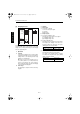
2. Signals
a. Input signals
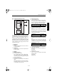
(1) PS41 (PS41 to PRCB)
Charging wire cleaning pad home position
detection signal.
This signal detects the reference position of the
charging wire cleaning pad home position.
[L]: HP detected
[H]:HP not detected
(2) PS42 (PS42 to PRCB)
Charging wire cleaning pad limit detection sig-
nal.
This signal detects the limit position of charging
wire cleaning pad.
[L]: Limit position detected
[H]:Limit position not detected
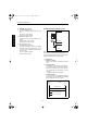
b. Output signals
(1) M23 DRIVE1, 2 (PRCB to M23)
M23 drive control signal.
The drive direction of M23 is controlled by switch-
ing the drive current directions of two signals.
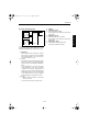
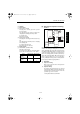
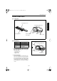
[6] M18 (Transfer/Separation Cleaning)
Control
M18 (transfer/separation cleaning) is a 24 VDC motor
which is controlled by the PRCB (printer control board)
via the ADUSDB (ADU stand drive board). Between
the PRCB and ADUSDB, signals are exchanged using
serial data. Related signals are PS11 (transfer/sepa-
ration wire cleaning pad HP) and PS12 (transfer/sep-
aration wire cleaning pad limit). When the front right or
left door of this machine opens or closes, MS1 (inter-
lock 1) or MS2 (interlock 2) operates to interrupt the DC
power supply to PRCB, stopping the M18.
1. Operation
a. Purpose of driving
M8 is used to drive the transfer and separation
wire cleaning pads.
b. Operation timing
The transfer and separation wires are cleaned
when the main switch is turned ON, when the fix-
ing temperature is lower than 50°C, or when the
specified copy count is reached.
* Changeable with 25 mode DIPSW.
Status M23 DRIVE1 M23 DRIVE2
Forward stroke of
cleaning
HL
Return stroke of
cleaning
LH
Stop
LL
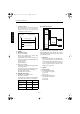
MS2 MS1
PRCB
DCPS2
PS11
5VDC
PS11
SGND
PS12
24VDC
PGND
M18
DRIVE1
M18
DRIVE2
ADUSDB
M18
DCPS1
5VDC
SGND
PS12
Di850g.book5ページ2002年7月12日 金曜日 午前8時36分