DRAFT — FOR INTERNAL USE ONLY » User Guide « CPS3003-SA Doc. ID: 1054-3213, Rev. 2.
User Guide CPS3003-SA Revision Histor y Brief Description of Changes Date of Issue 1.0 Initial issue 13-May-2014 2.0 Extensive changes 10-Feb-2014 Impr int Kontron Europe GmbH may be contacted via the following: MAILING ADDRESS TELEPHONE AND E-MAIL Kontron Europe GmbH Sudetenstraße 7 D - 87600 Kaufbeuren Germany +49 (0) 800-SALESKONTRON sales@kontron.com For further information concerning other Kontron products, please visit our Internet website: www.kontron.com.
User Guide CPS3003-SA Contents Revision History .......................................................................................................... 2 Imprint ..................................................................................................................... 2 Contents .................................................................................................................... 3 Tables ...........................................................................................
User Guide 2.7.1.2 2.7.2 2.7.3 2.7.4 2.7.5 2.7.6 2.7.7 2.7.7.1 2.7.7.2 General Purpose LEDs .................................................................................. 22 USB Interfaces ........................................................................................... 24 DisplayPort Interfaces ................................................................................. 24 Serial Ports ...............................................................................................
User Guide 7.4 7.5 7.6 7.6.1 7.6.2 7.6.3 7.6.4 7.6.5 Front Panel of the CPS3003-SA with CPS3003-BRIDGE Module ............................... 48 CPS3003-BRIDGE Module Board Layout ............................................................ 48 Module Interfaces (Front Panel and Onboard).................................................... 49 USB Interface ............................................................................................ 49 Serial Port..............................................
User Guide 12 uEFI BIOS .......................................................................................... 60 12.1 12.2 12.2.1 12.2.2 12.2.3 12.2.3.1 12.2.3.2 12.2.4 12.3 12.3.1 12.3.1.1 12.3.1.2 12.3.2 12.4 12.4.1 12.4.2 12.4.3 12.4.3.1 12.4.3.2 12.4.3.3 12.4.3.4 12.5 12.5.1 12.5.2 12.5.3 Starting the uEFI BIOS ................................................................................. 60 Setup Menus .........................................................................................
User Guide CPS3003-SA 1 2 3 4 5 6 7 8 9 10 11 12 13 14 15 16 17 18 19 20 21 22 23 24 25 26 27 28 29 30 31 32 33 34 35 36 37 38 39 40 41 42 43 44 45 46 CPS3003-SA Main Specifications ............................................................................ 15 Standards ........................................................................................................ 18 Additional Standards for Boards Ordered with Ruggedized Service ................................. 19 Related Publications ........
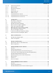
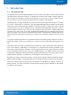
User Guide CPS3003-SA 1 2 3 4 5 6 7 8 9 10 11 12 13 14 15 16 17 18 19 20 21 22 CPS3003-SA Functional Block Diagram ................................................................... 4 HP CPS3003-SA Front Panel ............................................................................... 4 HP CPS3003-SA Board Layout (Top View) .............................................................. 4 HP CPS3003-SA Board Layout (Bottom View) .........................................................
User Guide CPS3003-SA Warranty Within the warranty period, the repair of products is free of charge as long as warranty conditions are observed. The warranty does not apply to defects resulting from improper or inadequate maintenance or handling by the buyer, unauthorized modification or misuse, operation outside of the product’s environmental specifications or improper installation or maintenance.
User Guide CPS3003-SA 1 Introduction B o a r d O ve r v i ew CompactPCI® Serial, adopted by the PICMG® consortium in 2011, describes a new base standard. The CompactPCI Serial standard introduces a completely new connector that enables a higher signal density and supports even higher transmission frequencies of up to 12 Gb/s as well as modern point-topoint connections such as PCI Express®, SATA, Ethernet and USB on the backplane.
User Guide CPS3003-SA 1. 2 S y s te m E x p a n s i o n C a p a b i l i t i e s The CPS3003-EXTIO module for the 8 HP CPS3003-SA version provides one USB 3.0 port, one COM port, and one CFast socket on the front panel. For further information on the CPS3003-EXTIO extension module, refer to Chapter 6. 1.2.2 CPS3003-BRIDGE Extension Module (9 HP) The CPS3003-BRIDGE module for the 9 HP CPS3003-SA version provides one USB 3.0 port, one COM port, and one CFast socket on the front panel.
www.kontron.com Hot Swap Handle Dual UART Power Button Func. CPLD HighSpeed I/O Extension Connector Rear I/O RTC Battery 2x USB 2.0 x1 x1 2x DP 3V optional SFF-XDP Debug TPM LPC SATA USB 3.0 PCIe USB 2.0 PCIe PCIe DP DMI SPI Boot Flashes (standard/ recovery) SPI SATA Rear I/O MAG Rear I/O Eth Onboard Power Supplies MAG Rear I/O Eth 12V Power 3.3/5V USB Power COM1-2, GPIO GbE B GbE A 1x USB 2.0 1x DisplayPort USB 2.0 DP 1x USB 3.0 / 2.0 P6 Rear I/O 5x PCIe 2.
User Guide CPS3003-SA 1.3.2 Front Panel Figure 2: 4 HP CPS3003-SA Front Panel HS DP-B HS (blue): TH (red/green): WD (green): Hot Swap Status Temperature Status Watchdog Status General Purpose LEDs TH LED3..0 (red/green/red+green): General Purpose / POST Code DP-A WD Note: If the General Purpose LEDs 3..0 are lit red during boot-up, a failure is indicated before the uEFI BIOS has started.
User Guide CPS3003-SA 1.3.3 Board Layout Figure 3: 4 HP CPS3003-SA Board Layout (Top View) J16 J7 DRAFT — FOR INTERNAL USE ONLY P6 Battery P5 J8 SATA Flash Module J10 P4 Smart Extension Module J9 Intel® Core™ i7 P3 Intel® QM77 J11A P2 J11B P1 Figure 4: 4 HP CPS3003-SA Board Layout (Bottom View) ON SW1 1234 HS LED TH LED WD LED LED0 LED1 LED2 LED3 www.kontron.
User Guide CPS3003-SA 1. 4 Te ch n i c a l S p e c i f ic a t i o n Table 1: CPS3003-SA Main Specifications CPU The CPS3003-SA suppor ts the following 3 rd generation processors: » Quad-core Intel® Core™ i7-3612QE (SV), 2.1 GHz, 6 MB L3 cache » Dual-core Intel® Core™ i7-3555LE (LV), 2.5 GHz, 4 MB L3 cache » Dual-core Intel® Core™ i7-3517UE (ULV), 1.
User Guide CPS3003-SA Table 1: CPS3003-SA Main Specifications (Continued) FEATURES Up to 13 USB por ts: » » » » » » Serial 6 x USB 2.0 on the CompactPCI Ser ial interface 2 x USB 3.0 / 2.0 on the CompactPCI Serial interface 2 x USB 2.0 ports on the front I/O 1 x USB 2.0 port on the rear I/O interface 1 x USB 3.0 / 2.0 por t on the rear I/O interface 1 x USB 3.0 / 2.
User Guide CPS3003-SA Table 1: CPS3003-SA Main Specifications (Continued) FEATURES System Status LEDs: LEDs / Switches » HS (blue): » TH (red/green): » WD (green): General Purpose LEDs: » LED3..
User Guide CPS3003-SA Table 1: CPS3003-SA Main Specifications (Continued) FEATURES SPECIFICATIONS Power Consumption See Chapter 4 for details. Temperature Range Operational: 0°C to +60°C Standard (depending on processor version and airExtended (with Intel® Core™ i7-3517UE, 1.7 GHz ULV -40°C to +85°C Without hard disk and without battery processor only) Storage: 3.
User Guide CPS3003-SA In addition, boards ordered with the ruggedized service comply with the following standards as well.