® Superior Liquid Cooling Systems Exos-2 LX, Exos-2.5 User’s Manual English v1.2 Protected by U.S. Patents 6,313,990; 6,664,627; 7,167,366; 7,295,436 Other Technology Pending U.S.
This User Manual is updated regularly. Please be sure to check our support page for a newer version of this guide: www.koolance.com/support GENERAL PRECAUTION Please read this manual carefully before beginning the installation of your Koolance system. This manual assumes the user has basic experience in building and configuring computer systems. Information referring to traditional hardware assembly is intentionally brief.
! ! ! WARNING: The Koolance liquid & coolant pack contain chemicals which may be harmful or fatal if swallowed. KEEP THIS AND ALL DANGEROUS CHEMICALS OUT OF THE REACH OF CHILDREN. If ingestion has occurred, seek medical attention immediately. Give two glasses of water. Do not induce vomiting. In the case of eye contact, flush eyes immediately with water for 15 minutes. Remove contact lenses. Call a physician if irritation persists.
Table of Contents Introduction 1 Exos System Diagram .................................................................................... 4 LED Display Panel .......................................................................................... 5 Connecting Exos Systems 7 Positioning the Exos ....................................................................................... 8 External Nozzles & Power Cable ....................................................................
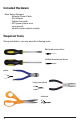
Included Hardware Exos Series Systems: - External Power Cable - Slot Adapter - Rubber foot pads - ATX power jumper wire - user manual - shutoff nozzles (select models) Required Tools During installation, you may need the following tools: flat-head screw driver phillips-head screw driver pliers long-nose pliers scissors iv
1 Chapter Introduction User Manual 1
Congratulations on your purchase of a Koolance system! As the most sophisticated product of its kind, Koolance offers many unique features found nowhere else in the realm of computer cooling. In addition, you can expect to enjoy all of the advantages that water-cooling technology brings with it. Advantages of Water Cooling Water transfers 30 times faster, and holds over 4 times more heat than air.
The heart of a liquid cooling system is the pump. This device pushes liquid through each cooler and into the heat exchanger. Koolance systems use dual pumps to increase reliability and liquid pressure. If one pump should fail, the second can help prevent potential damage caused by heat increase. Every Koolance system includes built-in hardware safety features.
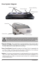
Exos System Diagram Radiator Cooling Fans Reservoir & Pump Reservoir Refill Plug LED Display Panel Coolant Inlet Coolant Outlet ! Power Connection CAUTION: (Pump speed control models) Due to electrical tolerances, the lowest pump speed settings may stop the pump from running. Be sure the pump continues to run when operated at lower speeds. Reservoir & Pumps - The coolant tank is grouped with the main pump(s) and is primarily responsible for bleeding air from the liquid while the system is operating.
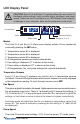
LED Display Panel ! CAUTION: Exos-2 LX and Exos-2.5 systems allow full user control of hardware safety settings, such as audio alarm, shutdown, and pump speed. Please be sure to configure your LED Display Panel properly, or damage to your computer, data, and/or equipment could result. Increase Setting Current Mode Value Decrease Setting Mode Select Display in ºC or ºF Modes The Exos-2 LX and Exos-2.5 offers seven display options. All are reached by continually pressing the SET button: 1.
the ▼ or ▲ buttons to adjust pump settings, or hold down an arrow to skip to the lowest or highest mode directly. There is no automatic mode available for the pump setting.
2 Chapter Connecting Exos Systems User Manual 7
Positioning the Exos The Exos is designed to operate in various locations, but it must run upright. Air filtration is not possible in all orientations. If the Exos can not be placed adjacent to the computer, it can be moved farther away. Depending on heat load, 3-6 feet (12 meters) should be an acceptable distance for most Exos configurations. Extra tubing can be purchased from Koolance.com or your local reseller. Rubber foot pads are included to place the Exos on or near your computer chassis.
External Nozzles & Power Cable Cut the included 10mm (3/8”) tubing into two segments. You will need to connect each to the Exos’ rear nozzles. Each tubing connection uses a threaded compression fitting (“hose screw”) to keep it secure. To connect these components, first thread a hose screw onto the tube end. Squeeze the tube while pushing it firmly over the nozzle. Tubing should completely cover the nozzle.
Connecting the Slot Adapter The Slot Adapter allows the Exos to connect with any ATX computer through an available card slot. It is responsible for both input and output tubes, along with the external power cable connection. This prevents the computer chassis from requiring any modifications for the cooling unit.
Installing the Slot Adapter Install the Slot Adapter into any available rear card slot in your computer. Screw the Slot Adapter in place as you would a normal device. From the rear of the case, carefully feed both ends of the liquid tubing through the Slot Adapter and into the chassis. Plug the other end of the Exos’ external power cable into the Slot Adapter.
Power Connection The Exos-2 LX and Exos-2.5 requires approximately 20-30W from any standard ATX power supply. Since it is adapted internally, it does not need a dedicated external AC power cable. Connect the Slot Adapter’s main power plug (12 Volt 4-pin Molex) to the computer’s power supply. Without this important connection, the Exos will NOT operate. ! 12 CAUTION: The Power Connection is vital to system operation.
ATX Power Switch The ATX “pass through” lead is responsible for shutting off your computer if sensor channel #1 reaches 3ºC (5ºF) above the preset alarm temperature (See LED Display for alarm configuration). Connect the male ATX power lead from the Slot Adapter to the chassis main power button. To Motherboard To ATX Power Button Connect the female ATX power lead from the Slot Adapter to the motherboard’s power switch connection (often marked “PWRSW”, “PWSW”, or “PWBT”).
Cooler & Tubing Configuration Depending on the cooling blocks (“coolers”) in your Koolance system and nozzle sizes (1/4”, 3/8”, etc.), they may be connected in series, parallel, or a mixture of both for best performance. Recommended configurations are illustrated below. If you are comfortable experimenting with different tubing setups, there may be more optimal configurations for your particular system. NOTE: For simplicity, tubing ID (internal diameter) will be listed in metric units.
Parallel Systems Koolance coolers which are 6mm (1/4”) can still be effectively used in Exos series systems. Using a parallel tubing configuration with hose splitters will help maintain coolant flow rate through these systems. 10 6 10 6 GPU Block CPU Block 6 10 10 10 CPU 1 Block 10 CPU 2 Block NB Block 10 6 SB Block 6 6 6 6 6 HD 2 Block HD 1 Block 6 The maximum number of coolers allowed in a system will depend upon your specific thermal requirements and hose configuration.
Disconnecting Hoses Nozzles are designed to attach tightly. If you need to remove a hose for any reason, it may not pull off easily, even after unscrewing the compression fitting. Usually, a connection will come free by squeezing the hose on top of the nozzle and pulling away. If this fails, cutting a small incision lengthwise (parallel) along the nozzle should free it. When a hose screw has been removed, it may have distorted the tubing beneath it.
Hose Lengths Before installing your liquid coolers, appropriate lengths of tubing must be cut to connect each device. It is generally easier to estimate the required tubing amounts with installed computer hardware. On the rear of the Exos, the nozzle to the left is the outlet of the radiator. The right nozzle is the inlet. Generally, the outlet will connect first with your CPU Cooler.
Continue connecting all of your coolers in the system until there are no longer any open tube ends. Liquid Coolers You should now install the liquid coolers (CPU, GPU, Hard Drive, etc.) to your hardware before continuing this User Manual. Please refer to your cooler kit’s individual installation instructions, then continue on to the next section.
3 Chapter Filling & Maintenance ! WARNING: The Exos-2 LX and Exos-2.5’s powerful single pump can not be run “dry” for any period of time. Never power-on the computer or cooling system without sufficient liquid in the reservoir. Dry-running (and thereby damaging the pump) is not covered under the Koolance product warranty.
Testing & Filling Once all of the coolers have been connected, the system can be filled with coolant. The refill plug is located on top of the reservoir. Remove the large slot-headed screw (with a screwdriver or large coin). To avoid damaging the tank threading, never overtighten the metal refill plug when screwing it back in. ! WARNING: The liquid coolant is electrically conductive. Use caution when filling the system, and keep all liquids away from computer hardware and power cables.
! CAUTION: When filling, the Exos must be higher than all internal water blocks or liquid will exit the fill port. Replace the refill plug screw. The cooling system can be “jump-started” to assist in the circulation process without booting-up the computer. This will also allow you to check your hose connections and make sure there are no folds or blockages in the tubing. ! CAUTION: Jumping the incorrect ATX power supply pins can cause permanent damage to the power supply.
Adding Coolers & Maintenance Under normal circumstances, the liquid coolant does not require replacement. However, if it becomes contaminated, unclear, or significantly changes color, it must be replaced. A Koolance “drain valve” (sold separately) is recommended to make that process easier. If you are upgrading or removing a cooling block in your system, please follow the instructions below. ! CAUTION: Any time a hose is disconnected with coolant still inside, leaking can occur.
Troubleshooting We hope your Koolance system will provide you with years of reliable cooling performance. To help avoid unnecessary RMA issues, we have prepared this list of possible operational problems, and their most common solutions. 1. The pumps do not appear to be operating properly... The pumps need to be “burped” during the initial bleeding process to avoid this situation. Reduce pump speed (but not low enough to stop the pumps).
be malfunctioning. Please visit our support web page for more information. Verify that the pump is operating (see Troubleshooting #1), and that liquid flow is present in the reservoir. Note that if the reservoir was over-filled during system assembly, this procedure is not possible since there will be no visible air gap. 5. My system has boot-up problems, or does not turn on... The majority of these problems are not related to the Koolance case, but hardware or configuration issues.
8. The LED Display Panel shows 5 - 0 or 5 - 5... 5 - 0 (“S - O”): Sensor open.This indicates a temperature sensor can not be detected for a given channel. If there is no sensor connected to a channel, this is its normal status. 5 - 5 (“S - S”): Sensor short. This indicates that the sensor may be faulty or electrically bypassed. If the sensor is listed with an “S-S” status, the cooling system alarm will sound. The sensor will need to be replaced. Please visit our support web page.
Limited Warranty Koolance Incorporated (“Koolance”) warrants each new Koolance liquid-cooled system (“the system”), against defects in materials or workmanship for a period of one year from the date of purchase, and agrees to repair or replace any defective Koolance system without charge. Shipping costs are non-refundable. This warranty is non-transferable. All warranty claims must be accompanied by the original proof of purchase.
www.koolance.