® Superior Liquid Cooling Systems www.koolance.com PC4-1000 & RP-1000 Based Systems User’s Manual English v1.02 ISO 9001 Protected by U.S. Patents 6,664,627; 6,313,990; 6,234,240; 5,731,954 Other Technology Pending U.S.
This User Manual is updated regularly. Please be sure to check our support page for a newer version of this guide: www.koolance.com/support GENERAL PRECAUTION Please read this manual carefully before beginning the installation of your Koolance system. This manual assumes the user has basic experience in building and configuring computer systems. Information referring to traditional hardware assembly is intentionally brief.
! ! ! WARNING: The Koolance liquid & coolant pack contain chemicals which may be harmful or fatal if swallowed. KEEP THIS AND ALL DANGEROUS CHEMICALS OUT OF THE REACH OF CHILDREN. If ingestion has occurred, seek medical attention immediately. Give two glasses of water. Do not induce vomiting. In the case of eye contact, flush eyes immediately with water for 15 minutes. Remove contact lenses. Call a physician if irritation persists.
Table of Contents Introduction 1 Component Diagram ....................................................................................... 4 LED Display Panel .......................................................................................... 5 Connecting PC4-1000 Systems 7 Reservoir & Pump Connections ...................................................................... 8 Power Connection ...........................................................................................
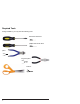
Required Tools During installation, you may need the following tools: flat-head screw driver phillips-head screw driver pliers long-nose pliers scissors iv
1 Chapter Introduction User Manual 1
Congratulations on your purchase of a Koolance system! As the most sophisticated product of its kind, Koolance offers many unique features found nowhere else in the realm of computer cooling. In addition, you can expect to enjoy all of the advantages that water-cooling technology brings with it. Advantages of Water Cooling Water transfers 30 times faster, and holds over 4 times more heat than air.
Every Koolance system includes built-in hardware safety features. Our proprietary power control board constantly monitors liquid temperature, sounding an alarm if it should get too high, and even turning-off your computer if you are not there to do so. But Koolance’s innovations extend beyond just cooling features. Our safe, patent-pending CPU Retention Clip places even pressure across the CPU, protecting the chip and simplifying installation.
Component Diagram Heat Exchanger and Fan Unit Radiator Cooling Fans Underneath: Radiator (Primary Heat Exchanger) Pump and Reservoir Unit Pump Nozzle Sockets Power Circuit Board LED Display Reservoir Radiator - The primary heat exchanger is located beneath the fan cooling module. This is the main cooling element, and provides high thermal dissipation in a relatively small area. Inside, an aluminum mesh (louver fin) is webbed between horizontal liquid paths.
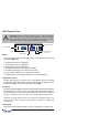
LED Display Panel ! CAUTION: PC4/RP-1000 systems allow full user control of hardware safety settings, such as audio alarm, shutdown, and pump speed. Please be sure to configure your LED Display Panel properly, or damage to your computer, data, and/or equipment could result. Increase Setting Current Mode Value Decrease Setting Mode Select Display in ºC or ºF Modes The PC4/RP-1000 offers seven display options. All are reached by continually pressing the SET button: 1.
the ▼ or ▲ buttons to adjust pump settings, or hold down an arrow to skip to the lowest or highest mode directly. There is no automatic mode available for the pump setting.
2 Chapter Connecting PC4-1000 Systems User Manual 7
Reservoir & Pump Connections The radiator fans, temperature sensors, and ATX pass-through wire should already be connected to your reservoir unit. If not, please connect them where indicated below. Also insert your desired Koolance inlet and outlet G 1/4 threaded nozzles.
! CAUTION: The Power Connection is vital to system operation. A 12V 4-pin plug from the power supply must remain connected to the cooling system at all times while the computer is in use. ATX Power Switch The ATX “pass through” lead is responsible for shutting off your computer if any temperature sensor reaches 3ºC (5ºF) above the preset alarm temperature (See LED Display for alarm configuration). Connect the male ATX power lead from the PC4-1000 to the chassis main power switch.
Cooler & Tubing Configuration Depending on the cooling blocks (“coolers”) in your Koolance system and nozzle sizes (1/4”, 3/8”, etc.), they may be connected in series, parallel, or a mixture of both for best performance. Recommended configurations are illustrated below. If you are comfortable experimenting with different tubing setups, there may be more optimal configurations for your particular system. NOTE: For simplicity, tubing ID (internal diameter) will be listed in metric units.
Parallel Systems Koolance coolers which are 6mm (1/4”) can still be effectively used in Exos-2 series systems. Using a parallel tubing configuration with hose splitters will help maintain coolant flow rate through these systems. 10 6 10 6 GPU Block CPU Block 6 10 10 10 CPU 1 Block 10 CPU 2 Block NB Block 10 6 SB Block 6 6 6 6 6 HD 2 Block HD 1 Block 6 The maximum number of coolers allowed in a system will depend upon your specific thermal requirements and hose configuration.
Connecting Hoses Each tubing connection uses a threaded compression fitting (“hose screw”) to keep it secure. To connect these components: Thread a hose screw onto the tube end. Squeeze the tube while pushing it firmly over the nozzle. Tubing should completely cover the nozzle. Tighten the connection by sliding the compression fitting down over the nozzle and screwing it securely by hand. Do not overtighten the nozzle fitting.
Disconnecting Hoses Hoses are designed to snug firmly around the nozzle. If you need to remove a hose for any reason, it may not pull off easily, even after unscrewing the compression fitting. Usually, a connection will come free by squeezing the hose on top of the nozzle and pulling away. Pulling in front of the nozzle will stretch the tubing and make it tighter. If this fails, cutting a small incision lengthwise (parallel) along the nozzle will free it.
Tubing The Radiator & Reservoir Nozzles and tubing must be installed onto both the Radiator and Reservoir/Pump unit. To reach the Radiator nozzle sockets, it is generally easiest to remove the top assembly via its 8 screws. Then, push up gently on the radiator to access the nozzle sockets. Be careful not to damage the radiator fins. The radiator can be installed with either its nozzles facing: 1) the front or chassis, or 2) the back of the chassis. Each has stipulations.
Firmly screw tighten the desired nozzles to the Radiator and Reservoir. (See “Connecting Hoses” for further details.) Next, connect tubing from either nozzle of the Radiator to the “Outlet” of the Reservoir/Pump. (The Radiator does not have a coolant flow orientation.) NOTE: Make sure to leave enough tubing between the Radiator and Reservoir/Pump Unit so it can be pulled out a little for filling. (Please see “Filling and Maintenance” for further details.
Hose Lengths Before installing your liquid coolers, appropriate lengths of tubing must be cut to connect each device. It may be easier to temporarily lay your motherboard and video card inside the case to better-estimate the required amounts. Generally, the outlet of the radiator will connect with your CPU Cooler, but this is completely optional. The reservoir and pump unit may be located before or after the radiator, depending on the preferred arrangement of water blocks.
Continue connecting all of your coolers in the system until there are no longer any open tube ends. Liquid Coolers You should now install the liquid coolers (CPU, GPU, Hard Drive, etc.) to your hardware before continuing this User Manual. Please refer to your cooler kits’ individual installation instructions, then continue on to the next section. For temperature probe placement of sensor #1, please refer to the installation sheet included with your Koolance CPU Cooler.
3 Chapter Filling & Maintenance ! 18 WARNING: The RP-1000’s powerful single pump can not be run “dry” for any period of time. Never power-on the computer or cooling system without sufficient liquid in the reservoir. Dry-running (and thereby damaging the pump) is not covered under the Koolance product warranty.
Testing & Filling Once all of the coolers have been connected, the system can be filled with coolant. The refill plug is located on top of the reservoir bay unit. Free this component by removing its side drive screws. Slowly pull it out just enough to expose the refill plug (about 2.75”, 7cm). Depending on your chassis design, you may need to hold the bay unit with one hand to support it during the filling process. Unscrew the small metal refill plug by hand.
Do not overfill the reservoir. It is recommended to keep paper towels on hand just in case. The liquid coolant should be filled up to about 6mm (1/4”) from the reservoir’s top. This small gap will catch air as it circulates through the system. Replace the refill plug, slide the reservoir unit back into the drive bay, and mount it using the side screws. The cooling system can be “jump-started” to assist in the circulation process without booting-up the computer.
Adding Coolers & Maintenance Under normal circumstances, the liquid coolant does not require replacement. However, if it becomes contaminated, unclear, or significantly changes color, it must be replaced. A Koolance “drain valve” (sold separately) is recommended to make that process easier. If you are upgrading or removing a cooling block in your system, please follow the instructions below. ! CAUTION: Any time a hose is disconnected with coolant still inside, leaking can occur.
Troubleshooting We hope your Koolance system will provide you with years of reliable cooling performance. To help avoid unnecessary RMA issues, we have prepared this list of possible operational problems, and their most common solutions. 1. The pumps do not appear to be operating properly... The pumps need to be “burped” during the initial bleeding process to avoid this situation. Reduce pump speed (but not low enough to stop the pumps).
be malfunctioning. Please visit our support web page for more information. Verify that the pump is operating (see Troubleshooting #1), and that liquid flow is present in the reservoir. Note that if the reservoir was over-filled during system assembly, this procedure is not possible since there will be no visible air gap. 5. My system has boot-up problems, or does not turn on... The majority of these problems are not related to the Koolance case, but hardware or configuration issues.
8. The LED Display Panel shows 5 - 0 or 5 - 5... 5 - 0 (“S - O”): Sensor open.This indicates a temperature sensor can not be detected for a given channel. If there is no sensor connected to a channel, this is its normal status. 5 - 5 (“S - S”): Sensor short. This indicates that the sensor may be faulty or electrically bypassed. If the sensor is listed with an “S-S” status, the cooling system alarm will sound. The sensor will need to be replaced. Please visit our support web page.
Limited Warranty Koolance Incorporated (“Koolance”) warrants each new Koolance liquid-cooled system (“the system”), against defects in materials or workmanship for a period of one year from the date of purchase, and agrees to repair or replace any defective Koolance system without charge. Shipping costs are non-refundable. This warranty is non-transferable. All warranty claims must be accompanied by the original proof of purchase.