Parameter Guide E 2
About this manual Parameters in the LCD display screen “ ” Parameters displayed in the LCD screen are enclosed in double quotation marks “ ”. This “Parameter Guide” contains explanations and other information regarding the operations of the parameters and settings on the X50/microX. The explanations are organized by mode, page, and tab. Explanations and other information on the effects and their parameters are also provided for each effect.
Table of Contents 6–4: Lvl/Pan (Amp2 Level/Pan) ......................25 6–5: Mod. (Amp2 Modulation)..........................25 6–6: EG (Amp2 EG) ................................25 1. Program mode........................... 1 PROG PAGE MENU .................................... 1 PROG 7: Ed–Arp/Ctrls (Arpeggiator/ Controls).................................................. 25 7–1: Setup (Arpeg. Setup)...................................25 PROG 0: Play..............................................
COMBI 4: Ed–MIDI Filter2 ....................... 44 1–2: TA1..16 (Tone Adjust1) .............................. 59 4–1: MIDI 2–1 (MIDI Filter 2–1) ........................ 44 1–3: TA2..8 (Tone Adjust2) ................................ 59 4–2: MIDI 2–2 (MIDI Filter 2–2) ........................ 44 1–4: TA2..16 (Tone Adjust2) .............................. 59 X50: 4–3: MIDI 2–3 (MIDI Filter2–3) ................. 44 1–5: TA3..8 (Tone Adjust3) ................................
6–5: Review .......................................................... 68 MULTI 7: Arp/Ctrls (Arpeggiator/Controls).......................... 69 GLOBAL 5: Arp.Pattern........................... 89 5–1: Setup..............................................................89 5–2: Edit ................................................................91 7–1: Set..8 (Setup T01–08)................................... 69 microX: GLOBAL 6: Ext. Control ............. 93 7–2: Set..16 (Setup T09–16)..................
10: St.Rndm Filter (Stereo Random Filter)..... 109 45: St.MltTap Dly (Stereo Multitap Delay) ... 129 11: St.Exct/Enhcr (Stereo Exciter/Enhancer) ......................... 110 46: St.Mod. Delay (Stereo Modulation Delay) ........................ 130 12: St.Sub OSC (Stereo Sub Oscillator)........... 110 47: St.DynamicDly (Stereo Dynamic Delay)............................. 130 13: Talking Mod (Talking Modulator) ........... 111 14: St.Decimator (Stereo Decimator) .............. 112 15: St.
7: Exct–Phaser (Exciter – Phaser).................. 143 7. Appendices ............................ 151 78: Exct–M.Dly (Exciter – Multitap Delay) ... 143 79: OD/HG–AmpSim (Overdrive/Hi.Gain – Amp Simulation).... 144 Alternate Modulation Source (AMS) ........ 151 80: OD/HG–Cho/Fl (Overdrive/Hi.Gain – Chorus/Flanger) .... 144 About Alternate Modulation Sources ............151 About Alternate Modulation ...........................151 AMS (Alternate Modulation Source) List .............
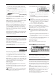
Use the following procedure to select the desired page from within the current mode. In this display page you can select and play programs. 2 All MIDI data in PROG 0: Play is transmitted and received on the Global MIDI Channel (☞GLOBAL 1– 1a). 3 1 Press the [MENU/OK] button to access the “PAGE MENU.” The “PAGE MENU” will show an abbreviated name for each page. 0 PROG 0: Play 1 PROG PAGE MENU PROG 1. Program mode 4 0–1: Program 6 2 Use the ClickPoint [√][®][π][†] to select a page.
microX: Use the PROGRAM [A]–[GM] buttons to select the bank. The microX provides rewritable banks A, B, C, D, and E, each containing 128 programs (total 640). As for nonrewritable program areas, it provides banks G (capital programs for GM), and bank g(d) (drums). If you press a PROGRAM [A]–[GM] button, you will automatically enter Program mode even if you had been in a different mode.
PROG The ten’s place of the program number will be fixed. 1 Select “Write Program” to access the dialog box. 2 Now you can press a numeric button [0]–[9] to enter the one’s place in a single action. 3 In “Category,” specify the category of the program that you are writing. The category selected here can be used to find this program when selecting a program in Program, Combination, Multi.
Editing done using the Performance Editor will occur within the range of the corresponding parameter. If after using the Performance Editor to modify a value, you move to another page or mode and then return, the sound will remain in its edited state but the value shown in the LCD screen by the Performance Editor will be +00. You may do further editing from this state if you wish.
External control lets you use the REALTIME CONTROLS knobs to control an external MIDI device. You can assign a MIDI control change and MIDI channel to each of the four knobs, and switch between three such settings (A, B, C) to control your external device. One set lets you transmit a total of twelve (4 × 3) different MIDI control changes. These are called “external control sets,” and you can choose from 64 such sets. Make settings for the program arpeggiator (☞“PROG: Ed– Arp/Ctrls”).
PROG 1: Ed–Basic On (checked): When the same note is played repeatedly, the previous note will be silenced before the next note is sounded, so that the notes do not overlap. Here you can make basic settings for the oscillator(s). Legato [Off, On] This is available when the “Mode (Voice Assign Mode)” setting is set to Mono.
User Octave 00–15: These are the single-octave scales that are specified in “User Octave Scale” (GLOBAL 2–1a). The multisample(s) (waveform) or drum kit on which the program will be based can be selected here for oscillator 1 and/or oscillator 2. You can use the following multisamples. As this value is increased, a greater variance will be applied to the pitch when each note is sounded. Normally you will set this to 0.
On (checked): The sound will start from the start offset location that is pre-determined for each multisample. Off (unchecked): The sound will start from the beginning of the multisample waveform. Rev (High Reverse) [Off, On] The multisample will be played in reverse. If the multisample was originally set to reverse, it will playback without change. On (checked): The multisample will playback in reverse. Off (unchecked): The multisample will playback normally. Level (High Level) [000...
PROG 1–5: Audition Selects multisamples by category. For the procedure, refer to “Select by Category” (☞p.2). When selecting preloaded programs, you can play back a pre-specified riff (phrase) that is suitable for the sound of that program. This is called the Audition function. When you press the [AUDITION] button to turn it on, the audition riff will play back repeatedly. 0 Select by Category 1 Here you can select the audition riff and specify the transposition.
PROG 2: Ed–Pitch Here you can make pitch modulation settings for oscillators 1 and 2. X50: PBend + [–60…+12] Specifies the amount of pitch change (in semitones) that will occur when you move the [PITCH] wheel up from the center position. 2–1: OSC1 Specifies how the key position (on the keyboard) will affect the pitch of oscillator 1, and selects the controller that will modify the pitch and the depth of this effect.
For example, if you set “AMS (Pitch EG AMS)” to Velocity and set this value to +12.00, the velocity will control the range of pitch change produced by the pitch EG in a range of ±1 octave (☞p.154). As you play more softly, the pitch change will draw closer to the pitch EG levels. Pitch change (level) Note-on Note-on PROG 2–2a microX Note-on Note-off Note-off 4 Note-off X50 0 [–12.00…+12.00] Specifies the depth and direction of the effect that “AMS (Pitch EG AMS)” will have.
Intensity (AMS Intensity) [–12.00…+12.00] Specifies the depth and direction of the effect that “AMS (LFO1 AMS)” will have. With a setting of 0, modulation will not be applied. With a setting of 12.00, the OSC1 LFO1 will apply a maximum of ±1 octave of pitch modulation. Negative (–) settings will invert the LFO waveform.
X50: For example if “AMS1 (Level Mod. AMS1)” is set to SW1 #80 and 7–3b: SW1/2 Assign “SW1” is set to SW1 Mod. (CC#80), turning [SW1] on will change the Pitch EG “Level.” Increasing the absolute value of “I (AMS1 Intensity)” will produce a greater change in the pitch EG level when [SW1] is turned on. The direction of the change is specified by “S (AMS1 SW Start)” and “A (AMS1 SW Attack).” If [SW1] is off, the levels specified by the pitch EG settings will be used. microX: For example if “AMS1 (Level Mod.
PROG 3: Ed–LFOs Key Sync. Here you can make settings for the LFO that can be used to cyclically modulate the Pitch, Filter, and Amp of oscillators 1 and 2. There are two LFO units for each oscillator. By setting the LFO1 or LFO2 Intensity to a negative (–) value for Pitch, Filter, or Amp, you can invert the LFO waveform. [Off, On] On (checked): Key Sync. will be On. The LFO will start each time you play a note, and an independent LFO will operate for each note. Off (unchecked): Key Sync.
Int (AMS2 Intensity) [–99…+99] Indicates settings for a second alternate modulation source that will adjust the frequency of the oscillator 1 LFO1. PROG 3–2: 1 LFO2 (OSC1 LFO2) Here you can make settings for the OSC1 LFO2, which is the second LFO that can be applied to oscillator 1. (☞“3–1: OS1LFO1 (OSC1 LFO1)”) However, it is not possible to use the LFO to apply modulation in “AMS1 (Freq. AMS1)” or “AMS2 (Freq. AMS2)” of Freq. Mod. 0 AMS2 (Freq.
PROG 4: Ed–Filter1 Reso.AMS (Resonance AMS) [Off, (PEG, FEG, AEG, LFO, KT, EXT)] Indicates settings for filter 1, which controls the tone of oscillator 1. You can select either a 24 dB/oct low pass filter with resonance, or a 12 dB/oct low pass filter and 12 dB/oct high pass filter connected in series. When “Mode (Oscillator Mode)” (1–1a) is Single, Drums you can use filter 1. When it is Double, you can use filters 1 and 2. In the case of Single and Drums, the filter 2 pages cannot be selected.
Key: Specifies the note numbers at which keyboard tracking will begin to be applied, and set the “Int. to A” and “(Int. to) B” parameters to specify the depth and direction of the change applied to filter 1 A and B. For the range of notes between “Low (KBDTrk Key Low)” and “High (KBDTrk Key High),” the cutoff frequency will change according to the key location (pitch). X50: You can also input a value by playing a note on the keyboard while you hold down the [ENTER] button.
This value is added to the setting of the Filter A “Frequency (A Frequency)”(4–1b). 4–2c: AMS, Into to A, Int to B AMS (Filter EG AMS) [Off, (EXT)] Indicates the source that will control the depth and direction of the effect that the time-varying changes produced by the filter 1 EG will have on the cutoff frequency of filters 1A and 1B (☞p.152 “AMS List”). Int. to A (AMS Int.
microX: By moving the joystick in the –Y direction (down), you can control the depth at which OSC1 LFO1 modulates the cutoff frequency of filter 1B. This parameter specifies the depth and direction of the control. (☞“JS –Y Int. to A (LFO1 JS–Y Int.
S (Slope Time) [00…99] Specifies the time over which the level will change after the decay time has elapsed until the sustain level is reached. R (Release Time) [00…99] Specifies the time over which the level will change after note-on occurs until the release level is reached. 4–5c: Time Mod. (Time Modulation) These settings let you use alternate modulation to control the “T (Time parameters)” of the filter 1 EG. AMS1 (Time Mod. AMS1) 4–5b: Level Mod.
■ 4–5: UTILITY PROG 0 Here you can make settings for amp 1 which controls the volume of oscillator 1, and amp 2 which controls the volume of oscillator 2. You can also specify the panning of each oscillator. 1 These parameters are the settings for “AMS2” to control the “Time” parameters of the filter 1 EG (☞“AMS1 (Time Moc. AMS1)”–“R (AMS1 SW Release)”).
Low (KBDTrk Ramp Low) 6–1c: AMS, Intensity [–99…+99] AMS (Pan AMS) [Off, (PEG, FEG, AEG, LFO, KT, EXT)] With positive (+) values of this parameter, the volume will increase as you play notes below the “Low (KBDTrk Key Low)” note number. With negative (–) values, the volume will decrease. Indicates the source that will modify pan (☞p.152 “AMS List”). This change will be relative to the “Pan (Amp1 Pan)” setting.
Int. (AMS Intensity) [–99…+99] Specifies the depth and direction of the effect that “OSC1 LFO1” will have on the volume of oscillator 1. Negative (–) values will invert the LFO waveform. AMS (LFO2 AMS) [Off, (PEG, FEG, AEG, KT, EXT)] Indicates the source that will control the depth by which “OSC1 LFO2” (3–2) will modulate the volume of oscillator 1 (☞p.152 “AMS List”). Int.
value will cause the amp 1 EG volume levels to increase as you play more strongly. Setting “Intensity” to a negative (–) values will cause the amp 1 EG volume levels to decrease as you play more strongly. With a setting of 0, the levels will be as specified in “Amp 1 EG” (6–3a). S (AMS SW Start) [–, 0, +] Specifies the direction in which “AMS (Level Mod. AMS)” will change “S (Start Level).
PROG ■ 6–3: UTILITY PROG 7: Ed–Arp/Ctrls (Arpeggiator/Controls) X50: The B-mode functions of REALTIME CONTROLS [1]– Sync Both EGs microX: The B-mode functions of REALTIME CONTROLS The amp 1 EG and the amp 2 EG can be edited simultaneously. (Editing either one will cause the other to change.) Choose “Sync Both EGs” from the utility menu, and press the center of the ClickPoint; a check mark will appear at the left of “Sync Both EGs.” (☞4–5: UTILITY ) [1]–[4] knobs.
Octave* [1, 2, 3, 4] Specifies the number of octaves in which the arpeggio will be played. If a user arpeggio pattern is selected, the range of the arpeggio will depend on the “Octave Motion” (GLOBAL 5–1c) setting. Reso (Resolution)* [ , , , , , ] Specifies the timing resolution of the arpeggio. The notes of the arpeggio will be played at the interval you specify: , , , , , or . The speed of the arpeggio pattern is determined by the “ (Tempo)” and the “Resolution.
PROG 7–2: Zone (Scan Zone) 7–3a: Knob B Assign 1 7–2a 0 Here you can assign functions (mainly various types of control change) to the B-mode of the REALTIME CONTROLS knobs [1]–[4] (☞p.162 “Realtime Control Knobs B Assign List”). The functions you set here will take effect when you operate the REALTIME CONTROLS knobs [1]–[4] in B-mode. Knob1–B (Knob1–B Assign) 2 [Off...MIDI CC#95] 7–2a: Scan Zone Knob2–B (Knob2–B Assign) Zone Map 3 [Off...MIDI CC#95] This shows the “Scan Zone” setting.
PROG 8: Ed–InsertFX ☞For details on insertion effect, refer to p.97 “6. Effect Guide.” CC#93 will control the Send 1 level for OSC 1 and 2, and control change #91 will control the Send 2 level for OSC 1 and 2. These are controlled on the global MIDI channel “MIDI Channel” (GLOBAL 1–1a). The actual send level is determined by summing these values with the send level setting of each oscillator.
PROG 8–2b: Routing This displays the status of the insert effect. 1 5 To execute the Copy Insert Effect command, press the [MENU/OK] button. To cancel, press the [EXIT/CANCEL] button. Control change CC#93 will control the Send 1 level, and control change CC#91 will control the Send 2 level. These messages are received on the global MIDI channel specified by “MIDI Channel” (GLOBAL 1–1a).
PROG 9: Ed–MasterFX ☞For details on master effects, refer to p.97 “6. Effect Guide.” Direction (Chain Direction) [MFX1→MFX2, MFX2→MFX1] Specifies the direction of the connection when MFX1 and MFX2 are chained. MFX1→MFX2: Connect from MFX1 to MFX2. MFX2→MFX1: Connect from MFX2 to MFX1. 9–1: Setup Signal (Chain Signal) [L/R Mix, L Only, R Only] Here you can select the master effect types, switch them on/ off, specify chain order, and set the master EQ.
PROG 9–2: MFX 1 (Master Effect1) 9–3: MFX 2 (Master Effect2) Indicates effect parameter settings for the MFX1 and 2 effects that were selected in the Setup page (☞p.104–). 0 3 Select the effect that you wish to copy. If you select MFX 1 or 2, “Rtn (Return)” (return level) will be copied at the same time. If you select Master EQ, only the master EQ settings will be copied. You can also copy from an insert effect. If you check “All,” all settings of the master effects and master EQ will be copied.
32
COMBI PAGE MENU COMBI 0: Play For details on how to select pages in Combination mode, refer to p.1. In this display page you can select and play Combinations. A Combi allows you to use up to 8 programs at one time. COMBI 2. Combination mode 0 0–1: Combi (Combination) MIDI Filter 1 3: Ed–MIDI Filter1 MIDI message transmission/reception filter settings for each timbre, such as Prog Change, JS, Ribbon and After Touch. (☞p.
• Press the center of the ClickPoint to highlight the field, then use [π][†] to select a program, and press the center to finalize your selection. • 10’s HOLD (☞p.34) • Use COMBI BANK [A]–[C] to select a bank (☞p.33) • Use “Cat. HOLD” to select by category (☞p.34) • Use “Select by Category” to select by category (☞p.34) • Use the foot switch (☞p.80, 164) • Receive a MIDI program change (☞p.171) microX: • Turn the [VALUE] dial.
Select by Category Selects a combination by category. For the procedure, refer to “Select by Category” (☞p.2) X50 • Press the center of the ClickPoint to highlight the field in the display, use [π][†] to make your choice, and press the center to confirm. • Use PROG BANK [A]–[GM] to select a bank (☞p.1) • Receive a MIDI program change to select a program (☞p.171) COMBI microX: 0–2c 0–2d 0–2a: Bank, Combi Select, Cat.
0–2d: Selected Timbre Information This shows information on the timbre (1–8) that is currently selected for editing. OSC1 Left OSC2 Center OSC1: Amp1 Pan=L001 OSC2: Amp2 Pan=R127 Timbre No.: Bank No., Prog No.: and name This shows the timbre number, and the program bank, number and name selected for that timbre.
To save the edits you make, use “Write Combination.” The arpeggiator can also be edited in realtime by the REALTIME CONTROLS C-mode [TEMPO] knob, [ARP-GATE] knob, [ARP-LENGTH] knob, and [ARP-VELOCITY] knob. (☞OG p.91) COMBI ☞“Write Combination,” “Solo Selected Timbre,” “Select by Category” (0–1) microX: 0–6: Ext. Control 2 1 0 External control lets you use the REALTIME CONTROLS knobs to control an external MIDI device.
COMBI 1: Ed–Tone Adjust 1–1: Prog (Timbre Program) Indicates the bank and program for each timbre 1–8. These parameters can also be set from the 0: Play, Prog page. 1–1a 1–1b 1–1c 1–3: TA1 (Tone Adjust 1) 1–4: TA2 (Tone Adjust 2) 1–5: TA3 (Tone Adjust 3) You can also use the Tone Adjust function to temporarily adjust the tone of the program for each timbre.
Reso.HP (Resonance/High Pass Filter Cutoff Frequency) [–99…+00…+99] PLFO1 I. (Pitch LFO1 Intensity) [–12.00…+00.00…+12.00] Adjusts the resonance level of the low pass filter or the cutoff frequency of the high pass filter for program OSC 1/2. The parameter that is controlled will depend on the filter type specified for the program. The parameter will be controlled in the same way as when CC#71 is received. (☞p.
COMBI 2: Ed–Timbre Param ■ 2–1: UTILITY ☞“Write Combination,” “Solo Selected Timbre” (0–1) 2–1: MIDI 2–2: OSC Here you can make MIDI settings for each timbre. These settings specify how each timbre will be sounded. 2–2a 2–1a 2–1a: Status, MIDI Channel, Bank(EX2) MSB/LSB 2–2a: Force OSC Mode, OSC Select, Portamento Status Force OSC Mode [INT, Off, EXT, EX2] Specifies the status of MIDI and the internal tone generator for each timbre.
2–3: Pitch ■ 2–3: UTILITY Here you can make pitch-related settings for each timbre. COMBI ☞“Write Combination,” “Solo Selected Timbre” (0–1) 2–3a Detune BPM Adjust Detune (BPM Adj.) [–1200...+1200] Adjusts the pitch of each timbre in one-cent units. 0: Normal pitch. You can also use the Utility “Detune BPM Adj.” (2–3b) page menu command to automatically make a detune setting from a calculation in BPM units. “Transpose” and “Detune” can be controlled via MIDI RPN messages.
COMBI 3: Ed–MIDI Filter1 2–4: Other Specifies the delay from note-on until sound is produced for each timbre. Also specifies the scale. 2–4a 2–4b 2–4a: Delay [ms], Use Prog’s Scale Delay [ms] [0000…5000, KeyOff] Specifies a delay time from note-on until the sound begins for each timbre. KeyOff: The note will begin sounding at note-off. In this case, the sound will not die away if the sustain level of the program’s amp EG is other than 0. This setting is used when creating harpsichord sounds.
3–4: MIDI 1–4 (MIDI Filter 1–4) 3–2a 3–2a 3–2a: Damper CC#64, Portamento SW CC#65 3–4a: JSX/PBend as AMS, Ribbon CC#16 COMBI 3–2: MIDI 1–2 (MIDI Filter 1–2) sages (the X axis of microX’s joystick) will be received to control the AMS (☞p.152 “Alternate Modulation Source”) effect assigned to JS X. (This is not a filter for MIDI pitch bend message reception.
COMBI 4: Ed–MIDI Filter2 Specifies whether the A- and B-mode effects of REALTIME CONTROLS knobs [1], [2], [3], and [4] will be transmitted and received. The A-mode of each knob is fixed as a MIDI control change message. For B-mode, you can assign a MIDI control change message in 7: Ed–Arp/Ctrls. X50: Specifies whether the effects of [SW1] and [SW2] will be received. The assignable switches [SW1] and [SW2] correspond to the messages that are assigned to the 7: Arp/Ctrls, Controls page.
COMBI 0 1 2 5–1: Key (Key Zone) 3 ☞“Write Combination,” “Solo Selected Timbre” (0–1) 5–1a 4 ■ X50: 4–4/microX: 4–3: UTILITY 5–1b 5 [Off, On] Specifies whether or not MIDI control change message not covered in the preceding items MIDI Filter1–1 – 2–4 will be transmitted and received. 6 Other Ctrl Change By setting timbres of different sounds to ranges that do not overlap, you can play different sounds in different ranges of the keyboard (Key Split).
COMBI 6: Ed–Vel Zone 5–2: Slope (Key Slope) (Velocity Zone) 5–2a 5–2a: Top Slope, Bottom Slope Top Slope [00...72] Specifies the range of keys (12 is one octave) over which the maximum programmed volume level will be reached, starting from the top key. 0: The volume will be at the original level from the top key. 12: The volume will increase gradually as you play downward, and will reach the original volume one octave below the top key.
COMBI 7: Ed–Arp/Ctrls 6–2: Slope (Velocity Slope) (Arpeggiator/Controls) COMBI These parameters specify how the arpeggiator will function within the combination. Two arpeggiators can run simultaneously. 6–2a X50: The B-mode functions of REALTIME CONTROLS [1]– [4] knobs, and the functions of assignable switches [SW1] and [SW2]. Bottom Slope [000…120] Specifies the number of velocity steps over which the original volume will be reached, starting from the Bottom Velocity.
In this case, the arpeggiator can be triggered (operated) by any MIDI channel specified for the “MIDI Channel” parameter of any timbre 1–8 assigned to arpeggiator A or B. If Local Control (“Local Control On,” GLOBAL 1–1a) is Off, the keyboard will not trigger the arpeggiator. The arpeggiator will be triggered via MIDI IN. Turn Local Control OFF if you have recorded only the trigger notes on an external sequencer, and wish to playback the external sequencer to trigger the X50/microX’s arpeggiator.
(☞p.25 PROG 7: Ed–Arp/Ctrls) B: Key * These parameters can also be set in “0–4: Arp. A, 0–5: Arp. B” 7–2(3)b: (Tempo) [C–1...G9] [C–1...G9] [040...240, EXT] Sets the tempo of the arpeggiator. This can be adjusted by the REALTIME CONTROLS C-mode [TEMPO] knob. ☞p.34 “ (Tempo)” (0–1a) Btm (B-Bottom Velocity) Top (B-Top Velocity) COMBI B: Vel (Velocity) [001...127] [001...127] Specify the range of notes (keys) and velocities that will operate arpeggiator B (☞“A: Key,” “A: Vel”).
COMBI 8: Ed–InsertFX 7–5: Controls X50 ☞For details on insertion effects, refer to p.97 “6. Effect Guide.” 7–5a 8–1: BUS 7–5b microX 8–1a 7–5a 8–1a: BUS Select, Send1(MFX1), Send2(MFX2) 7–5a: Knob B Assign These settings assign functions (mainly various control changes) to the B-mode of the REALTIME CONTROLS knobs [1]–[4] (☞p.162 “Realtime Control Knobs B Assign List”). The functions you specify here will be controlled when you operate the REALTIME CONTROLS knobs [1]–[4] in Bmode.
value with the send level “S1 (Send1(MFX)), ” “S2 (Send2(MFX))” (PROG 8–2a) for each oscillator of the program selected for the timbre. ■ 8–1: UTILITY and the “Pan (CC#8), “Send1(MFX1),” and “Send2(MFX2)” that follow the insert effect will be controlled on the “Control Channel” (8–2b) MIDI channel, unlike in Program mode. The control changes used are the same as in Program mode. Control Channel ☞“Write Combination,” “Solo Selected Timbre” (0–1) COMBI 8–2b: Control Channel [Ch01...16, G ch, All Rt.
8–3: IFX (Insert Effect) Here you can adjust the parameters for the IFX that was selected in the Setup page (☞p.104–). COMBI 9: Ed–MasterFX ☞For details on master effects, refer to p.97 “6. Effect Guide.” 9–1: Setup ■ 8–3a: UTILITY ☞“Write Combination” (0–1) Here you can select the type of each master effect, turn it on/off, and make chain and master EQ settings. With the exception of “MFX1 Control Ch,” “MFX2 Control Ch,” and “MEQ Control Ch,” this is the same as in Program mode.
MEQ Ctrl (MEQ Control Ch) [Ch01...16, G ch] Selects the MIDI channel that will control dynamic modulation (Dmod) for the master EQ. G ch: The global MIDI channel “MIDI Channel” (GLOBAL 1–1a) will be used for control. Normally you will set this parameter to G ch. 9–4: MEQ (Master EQ) The master EQ is a three-band stereo EQ. It is located immediately before the (MAIN OUTPUT) L/MONO and R from the L/R bus, and adjusts the overall tonal character of the sound (☞p.149).
54
3. Multi mode A “Multi” has sixteen tracks for playing back musical data. You can assign a separate program and MIDI channel etc. to each track, so that multiple programs can sound simultaneously. MULTI PAGE MENU MULTI 0: Play Here you can select multis, and make basic settings such as selecting the program used by each track.
Control Track [T01…T16: name] This selects the track that will be played by the keyboard of the X50/microX and that will be controlled by the various controllers of the X50/microX. ■ 0–1: UTILITY Track names can be specified in Utility “Rename Track” (0–1). When you play the keyboard or operate the controllers of the X50/microX, the internal sound generator will sound according to the settings (program, level, etc.
GM Initialize This command transmits a GM System On message to Multi mode, resetting all tracks to the GM settings (refer to the table below). 0–2: Prog..8 (Track Program T01...08) 0–3: Prog..16 (Track Program T09...16) Indicates the program that will be used by each track.
• Press the center of the ClickPoint to highlight the field in the display, use [π][†] to make your choice, and press the center to confirm. • Use PROG BANK [A]–[GM] to select a bank (☞p.1) • Use “Select by Category” to choose from the desired category (☞p.36) • Receiving a MIDI program change message can also be used to select a program (☞p.171) microX: Here you can set the pan and volume of each track. 0–4a • Turn the [VALUE] dial.
MULTI 1: Tone Adjust ■ 0–4(5): UTILITY ☞“Write Multi,” “Copy From Combi,” “GM Initialize” (0– 1), “Select by Category” (0–2(3)) MULTI 3 0–6a Here you can adjust certain synthesis parameters of the individual programs that are assigned to each track. These edits can be saved as part of the multi set.
“Destination 1–6” and “Value 1–6” The parameters that can be controlled and their range of values are as follows. LPF Fc (Low Pass Filter Cutoff Frequency) [–99…+00…+99] Adjusts the low pass filter cutoff frequency of program OSC 1/2. This will affect the brightness of the sound. The parameter will be controlled in the same way as when CC#74 is received. (☞p.175) Reso.
Reverse [Off, PRG, On] Controls the “Rev (Reverse)” parameter (1–1b ☞p.8, GLOBAL 4–1b ☞p.87) for each Multisample or Drumsample of program OSC1/2. If you turn this On, all multisamples and drum samples will play backward. If you turn this Off, all multisamples and drum samples will play normally. If you set this to PRG, the settings of the program (or the drum kit used by the program) will be used. Normally you can make effective use of this with a drum program. MULTI 2: Track Param 2–1: MIDI..
Data from Arp. Operations on the X50/ microX Status Internal tone MIDI OUT/ generator USB × INT ● EXT, EX2 × ● BTH ● ● Received data Internal tone generator ● × ● MIDI Channel MIDI OUT/ USB — — — [01…16] Specifies the MIDI data that the track will use to transmit and receive MIDI data. Tracks set to INT which have the same MIDI channel will sound and be controlled identically when they receive MIDI data. Bank(EX2) MSB Bank(EX2) LSB [000...127] [000...
This setting can be controlled and changed by received MIDI RPN Pitch Bend Range messages. (These messages will not be received if the setting is PRG.) This is controlled on the MIDI channel specified for each track by “MIDI Channel” (2–1a/2a). ■ 2–5(6): UTILITY 2–7(8)b: Scale Specifies the scale that will be used for the multi. Type (Multi’s Scale) [Equal Temperament...User Octave15] Selects the type of scale. ☞“Type (Scale Type)” (PROG 1–1c) Key [C…B] Selects the tonic key of the selected scale.
MULTI 3: MIDI Filter1 Here you can select whether or not to apply filtering to the MIDI data received by tracks 1–16. For example, even if two tracks are receiving the same MIDI channels, one can be made to respond to damper pedal activity while the other does not. 3–3: 1–2..8 (MIDI Filter1–2 T01–08) 3–4: 1–2..
MULTI 4: MIDI Filter2 ■ 3–5(6): UTILITY ☞“Write Multi,” “Copy From Combi” (0–1) 3–7: 1–4..8 (MIDI Filter2–2 T01–08) 3–8: 1–4..16 (MIDI Filter2–2 T09–16) Specifies whether the A- and B-mode operations of REALTIME CONTROLS knobs [1]–[4] will be received. MIDI control messages are fixed as the A-mode operation of each knob. In B-mode the knobs correspond to the messages you assign in the 7: Arp/Ctrls, Controls page. X50: Specifies whether the effects of [SW1] and [SW2] will 3–7a 4–1: M2–1..
4–3: 2–2..8 (MIDI Filter2–2 T01–08) 4–4: 2–2..16 (MIDI Filter2–2 T09–16) 4–3a X50: 4–7: 2–4..8 (MIDI Filter2–4 T01–08) microX: 4–5: 2–3..8 (MIDI Filter2–3 T01–08) X50: 4–8: 2–4..16 (MIDI Filter2–4 T09–16) microX: 4–6: 2–3..16 (MIDI Filter2–3 T09–16) X50 4–3(4)a: Realtime Control Knob 3, 4 Knob3 [Off, On] Specifies whether or not the A-mode [3] knob MIDI control change message #79 (filter EG intensity) and the B-mode [3] knob MIDI control change message will be received.
MULTI 5: Key Zone Here you can specify the range of keys that will be sounded by each track. Top/Bottom Key settings specify the range of notes that will be sounded by tracks 1–8, 9–16, and Top/Bottom Slope settings specify the range from the top/bottom key until the original volume is reached. 5–3: Slp..8 (Key Slope T01–08) 5–4: Slp..16 (Key Slope T09–16) 5–3a This setting does not affect MIDI transmission. All note data produced by the arpeggiator will be transmitted.
MULTI 6: Vel Zone (Velocity Zone) Specifies the range of velocities that will sound each track. Set the Top/Bottom Velocity parameters to set the range of velocities that will sound tracks 1–8 and 9–16, and set the Top/Bottom Slope parameters to specify the range over which the volume will change. 6–3: Slp..8 (Velocity Slope T01–08) 6–4: Slp..16 (Velocity Slope T09–16) 6–3a These settings do not affect MIDI transmission. All note data produced by the arpeggiator will be transmitted. 6–1: Vel..
MULTI 7: Arp/Ctrls At this time, the arpeggiator can be triggered by the “MIDI Channel” of any track 1–16 assigned to arpeggiator A or B respectively. (Arpeggiator/Controls) 7–1: Set..8 (Setup T01–08) 7–2: Set..16 (Setup T09–16) Example 1) On tracks 1 and 2, set “MIDI Channel” (2–1(2)a) to 01 and “Status” (2–1(2)a) to INT. Assign arpeggiator A to track 1 and arpeggiator B to track 2, and check “Arpeggiator Run A, B” (7–1a). In “Control Track” (0–1a) choose Track01.
7–3: Arp. A (Arpeggiator A) 7–4: Arp. B (Arpeggiator B) 7–5: Zone (Scan Zone) Specifies the range of notes and velocities that will trigger each arpeggiator A and B. Indicates settings for arpeggiator A in the Arp. A page, and for arpeggiator B in the Arp. B page. You can use the “Copy Arpeggiator” utility to copy settings from another mode such as Program mode. 7–5a 7–3a 7–5a: Scan Zone A/B Zone Map 7–3(4)a: Arpeggiator–A (B) Setup Pattern [Preset-0...Preset-4, U000...
7–6: Controls X50: 7–6b: SW1/2 Assign When you operate these controllers on the MIDI channel of the “Control Track,” the MIDI messages assigned here will be transmitted (if “Status” 2–1a/2a is EXT, EX2, or BTH). X50 Assigns functions to [SW1] and [SW2] (☞p.161 “SW1, SW2 Assign List”). Since the [SW1] and [SW2] function assignments of the program assigned to each track are ignored when the program is used in a multi, you must make new assignments here for the multi.
MULTI 8: InsertFX ■ 8–1(2): UTILITY ☞For details on insert effects, refer to p.97 “6. Effect Guide.” ☞“Write Multi” (0–1), “DKit IFX Patch” (COMBI 8–1) 8–1: BUS..8 (BUS T01...08) 8–2: BUS..16 (BUS T09...16) Copy Insert Effect ☞PROG 8–1 Specifies the bus to which the program oscillator(s) of each track 1–8, 9–16 will be sent. You can also set the amount of signal that will be sent to the master effects.
MULTI 9: MasterFX This specifies the bus to which the program used by each track 1–16 will be sent. Routing Map This displays the settings of the insert effect. The routing, specified effect name, and on/off status of the insert effect are displayed. T01...16: BUS Sel [DKit, L/R, IFX, 1, 2, 1/2, Off] While viewing the map, you can specify the bus where the program oscillators for each track 1–16 will be sent.
9–1d: MEQ Ctrl MEQ Ctrl (MEQ Control Ch) [Ch01...16, G ch] Specifies the MIDI channel that will control dynamic modulation (Dmod) for the master EQ. 9–4: MEQ (Master EQ) The master EQ is a three-band stereo EQ. It is used to perform overall equalizing (tonal adjustment) on the sound from the L/R bus immediately before it is output to (MAIN OUTPUT) L/MONO and R (☞p.149). G ch: The effect will be controlled on the global MIDI channel “MIDI Channel” (GLOBAL 1–1a).
4. Global mode If you want the settings you make in Global mode to be backed up when the power is turned off, you must write them into memory. To write your settings, use the Utility “Write Global Setting,” “Write Drum Kits,” or “Write Arpeggio Patterns.” GLOBAL PAGE MENU For details on selecting pages and parameters, refer to Program mode “PROGRAM PAGE MENU” p.1.
In Program, Combination and Multi modes, MIDI RPN fine tuning messages can be received to adjust the tuning of the program, the timbres (in Combination mode), or the tracks (in Multi mode) relative to the Global mode “Master Tune” setting. In Program mode, MIDI RPN fine tune messages will be received on the global MIDI channel that you specified for “MIDI Channel” (1–1a).
To write a drum kit or user arpeggio pattern, execute the appropriate utility. (☞4–1 “Write Drum Kits,” 5–1 “Write Arpeggio Patterns”) Load Preload Data This command loads the preload data into internal memory. Before loading this data, you must uncheck the “Memory Protect” (0–2b) setting for the data that you want to load. If the setting is still checked when you attempt to load the data, a dialog box will indicate “Memory Protected,” and it will not be possible to load the data.
0–2: Pref. (System Preference) Bank Map X50 Specifies the mapping of programs and combinations relative to Bank Select control change messages (CC#0 upper byte and CC#32 lower byte). [KORG, GM] X50: The bank select messages shown in the following table can be received (R) or transmitted (T), corresponding to Program banks A...D, banks G, g(d) and Combination banks A...C. 0–2a 0–2b microX Bank Bank Map: KORG Bank Map: GM Bank A 00. 00 R/T 63. 00 R/T Bank B 00. 01 R/T 63. 01 R/T Bank C 00.
X50 0–2b: Memory Protect This setting also applies to Load Preload Data (0–1). Loading will not be possible if protect is specified for even one of the types of data selected for loading in “Kind” (☞p.77). Program microX [Off, On] This setting protects the internal program memory. On (checked): Internal program memory will be protected, and the following write operations cannot be performed.
microX: Ext. Control Setup [Off, On] This protects the external control set memory of the microX. On (checked): The external control set memory of the microX will be protected, and the following writing operations will not be possible. • Writing an external control set • Receiving external control set data via MIDI data dump Off (unchecked): External control memory sets can be written to the microX.
GLOBAL 1: MIDI Note Receive [All, Even, Odd] This setting specifies which of the note messages played on this instrument’s keyboard or received via MIDI will be sounded. If you connect another X50/microX unit to this instrument in order to increase the total polyphony, set one unit to Even and the other to Odd, and set both units to sound. 1–1: MIDI Here you can make MIDI-related settings that affect this instrument. All: All note numbers will be received. Normally you will leave this set to All.
RT (Realtime Command) [Off, On] Off (unchecked): MIDI common messages and realtime messages (Start, Stop, Continue, Song Select, Song Position Pointer) will not be received if “MIDI Clock” is set to ExtMIDI or Ext-USB, or if it is set to Auto and MIDI clock messages are being received from an external source. (Song select messages will be received.) Use this setting if the X50/microX’s multi set parameters are being unnecessarily reset due to these messages being received from an external MIDI sequencer.
[Off, On] On (checked): MIDI after touch messages will be transmitted and received. Off (unchecked): MIDI after touch messages will neither be transmitted nor received. This setting affects the operation when GLOBAL 0–3: Foot “Foot SW Assign” or “Foot Pedal Assign” is set to After Touch. Ctrl Change (Control Change) [Off, On] On (checked): Control change messages will be transmitted and received. Off (unchecked): Control change messages will not be transmitted or received.
Data size (kByte) Time required (Sec) Drum Kit All 188 48.1 Drum Kit Single 4.7 0.4 Arpeggio Pattern All 91.8 23.5 Arpeggio Pattern Single 0.4 0.1 Type of data dumped microX: Ext. Control Setup All 2.9 0.8 microX: Ext. Control Setup Single 0.1 0.0 Global Setting All 1.0 0.3 X50 957.8 245.2 microX 1025.6 262.6 When you save data dumps from this instrument to a MIDI data filer, do not save multiple data dumps together.
GLOBAL 2: User Scale Stretch can be selected only if “To” is the User All Notes Scale. 3 Select the copy destination scale (“To”). Here you can create sixteen User Octave Scales and one User All Notes Scale. The user scales you create here can be selected in the PROG 1–1, COMBI 2–4, MULTI 2–7(8). If you wish to keep an edited user scale after the power is turned off, be sure to write (save) your settings. This data is written by the Utility “Write Global Setting.
GLOBAL 3: Category Name 3–1: P.0..7 (Prog.00...07) 3–2: P.8..15 (Prog.08...15) 3–3: C.0..7 (Comb.00...07) 3–4: C.8..15 (Comb.08...15) Here you can rename the categories for programs and combinations. Use the ClickPoint [√][®][π][†] to select the category you want to rename, press the center of the ClickPoint to open the text dialog box, and enter the desired name. You can enter up to sixteen characters. (☞OG X50: p.112, microX: p.114). With the factory settings, these are classified by type of instrument.
X50 S.Ofs (Start Offset) 00(INT) …15(INT) preload drum kits, for user drum kits 16(User)...39(User) for user drum kits microX 00(INT) …31(INT) preload drum kits, for user drum kits 32(User)...39(User) for user drum kits Rev (Reverse) Key [C–1...G9] Indicates the key to which you will assign a drumsample (and its settings). All 4: DKit parameters except for “Drum Kit” will apply to the key you assign here.
Write Drum Kits 4–2: Low (Low Sample) This command writes all drum kits 00 (INT)–48 (User). 1 Select “Write Drum Kits” to access the dialog box. 4–2a 2 To execute the Write command press the [MENU/OK] button. To cancel, press the [EXIT/CANCEL] button. Rename Drum Kit 4–2a: Low (Low Sample) This command renames the selected drum kit. You can input a name of up to sixteen characters. (☞OG X50: p.112, microX: p.114) Drumsample X50: [000…517: name] microX: [000...928: name] Selects the Low drumsample.
Specifies the panning for each key. With a setting of Rndm (Random), the panning of the drumsample will change randomly for each note-on. BUS (Bus Select) [L/R, IFX, 1, 2, 1/2, Off] Specifies the bus to which each key will be sent. For example you can send snare-type sounds to IFX to apply the insert effect, and send the other sounds to L/R without applying the insert effect. S1 (Send1 (MFX1)) S2 (Send2 (MFX2)) [000...127] [000...127] For each key, specify the send levels to master effects 1 and 2.
Pat (Pattern) [Preset-0...Preset-4, U000...U250] Selects the pattern that you wish to edit. Preset-0…Preset-4 Preset Arpeggio Patterns U000...250 Preload user Arpeggio Patterns (Tempo) Up&Down: If there are more Tones in a step than arpeggio notes specified (notes played on the keyboard), the arpeggio will return in reverse direction from the last arpeggio note back toward the first. Example) [040...240, EXT] This specifies the tempo.
With a setting of Trigger All Tones, playing one key is sufficient to sound all three; Tone 1 (kick), Tone 2 (snare), and Tone 3 (hi-hat). If the “Vel (Velocity)” of each Tone is set to Key, the Tones will be sounded at the corresponding velocity each time a key is pressed. Tone No. [00...11] This is valid only if “Fix Note” (5–1d) is checked. It selects the Tone. Fixed Note No. [C–1...G9] Specifies the note number for the selected Tone.
Gt (Gate) [Off, 001...100%, LGT] Off: That step will not sound even if Tones have been specified. LGT: Notes will continue sounding until the same Tone is sounded next, or until the pattern returns to the beginning. At this time, the display will change to “■” or “ .” This setting is valid when the Program, Combination, or multi set parameter “Gate” (PROG 7–1a, COMBI 7–2(3)a, MULTI 7–3(4)a) is set to Step.
6–1(2)(3)b: Knob 1A–1C, Knob 2A–2C, Knob 3A–3C, Knob 4A–4C MIDI Channel You can create 64 different external control setups. For example you might use one setup to control one of the KORG Legacy Collection soft synthesizers, and another setup to control the level or pan parameters of your DAW (Digital Audio Workstation). External Control gives you a set of independent control functions that you can use via the microX’s knobs while in any mode.
94
5. Demo Song Demo Song The X50/microX contains demo songs. Here’s how to listen to the demo songs. 1 Hold down the [CATEGORY] button and press the [AUDITION] button to enter the Demo Song Player page. 2 Press the [AUDITION] button to start the demo song. 3 Press the [AUDITION] button to stop the demo song. Alternatively, you can exit the Demo Song Player page by pressing the [EXIT/CANCEL] button.
96
6. Effect Guide Overview 2. Dynamic modulation (Dmod) Classification of 89 effects 00–15 Filters and dynamics effect, such as EQ and compression 16–31 Pitch modulation and phase modulation effects, such as chorus and phaser 32–40 Other modulation and pitch-shifting effects, such as rotary speaker and pitch shifter 41–51 Early reflection and delay effects 52–57 Reverb effects 58–89 Mono effects and mono chain effects, in which two mono effects are internally connected in series 1.
Insert Effect (IFX) Use MFX1 Send “Send1” and “Send2” (PROG 8–1a) to specify the send level for the Master Effects. This setting is effective if “BUS Select” (PROG 8–1a) is set to L/R or Off. If “BUS Select” is set to IFX, use “S1 (Send1(MFX1))” and “S2 (Send2(MFX2))”(PROG 8–2) for the post-IFX signal (☞“3. Mixer”). 1. In/Out Insert Effect (IFX) have a stereo input and a stereo output.
— Settings for drum Programs — If a drum Program (“OSC Mode” Drums) is selected for timbres in Combination mode and for tracks in Multi mode, you can select “DKit” for “BUS Select.” If you select “DKit,” the “BUS Select” (GLOBAL 4–3a) settings for each key become effective, and each drum instrument sound will be routed to the corresponding buses (e.g.: the snare sound is sent to IFX, and other sounds to L/MONO and R).
3–2. BUS Select 4–3. Multi mode This parameter enables you to specify the destination bus for the post-IFX signals. “L/R” is a common setting to send signals to the Master EQ before they are routed to the OUTPUT L/R outputs. Select 1, 2 or 1/2 to route the signals to (INDIVIDUAL OUTPUT) 1 or 2 (☞p.103 “Individual Outputs”). Select “Off” so that no signals will be output to L/MONO, R, 1 or 2. In this case, the signals are routed from the Master Effects to MAIN OUTPUT.
2. Routing Two master effects (MFX 1 and 2) can be used in any mode. If you are not using the Insert Effect in any mode, the Master Effects send levels are determined by the “Send Level 1/2 (MFX2)” parameters specified independently for the oscillators (Program), timbres (Combination), tracks (Multi set). For example, you can apply substantial reverberation to a piano sound assigned to the timbre and tracks, a small amount of reverberation to the strings sound, and no reverberation to the bass sound.
3–2. MFX Chain (1) If you check the “MFX Chain” check box, the signal will be routed between MFX1 and MFX2. The following figure indicates that the output from “MFX1:16: Stereo Chorus” is added to “MFX2: 52: Reverb Hall” input. (2) – Setting for drum program – If a drum program has been selected for a timbre in Combination mode or for a track in Multi mode, you will be able to select DKit for the “BUS Select” parameter.
Master EQ Individual Outputs The Master EQ (stereo, three-band EQ) is located right before (MAIN OUTPUT) L/MONO, R. Low and High EQs are of the shelving type, and Mid EQ is a peaking type equalizer. You can control the Low Gain and High Gain parameters using the Dynamic Modulation function. The Master EQ (stereo, three-band EQ) is applied to the signal input from the L/R bus. For more information on the parameters, p.149. The X50/microX is equipped with two individual INDIVIDUAL OUTPUT.
Filter/Dynamic Level (Output Level) Sets the output level of the compressor d ☞, 0...100 (Source) Off...Tempo Selects the modulation source for the compressor output level (Amount) –100...+100 Sets the modulation amount of the compressor output level Filter and dynamics control effects e 00: No Effect f Select this option when you do not wish to use any effects. The Insert Effect section outputs unprocessed signals and the Master Effect section mutes the output.
a Envelope (Envelope Select) L/R Mix, L Only, R Only, L/R Individually Selects from linking both channels, controlling only from left channel, only from the right channel, or controlling each channel individually Limiter - Attack / Release Threshold ☞ b Ratio Sets the signal compression ratio c Threshold Sets the level above which the compressor is applied 1.0:1...50.0:1, Inf:1 ☞ –40...0dB ☞ d Attack Sets the attack time 1...100 ☞ e Release Sets the release time 1...
W/D (Wet/Dly) Dry, 1:99...99:1, Wet Sets the balance between the effect and dry sounds i (Source) Selects the modulation source of the effect balance Off...Tempo (Amount) Sets the modulation amount of the effect balance –100...+100 c: Threshold, d: Attack, e: Release This parameter sets the signal level below which Gate is applied when “Envelope” is set to L/R Mix, L Only, or R Only. The Attack and Release parameters set the Gate attack time and release time.
Level (Output Level) Sets the output level e (Source) Selects the modulation source for the output level (Amount) Sets the modulation amount of the output level f Lo (Low Cutoff ) Sets the center frequency for Low EQ (shelving type) ☞, 0...50 07: St.Para.4EQ (Stereo Parametric 4-Band EQ) Off...Tempo –50...+50 This is a stereo 4-band parametric equalizer. You can select peaking type or shelving type for Band 1 and 4. The gain of Band 2 can be controlled by dynamic modulation. 20...1.
d: B2 Dyn.G Src, d: (Amount), f: G You can control the gain of Band 2 using the modulation source. 09: St.Wah/AutoW (Stereo Wah/Auto Wah) Parametric 4EQ - Band2 Dynamic Gain Control D-mod +15dB This stereo wah effect allows you to create sounds from vintage wah pedal simulation to auto-wah simulation, and much broader range settings. Band2 Cutoff +6dB +6dB 0dB 0dB Band2 Cutoff –9dB Band2 Gain[dB]= +6.0 Band2 Dynamic Gain Amt[dB]= +9.0 D-mod Stereo In - Stereo Out Left Band2 Gain[dB]= +6.
a: FreqBottm, a: FreqTop The sweep width and direction of the wah filter are determined by the “FreqBottm” and “FreqTop” settings. 10: St.Rndm Filter (Stereo Random Filter) Sweep Mode=D-mod Frequency Frequency Wah Higher Bottom=60 Wah Woo Top=30 Woo Bottom=25 This stereo band pass filter uses a step-shape waveform and random LFO for modulation. You can create a special effect from filter oscillation.
When “LFO Wave” is set to Random, the “Step” parameter uses a random LFO cycle. Enh Dep (Enhancer Depth) 0...100 Sets the determines to what degree the Enhancer effect is applied Random Filter LFO LFO Frequency e LFO Step Freq (Source) Selects the modulation source of the Enhancer width Off...Tempo (Amount) Sets the modulation amount of the Enhancer width –100...
e Envelope Pre LPF 1...100 Sets the upper limit of the frequency range for which very low harmonics are added ☞ f Envelope Sens (Envelope Sensitivity) 0...100 Sets the sensitivity with which very low harmonics are added g Envelope Shape Sets the oscillator’s volume envelope curve BPM/MIDI Sync Off, On Switches between using the frequency of the LFO speed and using the tempo and notes ☞ Fx:09, g (Source) Selects the modulation source of the effect balance Off...
14: St.Decimator (Stereo Decimator) This effect creates a rough sound like a cheap sampler by lowering the sampling frequency and data bit length. You can also simulate noise unique to a sampler (aliasing). Stereo In - Stereo Out Left 15: St.AnalogRecd (Stereo Analog Record) This effect simulates the noise caused by scratches and dust on analog records. It also reproduces some of the modulation caused by a warped turntable.
Pitch/Phase Mod. e: L Dly, e: R Dly Setting the left and right delay time individually allows you to control the stereo image. Pitch/phase modulation effects 17: St.HarmnicCho (Stereo Harmonic Chorus) 16: St.Chorus (Stereo Chorus) This effect adds thickness and warmth to the sound by modulating the delay time of the input signal. You can add spread to the sound by offsetting the phase of the left and right LFOs from each other. This effect applies chorus only to higher frequencies.
g: Feedback Sets the feedback amount of the chorus block. Increasing the feedback will allow you to use the effect as a flanger. 18: MltTap ChoDly 19: Ensemble This Ensemble effect has three chorus blocks that use LFO to create subtle shimmering, and gives three dimensional depth and spread to the sound, because the signal is output from the left, right, and center.
20: St.Flanger (Stereo Flanger) h: High Damp This effect gives a significant swell and movement of pitch to the sound. It is more effective when applied to a sound with a lot of harmonics. This is a stereo flanger. You can add spread to the sound by offsetting the phase of the left and right LFOs from each other. This parameter sets the amount of damping of the feedback in the high range. Increasing the value will cut high-range harmonics. 21: St.
22: St.Env.Flanger 23: St.Phaser (Stereo Phaser) (Stereo Envelope Flanger) This Flanger uses an envelope generator for modulation. You will obtain the same pattern of flanging each time you play. You can also control the Flanger directly using the modulation source. This effect creates a swell by shifting the phase. It is very effective on electric piano sounds. You can add spread to the sound by offsetting the phase of the left and right LFOs from each other.
24: St.Rndm Phasr 25: St.Env.Phaser (Stereo Random Phaser) (Stereo Envelope Phaser) This is a stereo phaser. The effect uses a step-shape waveform and random LFO for modulation, creating a unique phasing effect. This stereo phaser uses an envelope generator for modulation. You will obtain the same pattern of phasing each time you play. You can also control the Phaser directly using the modulation source.
26: St.BiphaseMod 27: St.Vibrato (Stereo Vibrato) (Stereo Biphase Modulation) This stereo chorus effect adds two different LFOs together. You can set the Frequency and Depth parameters for each LFO individually. Depending on the setting of these LFOs, very complex waveforms will create an analog-type, unstable modulated sound. This effect causes the pitch of the input signal to shimmer. Using the AutoFade allows you to increase or decrease the shimmering speed.
The effect is off when a value for the dynamic modulation source specified for the “AUTOFADE Src” parameter is smaller than 64, and the effect is on when the value is 64 or higher. The AutoFade function is triggered when the value changes from 63 or smaller to 64 or higher. AUTOFADE j AutoFade AUTOFADE Src=Gate1 LFO Frequency[Hz]=1.00 LFO Freq. Mod=AUTOFADE Amt=+3.00 Gate1 Signal (Source) Selects the modulation source of the effect balance Off...
a: Ctrl, e: V1 Reso, h: V2 Reso This parameter determines the resonance intensity. When “Ctrl” = Manual, the “Reso” parameter sets the intensity of resonance. If the “Reso” parameter has a negative value, harmonics will be changed, and resonance will occur at a pitch one octave lower. When “Ctrl” = LFO, the intensity of resonance varies according to the LFO. The LFO sways between positive and negative values, causing resonance to occur between specified pitches an octave apart in turn.
31: Scratch f: Direct Mix This effect is applied by recording the input signal and moving the modulation source. It simulates the sound of scratches you can make using a turntable. With Always On, a dry sound is usually output. With Always Off, dry sounds are not output. With Cross Fade, a dry sound is usually output, and it is muted only when scratching. Set W/D to Wet to use this parameter effectively.
Mod./P.Shift b: LFO Phase This parameter determines the difference between the left and right LFO phases. A higher value will simulate the auto-pan effect in which the sound is panned between left and right. Other modulation and pitch shift effects 33: St.Env.Tremlo 32: St.Tremolo (Stereo Tremolo) (Stereo Envelope Tremolo) This effect modulates the volume level of the input signal.
You need to input different sounds to each channel in order for this parameter to be effective. Shimmer Level Louder Dry Envelope LFO Frequency[Hz]=8.00 Envelope Amount= –7.00 Depth=100 Envelope Amount= –100 Stereo Auto Pan - LFO Phase LFO Phase = 90 degrees LFO Phase = 0 degrees L-In L-In R-In R-In R-In Time L-In L-In L-In L-In L-In R-In R-In R-In L-In L-In L-In R-In R-In R-In This Auto Pan effect pans sound between left and right.
T Dep (Tremolo Depth) Sets the tremolo modulation depth 0...100 (Source) Off...Tempo Selects the modulation source for the tremolo modulation depth h lfoF (LFO Frequency) 0.02...20.00Hz Sets the LFO speed of the oscillator frequency modulation ☞ Fx:09, e (Amount) –100...+100 Sets the modulation amount of the tremolo modulation depth (Amount) Sets the modulation amount of LFO speed W/D (Wet/Dly) Dry, 1:99...
37: Detune 38: Pitch Shifter Using this effect, you can obtain a detune effect that offsets the pitch of the effect sound slightly from the pitch of the input signal. Compared to the chorus effect, a more natural sound thickness will be created. This effect changes the pitch of the input signal. You can select from three types: Fast (quick response), Medium, and Slow (preserves tonal quality). You can also create an effect in which the pitch is gradually raised (or dropped) using the delay with feedback.
39: PitchShft Mod 40: Rotary SP (Rotary Speaker) (Pitch Shift Modulation) This effect modulates the detuned pitch shift amount using an LFO, adding a clear spread and width to the sound by panning the effect sound and dry sound to the left and right. This is especially effective when the effect sound and dry sound output from stereo speakers are mixed.
When “(Sw)” = Mmnt (Moment), the speaker is rotating. It stops only when you press the pedal. Rotation will occur when the value of the modulation source is less than 64, and will stop when the value is 64 or greater. ER/Delay Early reflection and delay effects b: (Sw) This parameter sets how the rotation speed (slow and fast) is switched via the modulation source. When “(Sw)” = Tggl (Toggle), the speed is switched between slow and fast each time you press the pedal.
42: Auto Reverse When recording is completed, reverse playback starts immediately. This effect records the input signal and automatically plays it in reverse (the effect is similar to a tape reverse sound). Wet: Mono In - Mono Out / Dry: Stereo In - Stereo Out Left Wet / Dry + This multitap delay outputs three Tap signals to the left, right, and center respectively. You can also adjust the left and right spread of the delay sound.
44: St/Cross Dly (Stereo/Cross Delay) This is a stereo delay, and can by used as a cross-feedback delay effect in which the delay sounds cross over between the left and right by changing the feedback routing. Stereo In - Stereo Out Left 45: St.MltTap Dly (Stereo Multitap Delay) The left and right Multitap Delays have two taps respectively. Changing the routing of feedback and tap output allows you to create various patterns of complex effect sounds.
46: St.Mod. Delay e: LFO Sync, e: Src, f: L Phase, f: R Phase (Stereo Modulation Delay) This stereo delay uses an LFO to sweep the delay time. The pitch also varies. You will obtain a delay sound with swell and shimmering. You can also control the delay time using a modulation source. The LFO can be reset via a modulation source. The “Src” parameter sets the modulation source that resets the LFO.
a: Pol, b: Threshold, b: Offset, c: Attack, d: Release The “Offset” parameter specifies the value for the “Ctrl Target” parameter (that is set to None), expressed as the ratio relative to the parameter value (the “W/D” value with “Ctrl Target”=Out, or the “Feedback” value with “Ctrl Target”=FB).
InLvl Mod (Input Level Dmod [%]) Sets the modulation amount of the input level h –100...+100 ☞ Fx:37, Src (Source) Selects the modulation source for the input level Off...Tempo ☞ Fx:37 Spread Sets the width of the stereo image of the effect sound i f R> ----, OVER! Display the error message if the right channel delay time exceeds the upper limit ☞ 0...50 ☞ Fx:43 W/D (Wet/Dly) Dry, 1:99...
Src (Source) Selects the modulation source for the input level –100...+100 ☞ Fx:37, W/D (Wet/Dly) Dry, 1:99...99:1, Wet Sets the balance between the effect and dry sounds i Reverb Off...Tempo ☞ Fx:37 (Source) Selects the modulation source of the effect balance Off...Tempo (Amount) Sets the modulation amount of the effect balance –100...
Using the “Pre Delay Thru” parameter, you can mix the dry sound without delay, emphasizing the attack of the sound. Reverb - Hall / Plate Type Level Louder Dry g: ER Level, h: Reverb Level These parameters set the early reflection level and reverb level. Changing these parameter values allows you to simulate the type of walls in the room. That is, a larger “ER Level” simulates a hard wall, and a larger “Reverb Level” simulates a soft wall.
Mono → Mono Chain 59: P4EQ–Wah (Parametric 4-Band EQ – Wah/Auto Wah) Effects that combine two mono effects connected in series This effect combines a mono-type four-band parametric equalizer and a wah. You can change the order of the connection. Wet: Mono In - Mono Out / Dry: Stereo In - Stereo Out Left Wet / Dry Routing 58: P4EQ–Exciter Parametric 4Band EQ Wah/Auto Wah + (Parametric 4-Band EQ – Exciter) Wah Trim This effect combines a mono-type four-band parametric equalizer and an exciter.
60: P4EQ–Cho/Fl 61: P4EQ–Phaser (Parametric 4-Band EQ – Chorus/Flanger) This effect combines a mono-type four-band parametric equalizer and a chorus/flanger.
62: P4EQ–M.Dly 63: Comp–Wah (Parametric 4-Band EQ – Multitap Delay) This effect combines a mono-type four-band parametric equalizer and a multitap delay. (Compressor – Wah/Auto Wah) This effect combines a mono-type compressor and a wah. You can change the order of the connection.
64: Comp–AmpSim Level (Output Level) Sets the overdrive output level (Compressor – Amp Simulation) This effect combines a mono-type compressor and an amp simulation. You can change the order of the effect connection. (Amount) Sets the modulation amount of the overdrive output level Wet: Mono In - Mono Out / Dry: Stereo In - Stereo Out Wet / Dry Routing Compressor EQ Trim LEQ e Amp Simulation HEQ + –50...+50 Lo (Low Cutoff) Sets the center frequency for Low EQ (shelving type) 20...1.
C/F W/D (Cho/Flng Wet/Dry) Sets the center frequency for Band 3 300...10.00kHz Q Sets the bandwidth of Band 3 g 0.5...10.0 ☞ Fx:06 G (Gain) Sets the gain of Band 3 –18...+18dB B4 (Band4 Cutoff) Sets the center frequency for Band 4 500...20.00kHz Q Sets the bandwidth of Band 4 h 0.5...10.0 ☞ Fx:06 G (Gain) Sets the gain of Band 4 When Wet Inv is selected, the right channel phase of the chorus/ flanger effect sound is inverted. This creates pseudo-stereo effects and adds spread.
69: Comp–M.Dly 70: Limit–P4EQ (Compressor – Multitap Delay) (Limiter – Parametric 4-Band EQ) This effect combines a mono-type compressor and a multitap delay. You can change the order of the effect connection. This effect combines a mono-type limiter and a four-band parametric equalizer. You can change the order of the effect connection.
71: Limit–Cho/Fl 72: Limit–Phaser (Limiter – Chorus/Flanger) (Limiter – Phaser) This effect combines a mono-type limiter and a chorus/ flanger. You can change the order of the effect connection. Wet: Mono In - Stereo Out / Dry: Stereo In - Stereo Out Wet: Mono In - Stereo Out / Dry: Stereo In - Stereo Out Left Wet / Dry Routing + + Chorus/Flanger Limiter EQ Trim LEQ HEQ Gain Adjust Feedback d LFO: Tri / Sine [LMT] Ratio Sets the signal compression ratio 1.0:1...50.
73: Limit–M.Dly d (Limiter – Multitap Delay) This effect combines a mono-type limiter and a multitap delay. You can change the order of the effect connection. e Wet: Mono In - Mono Out / Dry: Stereo In - Stereo Out Left Wet / Dry Routing f Multitap Delay Limiter Feedback + Limiter Delay Mt.Dly Wet / Dry Right [LMT] Ratio Sets the signal compression ratio a G.Adj (Gain Adjust) Sets the limiter output gain c –15...+15dB [CMP] Sensitivity Sets the sensitivity 1...
76: Exct–Cho/Fl d This effect combines a mono-type limiter and a chorus/ flanger. e Wet: Mono In - Stereo Out / Dry: Stereo In - Stereo Out Left Wet / Dry Chorus/Flanger Exciter EQ Trim LEQ HEQ + Exciter Chorus/Flanger Feedback Normal Output Mode Wet Invert Cho/Flng Wet / Dry f + – Right g a [XCT] Blend (Exciter Blend) Sets the intensity (depth) of the Exciter effect b Emphatic Point Sets the frequency range to be emphasized c Pre EQ Trim Sets the EQ input level d e –100...
79: OD/HG–AmpSim 80: OD/HG–Cho/Fl (Overdrive/Hi.Gain – Amp Simulation) This effect combines a mono-type overdrive/high-gain distortion and an amp simulation. You can change the order of the effect connection. Wet: Mono In - Mono Out / Dry: Stereo In - Stereo Out This effect combines a mono-type overdrive/high-gain distortion and a chorus/flanger. You can change the order of the effect connection.
81: OD/HG–Phaser 82: OD/HG–M.Dly (Overdrive/Hi.Gain – Phaser) (Overdrive/Hi.Gain – Multitap Delay) This effect combines a mono-type overdrive/high-gain distortion and a phaser. You can change the order of the effect connection. This effect combines a mono-type overdrive/high-gain distortion and a multitap delay.
83: Wah–AmpSim (Wah/Auto Wah – Amp Simulation) This effect combines a mono-type wah and an amp simulation. You can change the order of the effect connection.
86: AmpSim–Trml 87: Cho/Fl–M.Dly (Amp Simulation – Tremolo) (Chorus/Flanger – Multitap Delay) This effect combines a mono-type amp simulation and a tremolo. Wet: Mono In - Mono Out / Dry: Stereo In - Stereo Out This effect combines a mono-type chorus/flanger and a multitap delay.
88: Phasr–Cho/Fl 89: Reverb–Gate This effect combines a mono-type reverb and a gate. (Phaser – Chorus/Flanger) This effect combines a mono-type phaser and a chorus/ flanger.
Master EQ Master EQ Use the 9–4 MasterFX MEQ page in the Program, Combination, and Multi modes You cannot use the Master EQ as the Insert Effect or as one of the Master Effects. Low Mid High Left L/Mono LEQ PEQ HEQ LEQ PEQ HEQ Right R Low Gain Mod. High Gain Mod. D-mod Low Gain Mod - Src D -mod High Gain Mod - Src a Low Cutoff Sets the cutoff frequency of Low EQ (shelving type) Gain Sets the gain of Low EQ 20...1.00KHz –18.0...+18.0 (0.5step)dB Mid Cutoff 300...10.
150
7. Appendices Alternate Modulation Source (AMS) About Alternate Modulation Sources There are 42 Alternate Modulation sources (AMS) that can control Alternate Modulation destinations. If you select two or more Alternate Modulation destinations to be controlled by the same AMS, a single source will apply modulation to each of the specified destinations.
AMS (Alternate Modulation Source) List Off do not use Alternate Modulation (PEG) Pitch EG (FEG) Filter EG pitch EG filter EG within the same oscillator (AEG) Amp EG amp EG within the same oscillator (LFO) LFO1 LFO1 within the same oscillator (LFO) LFO2 LFO2 within the same oscillator (KT) Flt KT +/+ (Filter Keyboard Track +/+) filter keyboard tracking within the same oscillator (☞p.
connector. In this case, the aftertouch will produce half of the specified intensity.
Alternate Modulation settings When you operate an AMS (Alternate Modulation Source), the modulation destination will be affected as shown in the table below. By using alternate modulation, you can create complex systems of modulation in which EG, LFO, keyboard tracks, and controllers work together.
Filter (Cutoff) Frequency (PROG 4–1b, 5–1b) Filter EG Intensity (PROG 4–2b) The cutoff frequency of filter A/B can be controlled by the pitch/amp EG, controllers, or tempo. Set “AMS 1/2 (Filter A/B AMS1/2)” and “AMS 1/2 Intensity” for Filter A or B. Filter EG intensity can be controlled by a controller or tempo etc. You can use “Int. to A (AMS Int. to A)” and “Int. to B (AMS Int. to B)” to independently specify the intensity for Filter A and B.
Amp (PROG 6–2(5)b) The volume can be controlled by the pitch/filter EG, controllers, or tempo etc. • If an EG or controller that changes with a positive (+) value (Amp EG, EXT(+), EXT(SW)) is selected as the “AMS (Amp AMS),” setting the “Int (AMS Intensity)” to +99 will allow you to increase the volume to a maximum of eight times that of the current volume.
The frequency of LFO 1 or 2 can be controlled by EG, keyboard tracking, controllers, or tempo etc., You can even use the LFO2 frequency to modulate the LFO1 frequency. If “Int (AMS 1/2 Intensity)” is set to a value of 16, 33, 49, 66, 82, or 99, the corresponding frequency can be multiplied by a maximum of 2, 4, 8, 16, 32, or 64 times (or divided by 1/2, 1/4, 1/8, 1/16, 1/32, 1/64). • X50: If you set “AMS 1/2 (Freq. AMS 1/2)” to Mod.
Dynamic Modulation Source List Source name Explanation Off dynamic modulation is not used Gate1 note on/off G1+Dmp (Gate1+Damper) note on + damper on/off (☞p.159) Gate2 note on/off (retrigger) (☞p.159) G2+Dmp (Gate2+Damper) note on + damper on/off (retrigger) (☞p.159) Note No. (Note Number) note number Vel (Velocity) Velocity AfterT (After Touch) after touch (Channel After Touch) X50: PBend/microX: JS X (Joy Stick X) X50: [PITCH] wheel microX: Joystick X axis (horizontal) X50: M.
Gate1, G1+Dmp (Gate1+Damper) The effect is at maximum during note-on, and will stop when all keys are released. With G1+Dmp, the effect will remain at maximum even after the keys are released, as long as the damper (sustain) pedal is pressed.
About the BPM/MIDI SYNC function BPM/MIDI SYNC can be used for most effects that have an LFO, such as 09:St. Wah/Auto Wah, and for some delaytype effects such as 49:L/C/R BPM Delay. You can apply modulation that is synchronized to the tempo, or specify the delay time in terms of a note value so that the effect will synchronize to the tempo of the arpeggiator during a live performance even if you change the tempo.
X50: SW1/2 Assign The following functions can be assigned to the assignable switches [SW1] and [SW2]. • For a program, combination, or multi set make the settings in 7: Ed–Arp/Ctrls page “SW1/2 Assign” (PROG 7–3a, COMBI 7–5b, MULTI 7–5b). This can be set for each program in Program mode, each combination in Combination mode, and each multi set in Multi mode. SW1, SW2 Assign List Off no function SW1 Mod.(CC#80) (SW1 Modulation:CC#80) SW2 Mod.
Knob 1...4 B Assign The following functions can be assigned to the REALTIME CONTROLS [1]–[4] knobs in B-mode. • For program, combination, or multi set, make these settings in 7: Ed–Arp/Ctrls page “Knob B Assign.” This can be set for each program in Program mode, each combination in Combination mode, and each multi set in Multi mode. Realtime Control Knobs B Assign List 162 Off No function Knob Mod. 1 (CC#17) General purpose controller.
The A-mode functions of the REALTIME CONTROLS are fixed. Knob1-A: LPF Cutoff (Filter LPF Cutoff: CC#74) Control the low pass filter cutoff frequency of the filter. Simultaneously, CC#74 will be transmitted. Knob2-A: Resonance/HPF (Filter Resonance/HPF Cutoff: CC#71) Control the resonance level or the cutoff frequency of the high pass filter. If the program “Filter Type” is Low Pass Resonance, the resonance level will be controlled.
Foot Switch Assign You can assign the function of an assignable switch (separately sold Korg PS-1 option) connected to the ASSIGNABLE SWITCH jack. • This setting is made in GLOBAL 0: System Foot page “Foot SW Assign” (0–3a). If you select a function that includes a CC#, that MIDI control change message will be transmitted each time the switch is turned on/off. (Off: 0, On: 127) Foot Switch Assign List Off The connected foot switch will not function.
Foot Pedal Assign You can assign the function that will be controlled by an assignable pedal (separately sold Korg XVP-10 or EXP-2 option) connected to the ASSIGNABLE PEDAL jack. • This setting is made in GLOBAL 0: System Foot page “Foot Pedal Assign” (0–3a). If you select a function that includes a CC#, that MIDI control change message will be transmitted each time the pedal is operated. (min: 0, max: 127) Off The connected pedal will not function. Master Volume Control the volume.
MIDI transmission when the X50/microX’s controllers are operated The following table shows the relation between the MIDI messages that are transmitted when the X50/microX’s controllers are operated, and the AMS (alternate modulation source) or DMS (dynamic modulation source) that correspond to each MIDI message. # indicates a fixed function, and * indicates an assignable function. When one of the X50/microX’s controllers is operated, the corresponding or the assigned control change will be transmitted.
The following table shows the relation between the MIDI messages that are transmitted when the X50/microX’s controllers are operated, and the AMS (alternate modulation source) or DMS (dynamic modulation source) that correspond to each MIDI message. # indicates a fixed function, and ✽ indicates an assignable function. X50/microX controller Available Available Joy [PITCH] [MOD] R.T.C. R.T.C. R.T.C.
X50/microX operations when control changes are transmitted/received The following table shows the operations that the X50/ microX will perform when control change messages are CC# 168 received, and the relation between settings and controller movements on this instrument Control Value 0 Bank select (MSB) 0...127 bank select message MSB Function 1 Modulation 1 0...
Any control change number (CC#00–95) can be assigned as the B-mode function of a REALTIME CONTROLS knob. In this case, the transmitted values will all be 0–127. *1 Unlike conventional control changes, pitch bend range, fine tune, and coarse tune settings are made using RPC (Registered Parameter Control) messages. In Program, Combination, and Multi modes, you can use RPC messages to control the bend range and tuning for each program, combination (Combination), or track (Multi).
*5 Controlled on the global MIDI channel. *6 NRPN (Non Registered Parameter Number) and Data Entry can be used to control the following parameters.
■ Messages transmitted and received by this instrument [...] indicates hexadecimal notation MIDI channels MIDI messages can be exchanged when the transmitting and receiving devices are set to the same MIDI channel. MIDI uses sixteen channels, numbered 1–16. The way in which channels are handled will differ depending on the mode. Program mode • Transmission/reception is performed on the global MIDI channel*.
Selecting combinations You can use program change and bank select messages to select combinations in the same way that you select programs. • Combinations 000–127 in banks A, B, and C correspond to program changes [Cn, 00]–[Cn, 7F]. • Similarly as for program banks, the internal banks that correspond to each bank select number will depend on the “Bank Map” setting (GLOBAL 0–2a). (☞p.
joystick is operated. Normally, a wah effect (filter LFO) is applied. microX: When you move the microX’s joystick in the –Y direction (down), Modulation 2 Depth messages will be transmitted. When these messages are received, the same effect will be applied as when the X50/microX’s joystick is operated. Normally this will apply a wah effect (filter LFO). • In Combination and Multi modes, transmission/ reception can be switched on/off for each timbre/track.
TROLS knob [1]–[4], operating that controller will transmit Effect Control 1/2 messages, and the specified dynamic modulation will be controlled. When this message is received, the result will be the same as when the controller is operated. Although various types of control change can be selected as dynamic modulation sources, Effect Control 1 (CC#12) and 2 (CC#13) are dedicated for dynamic modulation.
If the above CC# is assigned as the function of the ASSIGNABLE SWITCH, the soft pedal effect will be turned on/off. When this message is received, the result will be the same as when the controller is operated. In Program mode, the corresponding program parameters will be temporarily edited by these messages. You can Write the program to save the modified state (except for certain parameters).
Tuning NRPN arpeggiator on/off [Bn, 63, 00, Bn, 62, 02, Bn, 06, mm] RPN fine tune [Bn, 65, 00, 64, 01] This message will be transmitted when you press the [ARP ON/OFF] button. When the switch is turned ON the data will be mm=127 [7F], and when turned OFF the data will be mm=0 [00], and the arpeggiator will be turned on/off accordingly. This RPN message can be used to adjust the detuning for a program or timbre (in Combination mode), or for a track (in Multi mode). The procedure is as follows.
Master balance [F0, 7F, nn, 04, 02, vv, mm, F7] (vv: lower byte of the value, mm: upper byte of the value, together indicating 16384 steps, where 8192 is the default position, and lower values will move the sound toward the left) When this is received, the overall panning will be adjusted without changing the relative panning between timbres/ tracks.
When these messages are received, the same editing operation will be performed as on the transmitted device. After MIDI exclusive data has been received and processed, a Data Load Completed message will be transmitted. The control master device must not transmit the next message until this message is received (or until a sufficient interval of time has elapsed).
Local Control On: Notes from the arpeggiator will be transmitted from the MIDI OUT. Normally you will use this setting. Converting the GS/XG bank/program maps to the GM2 bank/program map Local Control Off: Notes from the arpeggiator will not be transmitted from the MIDI OUT. The arpeggiator will only sound the notes (on this instrument). • When bank select/program change messages used by GS/XG are received, they will automatically be converted to the G, g(d) bank/program map of this instrument.
Various messages A Are you sure? Meaning: This message asks you to confirm execution. To executepress the [MENU/OK] button. To cancel, press the [EXIT/CANCEL] button. C Can’t calibrate Meaning: Calibration could not be performed correctly. Action: Try again. Completed Meaning: Execution of the command ended normally. M Memory protected Meaning: The internal program, combination, multi set, or drum kit is protected.
181 12,DEC,2005 Appendices Always Enabled Enabled when Enable Control Change in Global mode is checked Enabled when Enable Program Change in Global mode is checked Enabled when Enable Program and Bank Change in Global mode is checked Enabled when Enable After Touch in Global mode is checked Enabled when EXT. CONTROL is turned on, at microX : MIDI Channel No. (0 - 15) ...... Usually Global Channel. When in Combination/Multi mode, each timbre's/track's channel.
182 : MIDI Channel No. (0 - 15) ...... Usually Global Channel. When in Combination/Multi mode, each timbre's/track's channel.(Status is INT or BTH) g : Always Global Channel No. (0 - 15) x : Random ENA : Same as Transmitted data n 2-1 CHANNEL MESSAGES [H] :Hex, [D] :Decimal +------+--------+--------------------+-------------------------------------------------------------+----+ |Status| Second | Third | Description ( Use .....
183 3rd byte 6th byte 7th byte g : Global Channel vv : Value(LSB) mm : Value(MSB) mm,vv = 00,00:Left, 40,00:Center, 7F,7F:Right g : Global Channel vv : Value(LSB) mm : Value(MSB) mm,vv = 00,00 - 7F,7F : Min - Max Appendices Master Coarse Tune ( Control Transpose (chromatic step) in Global ) [ F0,7F,0g,04,04,vv,mm,F7 ] 3rd byte g : Global Channel 6th byte vv : Value(LSB) 7th byte mm : Value(MSB) mm,vv = 34,00:-12, 40,00:+00, 4C,00:+12 Master Fine Tune ( Control Master Tune(cent) in Global ) [ F0,7F,0g,
Index Cutoff frequency........................16, 87 D Data Dump.....................................177 Numerics AUDITION ........................................ 9 10’s Hold...................................... 2, 34 Audition Riff...................................... 9 A B Alternate Modulation ....... 13, 14, 15, 18, 20, 23, 151, 154, 174, 175 Bank ................. 1, 7, 33, 35, 77, 78, 83, 164, 168, 179 Alternate Modulation Source ..... 151 Bank (Bank Select) ......................
Global mode .................................... 75 GM Initialize.................................... 57 GM System On message .............. 179 GS.............................................. 78, 179 LFO................................................6, 14 OSC..........................................11, 14 Pitch...............................................12 LFO Modulation..............................18 LFO setup .........................................14 LFO waveform................................
S Scale............................ 6, 42, 63, 75, 85 Arabic ............................................. 6 Copy Scale ................................... 85 Equal Temperament..................... 6 Kirnberger...................................... 6 Pelog ............................................... 6 Pure Major ..................................... 6 Pure Minor..................................... 6 Pythagoras ..................................... 6 Slendro ...........................................
IMPORTANT NOTICE TO CONSUMERS This product has been manufactured according to strict specifications and voltage requirements that are applicable in the country in which it is intended that this product should be used. If you have purchased this product via the internet, through mail order, and/or via a telephone sale, you must verify that this product is intended to be used in the country in which you reside.