E 2
Precautions Location Using the unit in the following locations can result in a malfunction. • In direct sunlight • Locations of extreme temperature or humidity • Excessively dusty or dirty locations • Locations of excessive vibration • Close to magnetic fields Power supply Please connect the designated AC adapter to an AC outlet of the correct voltage. Do not connect it to an AC outlet of voltage other than that for which your unit is intended.
CE mark for European Harmonized Standards CE mark which is attached to our company’s products of AC mains operated apparatus until December 31, 1996 means it conforms to EMC Directive (89/336/EEC) and CE mark Directive (93/68/EEC). And, CE mark which is attached after January 1, 1997 means it conforms to EMC Directive (89/336/ EEC), CE mark Directive (93/68/EEC) and Low Voltage Directive (73/23/EEC).
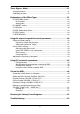
Table of Contents Introduction ................................................................................................. 1 Welcome Aboard! ....................................................................................................1 Main Features ..........................................................................................................1 A Guitarist’s Guided Panel Tour ................................................................. 3 Front panel.............................
Tuner (Bypass, Mute)................................................................................. 21 Tuning procedure...................................................................................................21 Calibrating the tuner...............................................................................................22 Explanations of the Effect Types .............................................................. 23 A. DRIVE/AMP models ..................................................
Specifications............................................................................................. 56 Appendix .................................................................................................... 57 Effect parameters...................................................................................................57 Index ...........................................................................................................
Introduction M To maximize your chances of enjoying a long and toneful relationship with your AX3000G, please read this manual at least once, and (as they say), “use the product as directed.” Keep the manual for future reference after you’ve read it; you’ll want to re-read it later at some point to pick up cool tips you may have missed the first time around.
• The AX3000G features an Expression Step Sequencer (abbreviated as ESS in this manual) that provides step control of a variety of effect parameters, giving you new possibilities of sounds that were unavailable until now. • The delayed sound can be maintained when you switch between programs that have the same delay type and TIME parameter settings. (The HOLD function of HOLD DELAY or the FREEZ function of the FREEZ effect assigned to the control switch will be cancelled at this time.
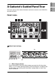
FRONT PANEL 1 5 8 Introduction Creating and Storing 4 Playing Setup Here we’re going to learn about the buttons and other controls on the AX3000G’s top and rear panel. Panel Tour A Guitarist’s Guided Panel Tour Tuner 3 Pedals Effect Type 2 7 1 EFFECT EDIT SECTION 3 Spec. 1.1 Effect Category buttons Use these buttons to select the effect category you want to edit using value knobs 1–5, or to switch individual effects on/off.
When you press a button, its LED will blink; now you can use value knobs 1–5 to edit the effect parameters of that category. If you want to turn off an effect that is currently on, press the effect category button for that effect (it will blink), and then press the button again to turn the effect off (the LED will go dark); the display will indicate “--OFF--”. 1.2 Effect Model selectors Use these to select the effect model that you want to use for each effect category.
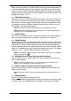
Introduction 2.2 2.1 2.2 Delay Time Tap button You can set the delay time by pressing this button at the desired interval. 2.3 ESS button Use this button when you want to start or make settings for the ESS (Expression Step Sequencer). HINT: For details, refer to “Using ESS to control a parameter” on p.45 3.2 3.3 3.4 5 Tuner Effect Type Pedals Index 3.1 Appendix Spec.
3.1 AMP/LINE button This button lets you make appropriate settings for the device to which your AX3000G is connected. The icon in the display will change depending on the destination device you’ve selected (p.12). 3.2 GLOBAL button You can press the GLOBAL button and use the √/® buttons to move through the menus in the following order. After you’ve selected a menu item, use value knob 1 or the ▲/▼ buttons to edit the value.
4.5 OUTPUT icon This indicates the AX3000G’s output destination setting (AMP/LINE). 4.8 Quick Assign icon This will light if you’re operating a parameter that can be assigned to the expression pedal, indicating that the Quick Assign function is available. Introduction Panel Tour Pedals 4.7 EXP icon This will light when the expression pedal can be used. Effect Type Tuner 4.6 CABINET icon This will light when the Cabinet model is active. Setup 4.
6 BANK/PROGRAM SELECT SECTION 6.1 6.2 6.1 BANK UP/DOWN switches In Program Select mode (p.15), pressing Bank Up will increment the bank, and pressing Bank Down will decrement the bank. In Program Select mode, you can press and hold the Bank Up switch which turns on Individual mode (the LED located at the upper left of the switch will light green). In Individual mode, you can use the program select switches to turn the Pre-Effect, Drive/Amp model, Modulation effect, and Delay effect on/ off individually.
9 Introduction Panel Tour Setup Factory settings Index Appendix NOTE: What happens when you change programs will depend on the target that’s assigned to the expression pedal, as follows. If the expression pedal is assigned to VOLUME, DELAY INPUT, or REVERB INPUT, or if it is assigned to the same target as in the previous program, the pedal position will be valid immediately after the program change, and the pedal indicator will light.
REAR PANEL 9 11 12 10 9 POWER SUPPLY DC9V Connect the included AC adapter here. 10 INPUTS AND OUTPUTS 10.1 10.2 10.3 10.4 10.5 10.6 10.1 INPUT jack Connect your guitar to this jack. 10.2 AUX IN jack (stereo mini) Connect the analog output of your audio device here. NOTE: This convenient input jack lets you connect your CD/MP3 player or other audio device and play your guitar along with a favorite song. Use the output volume of your audio device to adjust the playback volume. 10.
Introduction Setup Panel Tour 11 MIDI 11.2 MIDI IN jack This jack receives MIDI data. Use it when you want to control your AX3000G from a connected external MIDI device. Creating and Storing 11.1 MIDI OUT jack This jack transmits MIDI data. Use it when you want to control a connected external MIDI device from your AX3000G. Playing 11.2 Tuner 11.1 Pedals Effect Type 12 S/P DIF OUT 11 Index Appendix Spec. Troubleshooting Factory settings 12.
Setup NOTE: You must turn off the power of all your equipment before you make connections. If you ignore this warning, you may damage your guitar amp or speaker system, and may experience malfunctions! OUTPUT SETTINGS OUTPUT SELECT FUNCTION Here’s where to specify whether you’re connecting your AX3000G to a guitar amp or to a mixer/recorder.
2. Turn the LEVEL knob located on the rear panel of AX3000G all the way toward the left (as seen from the rear), setting the volume to 0. Introduction Panel Tour NOTE: If you want to use headphones, plug them into the PHONES jack. If you do, signal from the OUTPUT jack(s) will no longer be heard.
EXAMPLE OF CONNECTIONS TO A MIXER OR RECORDER • When using the AX3000G for direct-line recording, connect the OUTPUT L/ MONO and R jacks to the input jacks of your mixer or recorder. Be sure to select the appropriate connection (p.12). HINT: If you’re using a stereo connection, pan the input channels of your mixer/ recorder hard left and right respectively.
Settings for each effect, the expression pedal, ESS, and other functions can be given a name and stored in the AX3000G as a “program.” The AX3000G can hold 96 programs (24 banks x 4 programs in each bank), and all of these programs are rewritable. When the AX3000G is shipped from the factory, banks 1–8 contain 32 preset programs. In Program Select mode you can switch between various types of sounds by selecting the desired program. HINT: Banks 9–16 and 17–24 contain the same preset programs as banks 1–8.
OPERATIONS IN INDIVIDUAL MODE As an example, here’s how to switch the pre-effect and reverb on/off while you’re playing. 1. If the Bank Up switch LED is dark, you’re in Program Select mode. Press and hold the Bank Up switch for about one second; you’ll enter Individual mode, and the LED above the Bank Up switch will light green.
SIGNAL PATH There are two ways you can do this; by “tweaking an existing program” or by “starting from scratch.” CREATING YOUR OWN PROGRAM If you want to tweak an existing program, select one that’s close to the sound you want. Set the CATEGORY select switches to the amp, cabinet and effects you want to use, and use value knobs 1–5 to adjust the sound.
press the CABINET button once again to turn it off; the from the LCD display. icon will disappear 6. Press the NR/PROG LVL button, and adjust NR SENS (value knob 4) so that you don’t hear noise when you’re not playing your guitar. The effect will become stronger as you increase the noise reduction setting (0.2, 0.4–10.0). If this is off, no noise reduction is applied.
1. Press the RENAME button. ® buttons to move the cursor to the character you want to change 2. Use the √/® (the selected character blinks), and use value knob 1 or the ▲/▼ buttons to change the character. Introduction Creating and Storing You can use the following characters. Panel Tour NOTE: The program name is saved as part of each program. If you switch to a different program or turn off the power before you save, your settings will be lost. Setup Here’s how you can name a program.
RESTORING A SETTING TO ITS ORIGINAL VALUE (ORIGINAL VALUE) The Original Value icon in the value display gives you a way to find out the parameter values that are stored in a program. When you are using a knob or button to change the value of a parameter, the ORIG (original value) icon will appear when the value you are adjusting matches the “original value” stored in the program. HINT: So, you’re flipping through the programs on your new AX3000G, and you come across one you really like.
1. To activate the Auto Chromatic Tuner, you can either activate Bypass or Mute, or press the EXIT/TUNE button while the display shows the program name. If the display does not show the program name, press the EXIT/TUNE button to make the program name appear, and then press the EXIT/TUNE button once again. HINT: If you want to tune during a live performance, it’s a good idea to tune while Muted. 2. Play a string on your connected guitar, and the closest note name will appear in the bank display.
3. Tune your guitar while watching the tuner display or the meter in the name display. The pitch is flat The pitch is correct Tuner display Name display Tuner display Name display The pitch is sharp Tuner display Name display 4. When you’ve finished tuning, press the EXIT/TUNE button once again or press any desired program select switch. HINT: If you exit the Tuner by pressing a program select switch, this will also switch to the program you selected.
Explanations of the Effect Types T his section explains the AX3000G’s sixteen drive/amp models and eleven pre-effects, cabinet models, modulation, delay, and reverb effects. A. DRIVE/AMP MODELS The drive/amp model you select here will change the character of the tone controls and their placement within the circuitry, producing the response that’s unique to each model. This choice also selects an appropriate cabinet model. * : This indicates a parameter that you can control from the expression pedal.
AMP MODELS 9. BOUTIQUE CL (BTQ CL) This models the Clean channel of a very expensive custom-order amp. 10. BLACK 2X12 (BLK 2X12) This models a dual channel black-faced 2x12 combo amp that’s considered a “must-have” by country and blues players. 11. AC15 This is modelled from Channel 2 of an amazing sounding 1962 VOX AC15, which is part of our vast amp collection. 12.
B. CABINET MODELS The cabinet models are associated with the drive/amp models. They will have an effect only if the drive/amp model is turned on. When you change the type of drive/amp model, an appropriate cabinet model is selected automatically. You can change the cabinet model by pressing the CABINET button and turning value knob 1. If you don’t want to use a cabinet model (for example if you’ve connected the AX3000G to a guitar amp), press the CABINET button twice to turn it off.
9. UK H30 4X12 (UK H30) This models a heavy-duty closed-back cabinet containing 30-watt ceramic-magnet speakers, manufactured in the UK and dating from the late ’60s. 10. UK T75 4X12 (UK T75) This 4x12 closed-back cabinet model is a famous UK-built black box loaded with four modern 75-watt ceramic-magnet speakers. 11. US V30 4X12 (US V30) This models a black beast of a closed-back cabinet with ceramic-magnet speakers that comes from the same home in California as our US MODERN amp model.
[4] “TYPE” OFF, H-S, S-H [5] “LEVEL” 0.0–10.0 Selects the pickup conversion model. OFF: Pickup conversion will not be performed. H-S: Single-coil sound will be transformed into humbucking sound. S-H: Humbucking sound will be transformed into single-coil sound. * Adjusts the output level. 3. ACOUSTIC HINT: Single-coil pickups are recommended for best results. 4. VOX WAH This is a detailed simulation of two legendary VOX wah pedals; the V847 and the V848.
5. AUTO WAH This models an auto wah unit that automatically applies a wah effect according to your picking dynamics (i.e., the strength with which you pick the strings). As with the VOX WAH, you can select either V847 or V848 as the wah type. [1] “SENS/POL” 0u–10u, 0d–10d [2] “ATTACK” [4] “TYPE” 1.0–10.0 847/848 [5] “ORDER” PrE(PRE)/ PoS(POST) Adjusts the sensitivity of the wah to the volume of your guitar. * Adjusts the response speed. Selects either V847 or V848 as the wah type.
8. OCTAVE This models a pedal that generates a pitch one octave below the original input, mixing it with the original sound to add thickness. [4] “DIRECT” [5] “EFFECT” 0.0–10.0 0.0–10.0 * Adjusts the mix level of the original sound. * Adjusts the mix level of the note one octave below. HINT: This type of effect only works with single notes; chords will confuse it. 9. RING MOD This models the sympathetic strings (drone) of a sitar. Set the Key to match the song you’re playing.
D. MOD (MODULATION) EFFECTS Here you can select one of 11 modulation-type effects. *: This indicates a parameter that you can control from the expression pedal. 1. CLASSIC CHORUS (CL CHORS) This models a chorus unit that has two modes (chorus and vibrato), and is bestknown for being built into a guitar amp. [1] “DEPTH” [2] “SPEED” [3] “MANUAL” 0.0–10.0 0.1–10.0[Hz] 1.0–10.0 [5] “MODE” 1, 2, 3 * Adjusts the modulation depth. * Adjusts the modulation speed. * Adjusts the center frequency of the sweep.
4. BI CHORUS (BI CHORS) This is a chorus model unique to the AX3000G. It provides two chorus units, CHORUS 1 and CHORUS 2, and lets you connect the two units not only in series or in parallel, but also to synchronize or de-synchronize the two LFOs. It produces a variety of tones that cover a range from wonderfully spacious sounds to bizarre flanger-like sounds with complex modulation. [1] “DEPTH” 0.0–10.0 [2] “SPEED 1” 0.1–10.0[Hz] [3] “SPEED 2” 0.1–10.0[Hz] * Adjusts the modulation depth of CHORUS 1/2.
P2: PHASER 1/2 are connected in parallel, and their LFOs are synchronized (Stereo mode). P3: PHASER 1/2 are connected in parallel, and their LFOs are synchronized in opposite phase (Stereo mode). NOTE: If P2 or P3 is selected, the speed is adjusted by the SPEED 1 (value knob 2). 6. TEXTREM This models the popular tremolo circuit that’s built into the BLACK 2x12 model. The SPREAD setting lets you produce a panning effect that spreads to left and right. [1] [2] [4] [5] “DEPTH” “SPEED” “SPREAD” “LEVEL” 0.
8. PITCH SHIFTER (PITCH) This is a pitch shifter with a range of two octaves up or down, rivaling sophisticated rack-mounted signal processors. [1] [2] [3] [4] [5] “DEPTH” “SPEED” “MANUAL” “RESO” “MIX” 0.0–10.0 0.1–10.0[Hz] 1.0–10.0 0.0–10.0 0.0–10.0 * * * * * Adjusts the modulation depth. Adjusts the modulation speed. Adjusts the center frequency. Adjusts the amount of resonance. Adjusts the mix level of the effect. 10.
11. TALK MOD This is an envelope controlled talking modulator. The vocal character will change according to the input from your guitar. [1] “DEPTH” [2] “ATTACK” [3] “MANUAL” 0.0–10.0 1.0–10.0 1.0–10.0 * Adjusts the depth of operation. * Adjusts the speed of response. * Adjusts the vocal character. If DEPTH is set to 10, MANUAL will not function. [4] “TYPE” “A-E”–“O-U” Selects one of the following transitions between vowels.
[4] “MODE” [5] MIX Specifies the combination of heads that will be used. 1: Use one head (C). 2: Use two heads (A, B). 3: Use two heads (B, C). 4: Use two heads (A, C). 5: Use three heads (A, B, C). 0.0–10.0 * Adjusts the mix amount of the delay. 3. ANALOG DELAY (ANLG DL) [1] [2] [3] [4] [5] “TIME” 3–2700[ms] “FEEDBACK” 0.0–10.0 “TONE” 1.0–10.0 “SPEED” 0.1–10[Hz] “MIX” 0.0–10.0 * * * * * Sets the delay time. Adjusts the amount of feedback. Adjusts the tone of the delay. Adjusts the modulation speed.
6. 2TAP DELAY (2TAP DLY) This is a multi-tap delay that models the Korg DL8000R digital multi-tap delay unit. Two delays with differing delay times are assigned to L and R, turning a mono input into stereo. This can also be used as a ping-pong delay. [1] [2] [3] [4] “TIME” 1–2700[ms] Sets the delay time. “FEEDBACK” 0.0–10.0 * Adjusts the amount of feedback. “TONE” 1.0–10.0 * Adjusts the tone of the delay. “TAP TIME” 0.0–10.0 Specifies the right delay time as a proportion of the left delay time.
9. HOLD DELAY (HOLD DLY) If you assign “HOLD DLY” to the CONTROL switch, you’ll be able to hold the delay delayed sound. [1] “TIME” 1–2700[ms] Sets the delay time. [2] “FEEDBACK” 0.0–10.0 * Adjusts the amount of feedback. [3] “TONE” 1.0–10.0 * Adjusts the tone of the delay. [5] “MIX” 0.0–10.0 * Adjusts the mix amount of the delay sound. CONTROL switch HOLD DLY If you select “HOLD DLY” for the CONTROL switch, the delay sound will be held when you turn on the switch. 10.
F. REVERB EFFECTS Here you can select one of 11 reverb-type effects. *: This indicates a parameter that you can control from the expression pedal. [1] “TIME” 1.0–10.0 [2] “LO DAMP” 0.0–10.0 [3] “HI DAMP” 0.0–10.0 [4] “PRE DLY” 0–70[ms] [6] “MIX” 0.0–10.0 * Sets the reverb time. The relation between this setting and the actual length of reverberation will differ depending on the reverb type. * Adjusts the attenuation of the low-frequency range. * Adjusts the attenuation of the high-frequency range.
8. ROOM This models the reverberation of a typical room, with numerous early reflections. 9. STUDIO This models the reverberation of a large room. 10. HALL This models the reverberation of a concert hall with numerous echoes. 11. ARENA REVERB DELAY MODULATION PRE EFFECT CABINET DRIVE/AMP Effect Type Tuner This models a concert hall with smooth and dense reverberation.
Using the expression pedal to control parameters EXPRESSION PEDAL SETTINGS The AX3000G provides a built-in expression pedal that you can use to control not only wah or volume, but a wide variety of effect parameters. For each program, you can specify which effect will be controlled, and how. The effect to which the expression pedal is assigned can be switched on/off by advancing the expression pedal all the way forward to operate the switch located under the pedal.
SETTING THE EXPRESSION TARGET Introduction Panel Tour NOTE: When you change the expression target, the MIN and MAX values will be initialized. NOTE: If you change the effect type of a parameter that is assigned to the expression target, the target will be initialized to a setting of “--OFF--”. (However, “D/ INPUT”, “R/INPUT” are exceptions.) HINT: If you’ve set the Pre-effect type to “VOX WAH,” the “P/MANUAL” (wah position) will automatically be assigned to expression.
The expression pedal target is indicated as follows. “*/######” *: Target category ######: Target parameter • Examples “--OFF--” --- OFF “VOLUME” --“P/DIRECT” --“M/SPEED” “D/INPUT” “R/MIX” “A/GAIN” (controls nothing) Volume pedal DIRECT (mix amount of original sound) for a pre-effect (e.g.
USING TAP TEMPO TO SET A PARAMETER NOTE: The CONTROL switch LED will blink at the tempo you specify. NOTE: The maximum tap interval is 10 seconds. LFO START TRIGGER of the CLASSIC FLANGER effect SPEED SW of the ROTARY effect HOLD of the HOLD DELAY effect ON of the FREEZ effect NOTE: If you haven’t selected an applicable effect, nothing will be controlled.
NOTE: ESS CTL2, ESS TAP1, ESS TAP2, and ESS TRIG will do nothing if ESS is turned off. NOTE: For ESS TAP1 and ESS TAP2, the CONTROL switch LED will blink at the specified tempo. NOTE: The maximum tap interval is 10 seconds.
Introduction Panel Tour E Setup SS (Expression Step Sequencer) controls a variety of effect parameters in a stepwise fashion, letting you control your sound in completely new ways. For example, you can use the step sequencer to control the SPEED parameter of a modulation effect to create complex modulation that would not have been possible until now.
4-A1 (4 step alternate, 1-shot) 4-A.1 (4 step alternate 2, 1-shot) Advance from step 1 to step 4, then back to step 1 and stop. (1234321) Advance from step 1 to step 4, then back to step 1 and stop. (12344321) HINT: In the ESS display, a corresponding number of LEDs 1–8 will light green to indicate the last step you specify here. NOTE: If you selected a “1 shot” mode (“*-#1”), the parameter will return to the value specified by the setting of the effect when the steps have been completed.
USING THE CONTROL SWITCH TO OPERATE ESS You can use the control switch to control ESS operations such as start and stop. To do so, press the EXP/CTL button, and use value knob 5 to select one of the following ways in which the control switch will control the ESS.
Control via MIDI IDI stands for Musical Instrument Digital Interface, and is a world-wide standard for exchanging various types of musical data between electronic musical instruments and computers. When MIDI cables are used to connect two or more MIDI devices, performance data can be exchanged between the devices, even if they were made by different manufacturers. M The AX3000G can use MIDI to communicate in the following ways with another MIDI device.
4. Set the MIDI channel of your connected external MIDI device. HINT: For details on how to set the MIDI channel of your external MIDI device, refer to its owner’s manual. PROGRAM CHANGE (GLOBAL “PCHG OUT”) When you switch programs on the AX3000G, a program change message is transmitted from the MIDI OUT jack, causing an external MIDI device to switch programs. Similarly, when the AX3000G receives a program change message, its program will switch automatically.
1. Press the GLOBAL button. ® buttons to make the name display read “CCHG I/O.” 2. Press the √/® 3. Specify whether all control change messages will be transmitted or received. Use value knob 1 or the ▲/▼ buttons to make your choice. “On” allows transmitting and receiving. “OFF” disables transmitting and receiving. NOTE: If this setting is “OFF,” no control change messages will be transmitted or received even if you specify individual control change numbers in step 4.
NOTE: You can transmit data dumps regardless of the “SYEX OUT” setting. In fact, if you want to transfer program data between two AX3000Gs, we recommend that you turn the “SYEX OUT” setting “OFF.” If “SYEX OUT” is “On,” operating the knobs or other controls may change the parameters of the other AX3000G in unintended ways. BACKING UP 1. Connect the AX3000G’s MIDI OUT to the MIDI IN of the device that will receive the data dump. 2.
6. Press the AX3000G’s WRITE button to begin transmitting. When transmitting is completed, the display will indicate “COMPLETE,” and you will return to the screen of step 4. (While “DUMP ALL” is being transmitted, the display will indicate “SEND.”) NOTE: While data is being transmitted, do not touch the buttons or knobs of the AX3000G or its foot controller, and never turn off the power. RESTORING 1. Connect the transmitting device’s MIDI OUT to the AX3000G’s MIDI IN. 2.
2. If at this point you decide that you really don’t want to execute this operation, you can press the EXIT switch. 3. Press the WRITE button. The name display will show “LOADING,” and the factory-set data will begin being reloaded. When reloading has been completed, the name display will indicate “COMPLETE,” and the AX3000G will automatically switch to Program Select Mode. Introduction Panel Tour Setup Playing Creating and Storing Appendix Spec.
Troubleshooting I f you suspect a malfunction, please check the following points first. If this does not resolve the problem, please contact your dealer or Korg authorized service center. 1. Power does not turn on • Is the AC adapter connected to the rear panel DC9V jack? • Is the AC adapter plugged into an AC outlet? • Could the AC adapter be damaged? 2.
55 Introduction Index Appendix Spec. Troubleshooting Factory settings MIDI/DIGITAL ESS Pedals Effect Type Tuner Creating and Storing Playing Setup • Could “AMP/LINE” switch be set to “Ln” (LINE)? • Could LEVEL be raised excessively? →Make the appropriate settings as explained in “Basic connections” on p.12. Panel Tour 5. The sound connected to your guitar amp is distorted, or sounds wrong.
Specifications NUMBER OF AMP TYPES: 11 NUMBER OF CABINET TYPES: 16 NUMBER OF EFFECTS PEDAL TYPES: 11 MODULATION TYPES: 11 DELAY TYPES: 11 REVERB TYPES: 11 NOISE REDUCTION: 1 NUMBER OF PROGRAMS: 96 (24 BANKS x 4 CHANNELS) AUDIO INPUTS INPUT (Monaural phone jack) INSERT RETURN (Monaural phone jack) AUX IN (STEREO MINI) AUDIO OUTPUTS OUTPUT x 2 (Monaural phone jack) INSERT SEND (Monaural phone jack) PHONES (STEREO MINI) LEVEL knob (adjusts OUTPUT and PHONES) S/P DIF OUT (16-bit/44.
Introduction Panel Tour Appendix EFFECT PARAMETERS PICKUP SENS ACOUSTIC BODY VOX WAH CLOSE OPEN AUTO WAH SENS / POL ATTACK * * * ATTACK / SPEED MANUAL - - PHASE TOP * * U-VIBE / PHASE DEPTH CHORUS / FLANGER DEPTH OCTAVE - - RING MOD - FILTER DRONE - SYNTH SENS DRIVE / AMP GAIN TUBE OD GAIN SPEED SPEED - LEVEL * PHASEMIX * - * TYPE MANUAL * TYPE ORDER * * MANUAL * MANUAL TYPE ORDER * OSCFREQ LEVEL TYPE * TYPE * RESO MIX - DIRECT * EFFECT * DIRECT * E
DELAY TIME FEEDBACK ECHO PLUS TIME * FEEDBACK MULTI HEAD TIME FEEDBACK ANALOG DELAY TIME MOD DELAY TIME SWEEP DELAY TIME * FEEDBACK * FEEDBACK * FEEDBACK 2 TAP DELAY TIME FEEDBACK CROSS DELAY TIME FEEDBACK RHYTHM DELAY TIME FEEDBACK HOLD DELAY TIME FEEDBACK REVERSE DELAY TIME FEEDBACK FREEZ TIME - REVERB TIME SLAP TIME SPRING TIME BOUNCE TIME PLATE TIME GARAGE TIME CHAMBER TIME CANYON TIME ROOM TIME STUDIO TIME HALL TIME ARENA TIME TONE * * * * * *
Introduction FAT DIST 23 FILTRON 33 FREEZ 37 FUZZ 23 D DELAY 34 DELAY EFFECTS 34 DELAY FX 50 DRIVE/AMP Models 23 DRONE 29 DUMP ALL 51 DUMP CUR 51 DUO PHASE (DUO PHAS) 31 E ECHO PLUS 34 Effect On/Off mode 15 ESS (Expression Step Sequencer) 45 EXP PDL 50 N Naming 19 Creating and Storing Tuner Effect Type METAL DIST (METAL DS) 23 MIDI 48 MIDI CH 49 MIDI Channel 49 MOD DELAY (MOD DLY) 35 MOD EFFECTS 30 MOD FX 50 MULTI HEAD (MULTI HD) 34 MULTI TAP CHORUS (MT CHORS) 30 Pedals M OCTAFUZZ 23 OCTAVE 29 ORANG
RHYTHM DELAY (RHYTM DL) 36 RING MOD 29 ROOM 39 ROTARY 32 S SHRED DIST (SHRED DS) 23 SLAP 38 Sound Editor 50 SPRING 38 Storing 19 STUDIO 39 SWEEP DELAY (SWEEP DL) 35 SYEX OUT 50 SYNTH 29 T TALK MOD 34 TEXTREM 32 TUBE OD 23 Tuner 21, 40 TWEED 1x12 (TWD 1x12) 25 TWEED 1x8 (TWD 1x8) 25 TWEED 4x10 (TWD 4x10) 25 U UK ’80S 24 UK H30 4x12 (UK H30) 26 UK MODERN (UK MODRN) 24 UK T75 4x12 (UK T75) 26 UK68P 24 US MODERN (US MODRN) 24 US V30 4x12 (US V30) 26 U-VIBE/PHASE (VIB/PHAS) 28 V VOX AC15TBX (AC15TBX) 25 VOX
IMPORTANT NOTICE TO CONSUMERS This product has been manufactured according to strict specifications and voltage requirements that are applicable in the country in which it is intended that this product should be used. If you have purchased this product via the internet, through mail order, and/or via a telephone sale, you must verify that this product is intended to be used in the country in which you reside.