E 1
To ensure long, trouble-free operation, please read this manual carefully. Precautions Location Using the unit in the following locations can result in a malfunction. • In direct sunlight • Locations of extreme temperature or humidity • Excessively dusty or dirty locations • Locations of excessive vibration Power supply Please connect the designated AC/AC power supply to an AC outlet of the correct voltage. Do not connect it to an AC outlet of voltage other than that for which your unit is intended.
Handling of the internal hard disk Do not apply physical shock to this device. In particular, you must never move this device or apply physical shock while the power is turned on. This can cause part or all of the data on disk to be lost, or may damage the hard disk or interior components. When this device is moved to a location where the temperature is radically different, water droplets may condense on the disk drive.
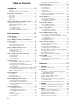
Table of Contents Introduction ...................................... 5 Features........................................................................... 5 Printing conventions in this manual........................... 7 Panel overview of the D12 ..................................... 8 Top panel ........................................................................ 8 Front panel ................................................................... 10 Rear panel ...........................................
. SONG ............................................................. 88 P6 FinalEff: Selection and settings for the final effect...............................................................108 P1 SelSong: Selecting a song ...................................... 88 P2 EditSong: Song editing .......................................... 89 P3 PrgPlay: Program playback of songs................... 90 P4 CDR/RW: Creating and playing a CD-R/RW .. 90 21. SOLO/MONITOR .........................................
44: GT6: Guitar Multi6.......................................................... 120 AS1 – AS3 Category: Guitar amp simulator.......... 120 45: AS1: Amp Simulator1..................................................... 120 46: AS2: Amp Simulator2..................................................... 120 47: AS3: Amp Simulator3..................................................... 120 PA1 Category: Pre-amp simulator.......................... 121 48: PA1: Pre Amp Simulator.......................................
Features • The D12 is a 12 track digital multi-track recorder (MTR) with full-digital processing (24 bit internal processing, 16/24 bit uncompressed recording and playback, 44.1 kHz sampling frequency). From recording to effect processing to mixing down to CD-R/RW (a CD-R/RW drive is required), all processing is performed completely in the digital domain. • It contains a 12 track recorder, a 16-channel 4-bus mixer, and effects.
• The Trigger Recording function allows recording to start automatically in response to an audio input, so that it’s easy to begin recording even when both hands are occupied in playing an instrument. You can also use a foot switch to start or stop recording. • The Scrub function lets you listen to the recorded sound of a track just as if you were manually moving the reels of an open-reel tape recorder – a great convenience when you need to find the exact beginning of a phrase.
Switches and knobs [ ] Keys, dials, and knobs on the panel of the D12 are printed within [square brackets]. LCD screens The parameter values shown in the LCD screens printed in this manual are explanatory examples, and may not necessarily match the displays that appear on your D12. Introduction Printing conventions in this manual Panel overview of the D12 Parameters that appear in the LCD screen “ “ Parameters that appear in the LCD screen are printed inside “double quotation marks.
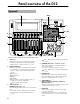
Panel overview of the D12 Top panel 1 10 11 9 12 ~ 32 2 3 8 7 4 5 * For the mic and trim controls etc., refer to the “Front panel” section. 1 2 3 8 LCD screen This displays the volume (level meters) and time locations (locate) during recording or playback, and displays the various parameters. (→p.13) [TRACK STATUS] keys These keys are used to put each track into playback or record status, or to mute (silence) it. Each time you press a key, the track setting will alternate. (→p.
9 [POWER] key This key turns the power on/off. (→p.17) 16 [SOLO/MONITOR] key This key is used to solo an individual channel, send, or return. It is also used to select an audio source for monitoring. (→p.109) When solo is on, the LED will blink. 10 HDD/CD-RW access indicator This indicator will light when the internal hard disk is being accessed for recording or playback, or when the internal CD-R/RW drive is operating.
(→p.35, 97) By holding down the [IN/LOC1] key and pressing the [OUT/LOC2] key, you can listen to the audio between the IN–OUT points. 27 [AUTO PUNCH] key This key is used to turn the Auto Punch-in/out function on/off, to set the pre/post roll time, and to verify the start/end locations. (→p.28, 98) This key will light when the Auto Punch-in/out function is on. Front panel 1 MIC (built-in mic) 2 [MIC] on indicator 3 [MIC] switch: OFF, INPUT 1, INPUT 2 OFF: The built-in mic is turned off.
[TRIM] knob: –60...–10...+4 dBu These knobs adjust the input level. The markings indicate the input level. Adjust each [TRIM] knob as appropriate for the input instrument, so that the peak indicator lights when the connected instrument is played most loudly. The input level will depend on the instrument or performance, but the approximate ranges are as follows.
8 [MONITOR OUT LEVEL] knob This knob sets the volume level from the [MONITOR OUT L/R] jacks. 9 [MASTER OUT L/R] jacks These are analog outputs for the master LR bus which combines the signals from each mixer channel, or for the audio source that is selected by the Solo function. The Solo selection is made in the [SOLO/MONITOR] “Solo” tab page. Connect your external monitor system or recording device to these jacks. They output the same audio signal as the [S/P DIF OUT] jacks. These are RCA phono jacks.
Introduction Objects in the LCD screen and their functions f: Dialog box Objects in the LCD screen To select an object displayed in the LCD screen, use the [CURSOR] key to select it, and press the [ENTER] key. Select the “OK” button to execute the function (or select the “Cancel” button to cancel without executing), and press the [ENTER] key. The dialog box will close.
Adjusting the LCD screen contrast Use the rear panel [LCD CONTRAST] knob to adjust the contrast. (→p.11) Basic operation 3. Selecting and setting a parameter Selecting a parameter To edit a parameter, use the [CURSOR] key to move the edit cell to the parameter that you wish to edit, highlighting that parameter. In a list display screen, you can rotate the [VALUE] dial to move the edit cell. Setting a parameter value 1.
Basic operation Basic operation Starting Step 0. Starting Connecting instruments and turning on the power Connect the instrument and mic etc. that you wish to use for recording to the D12, and turn on the power. (→p.17) Making connections, and turning the power on/off Creating/selecting a song In this step, the song you mixed down to tracks 1 and 2 can be written to a CD. Play back tracks 1 and 2 to hear the result of your mixdown. Tracks 1 and 2 will be written to the CD.
Connect instruments and turn on the power →Step 1 Create a new song →Step 2 Record →Step 3 Assign mixer channels • Apply effects to the input sound (Step 8) • Apply EQ Recording →Step 4 Overdubbing →Step 4 Adjust the recording level Playback →Step 5 Editing →Step 10 • Track editing • Punch-in/out →Step 9 Mixdown →Step 7 Adjust the track balance • Apply effects to the tracks • Apply EQ to the tracks • Apply master effects Final effect Scenes →Step 8 Bounce to tracks 1 and 2 →Step 4 Creat
Use the [PHONES LEVEL] knob to adjust the volume. 1. Connections Make the appropriate connections for your system, substituting your own equipment as necessary for the equipment shown here. The diagram below shows a basic example of connections when using the D12 to record. For details on installing the CDRW-1 CD-R/RW drive option, refer to p.133. [PHONES] jack The audio signal that is output from the [MONITOR OUT L/R] jacks and the [PHONES] jack is set in the [SOLO/MONITOR] “Monitor” tab page. (→p.
A guitar or bass guitar that is being sent through a compact effect device can be connected to [INPUT 1]–[INPUT 4]. When inputting in stereo, you should select two adjacent inputs (1–2, 3–4) so that track editing can be performed more efficiently. If you are recording from a connected mic, locate the mic at a sufficient distance from the D12 so that it does not pick up noise.
1 If you wish to keep any effect settings that you edited, save them. (→p.46) 2 Lower the [MASTER] fader of the D12 to the –∞ position. Lower the volume of any external devices to the minimum position. 3 Turn off the power of the monitor system to which the D12 is sending audio, and the power of any external output devices such as an MD. 4 Press and hold the [POWER] switch of the D12 to turn off the power. When you press the [POWER] switch a dialog box will appear, asking you to confirm.
20
In order to record a new song, you must first create the new song. Here’s how to create a song, assign a name to it, and select songs. Basic operation Step 2. Creating/selecting a song 2. Naming a song 1. Creating a new song 1 Press the [SONG] key to access the “SelSong” tab page. We recommend that you assign a name to the song before recording it, so that it can be distinguished from other songs. If you wish to change the name of another song, select that song before you begin the following procedure.
3. Selecting another song 3 Rotate the [VALUE] dial to select a song in the song list. Then select the “OK” button and press the [ENTER] key. This section explains how to select songs. There are three ways to select an existing song. To change the drive [STOP] key + [FF] key, [STOP] + [REW] key To change the drive, select the “Drive” button, press the [ENTER] key, and select a drive from the list. Select the “OK” button and press the [ENTER] key to return to the song list.
The D12 provides four channels of analog input and one (two-channel) digital input jack. In order to record the audio signals from these inputs, they must be assigned to mixer channels. If the CDRW-1 CD-R/RW drive option (sold separately) is installed, you can also assign the signal from an audio CD to the mixer channels. Digital In Dr Ch1: Track 1 Ch2: Track 2 Ch3: Track 3 Before you proceed, create a new song as described in “1. Creating a new song” (→p.21).
Play your guitar to input sound, and the level meter of Ch.1 will move accordingly. Adjust the INPUT 1 [TRIM] knob while watching the level meter. Raise [TRIM] as far as possible without allowing the level to reach CLP when you play the guitar most strongly. 5 Audition the sound. • Set the [MASTER] and [CHANNEL 1] faders to unity gain (0 dB). • Access the [SOLO/MONITOR] “Monitor” tab page. • Select the “MasterLR” button and press the [ENTER] key to turn it “On” (highlighted).
2. Digital input The D12 can record a digital audio signal that is input via the S/P DIF jack. The S/P DIF input has a built-in sampling rate converter. Sources with sampling rates of 48 kHz or 32 kHz can be connected directly, and will automatically be converted to 44.1 kHz. Here we will explain how the audio from a CD player connected to the [S/P DIF IN] jack can be input to mixer channels 1 and 2. 5 Check the recording mode and input level, and audition the sound.
26
During recording, the audio signal flows in the order of input → mixer channel → recorder. 1. Adjust the recording level, and record Here’s how to record the audio that you specified in “Assign audio inputs to the mixer” (→p.23). If you wish to create a new song and record into it, refer to “1. Creating a new song” (→p.21). Make sure that the [RHSL] key is Off. 1 Check the recording mode. Access the [RECORD] “RecMode” tab page. Set “Select RecMode” to “Input” (i.e., the audio input will be recorded).
3. Playback while recording addition tracks: Overdubbing The process of listening to previously-recorded tracks while you record additional tracks is called overdubbing. For example, this can be used to record a solo while you listen to previously-recorded backing tracks. • Select the signal that you wish to monitor. (→p.110) • Turn the “AutoIn” button “On.” (→p.110) If the “AutoIn” button is “Off”, you will always hear the input signal that is assigned to the recording track.
1 Access the [AUTO PUNCH] “AtPunch” tab page. 2 Register IN (punch-in) as the time at which recording will begin, and OUT (punch-out) as the time at which recording will end. For details on registering the IN and OUT times, refer to p.35. In the [AUTO PUNCH] “AtPunch” tab page, you can select the “Wave” button and press the [ENTER] key to register the IN and OUT points while viewing a waveform display. The time locations you register will be overwritten onto the [IN/LOC1] key and [OUT/LOC2] key.
9 Begin bounce recording. Press the [REC] key to enter record-ready mode (LED blinking), and then press the [PLAY] key to begin recording (LED lit). 0 When recording is finished, press the [STOP] key to stop. A Listen to the recording. • Press the [TRACK STATUS] keys of the recording tracks (1 and 2) to set them to PLAY (LED lit green). • Either lower the faders of the other channels, or turn the [SOLO/MONITOR] “Solo” tab page “1–2” setting “On.
Trigger recording This is a function that uses the input level (trigger) to initiate recording. Recording will begin at the instant that sound is input to the D12. • Set “PreRoll” to specify the length of playback prior to the beginning of recording, and set “PostRoll” to specify the length of playback after the end of recording. Set “Unit” to select the units in which the pre/post-roll times are set. • When you have made these settings, select the “OK” button and press the [ENTER] key.
In addition to the recording methods described above, the following possibilities are available when recording on the D12. For details refer to the page listed. • Apply EQ to the audio being recorded. (→p.38) • Apply effects to the audio being recorded. (→p.44) • Listen to the internal rhythm while recording your performance. (→p.61) • Record the internal rhythm. (→p.61) • Rehearse the recording. (→p.
1. Playback 1 Select the track(s) for playback. Press the [TRACK STATUS] keys for the tracks that you wish to play, to put them in PLAY mode (LED lit green). 2 Move to the time location from which you wish to playback. For details on changing the time location, refer to p.35. 3 Begin playback. Press the [PLAY] key. (The [PLAY] LED will light.) 4 Stop playback. Press the [STOP] key. (The [PLAY] LED will go dark.) You can also use a PS-1 foot switch (separately sold option) to start and stop playback. (→p.
34
This section explains how you can move the counter that shows the current location within the song. 1. Switching the counter display You can switch the units of the current time shown by the counter. 1 Select the “ ” button located at the left of the counter, and press the [ENTER] key to access the “Select TimeDisp Type” dialog box. Basic operation Step 6. Changing the time location Using the [FF] or [REW] keys to move Moving backward Press the [REW] key to move toward the beginning of the song.
Moving to a locate point When you press a previously-registered [IN/LOC1], [OUT/LOC2], [TO/LOC3], or [END/LOC4] key, you will move to the registered location. Using marks to move the time location You can register a specific location in a mark, and then move instantly to the registered location. A name can be assigned to each mark, and used to navigate within a song. Up to 100 marks can be registered in each song.
For details on adjusting the effects, refer to p.43 1. Adjusting the volume The input or recording/playback volume is adjusted by the [CHANNEL] faders. Raise or lower the faders to adjust the volume. (→p.112) The volume can be adjusted from silence (–∞) to unity gain (0 dB) to +12 dB gain.
Mid EQ • For the channel that you wish to adjust, select “Mid EQ Cutoff Frequency (F),” and rotate the [VALUE] dial to set the cutoff frequency. The value is displayed in the upper left of the screen. • For the channel that you wish to adjust, select “Mid EQ Gain,” and rotate the [VALUE] dial to set the gain. The value is displayed in the upper left of the screen.
You can select more than one signal to solo. 3 Adjust the monitor volume. Use the [MONITOR OUT LEVEL] knob to adjust the monitor volume of the [MONITOR OUT L/R] jacks, and use the [PHONES LEVEL] knob to adjust the monitor volume of the [PHONES] jack. Adjusting the cue level Since the [CHANNEL] faders of the D12 adjust both the recording level of the tracks and the volume level of each channel, the recording level and the monitoring level will be the same.
Registering a scene 1 Move the current time to the location at which you wish to register the scene. Use the counter or [FF]/[REW] keys to move. (→p.35) 2 Adjust the mixer settings. Adjust the [CHANNEL] faders, [PAN] knobs, EQ and effect settings. 3 Register the scene. • Press the [STORE] key to capture the current time location. • When you press the [SCENE] key, the registration destination scene number “SCENE ***” will be displayed, and the settings will be registered.
Here’s how to move a registered scene to another time location. 1 Recall the scene. As described in “Recalling a scene,” recall the scene that you wish to move. 2 Move the time location of the scene. • Select the “EditLoc” button and press the [ENTER] key. • Specify the time location in the dialog box, select the “OK” button and press the [ENTER] key to execute the move.
42
Overview of the effects In the case of a 24 bit song, only six effects will be available. On the D12, you can use up to eight insert effects that can be inserted into an analog input or mixer channel, two master effects that can be applied to the send from each channel, and a final effect that can be applied to master LR as the last stage. Each of these effects are independent, meaning that you can use a maximum of eleven effect programs simultaneously.
1 in 1 out x 4 (mono-in/mono-out × 4) • While recording four vocals simultaneously, you could apply Exciter-Comp to voices that lack impact, and apply Limiter-P4EQ to loud voices as you record. Other examples are shown below.
Here’s how an insert effect can be inserted into a mixer channel, and applied to the track playback. 1 Select the track(s) that you wish to playback. Press the [TRACK STATUS] key of one or more recorded tracks to set their status to PLAY (LED lit green). 2. Master effects The D12 contains two master effects (MstEff1 and MstEff2) which can be used simultaneously. You can adjust the send amount from each channel to change the depth of the effect.
3. Final effect One stereo-in stereo-out effect is provided as the final effect. It applies to the master LR output (→diagram on preceding page). 4 View the effects and chain that make up the program. Select the “(EffectProgramName)” button and press the [ENTER] key to access the “EffectAlgorithm” dialog box that displays the structure of that effect program. The final effect is used mainly for dynamics processing (compression etc.) to make the overall level more consistent.
Controlling an effect from an external device You can use an expression pedal or external MIDI controller to control an insert effect in realtime. Basic operation 8 Save the effect program. • If the song is playing, press the [STOP] key to stop it. • Select the “Store” button, and press the [ENTER] key to access the “StoreEffect” dialog box. • Specify the number for storing, select the “Exec.” button, and press the [ENTER] key to save the effect program.
• Select the “Cntrl Icon” button and press the [ENTER] key to access the “ControlDevice” dialog box. Using an external effect A send signal can be output from the [AUX OUT] jack, and processed by an external effect. The output of the external effect can then be returned to the [INPUT 1]– [INPUT 4] jacks and sent to the desired channels or to the master LR bus. • Select “Param,” and rotate the [VALUE] dial to select the parameter that you wish to control.
You can use mixer settings such as EQ, faders, and effects to adjust the audio from each recorded track, and combine the result into two tracks to create your own CD or record it on an external two-channel recorder (DAT recorder, MD recorder, cassette recorder etc.) to create a finished song. This process is called mixdown. If you use “4X” to write, you must use a drive that supports 4X speed writing. • A message of “Obey Copyright Rules” will appear. 1.
2. Recording to a master tape 1 Listen to the completed song. Use the faders and knobs to adjust the volume and pan of each track, and listen to the playback. 2 Connect your external recording device. Refer to “Connections for mixdown” (→p.18). 3 Record on your external recording device. • Playback the D12 song, and adjust the recording level on your external recorder. • Begin recording on your external recording device, and playback the D12.
1. Track editing functions The following functions are provided for track editing.
2. Track editing examples Copying track data: Copy Track The Copy Track command copies recorded track data from the specified region (IN–OUT) to another location (TO). • You can copy the IN–OUT data not only once, but multiple times in succession. • You can copy not only a single track, but multiple tracks simultaneously. • By using the clipboard, you can copy track data to another song. This command can be used in ways such as the following.
Here’s how to insert a blank into the IN–OUT region of track 1. 1 Register the IN and OUT times. (→p.97) 2 Select the Insert command. In the [TRACK] “EditTrk” tab page, set “EditType” to “InsertTrack.” DestTrack 3 Select the number of the track into which you wish to insert a blank. Set “DestTrack” to track 1. 4 Execute the editing command. Select the “Exec.” button and press the [ENTER] key. The display will ask “AreYouSure?,” so select the “Yes” button and press the [ENTER] key to execute the command.
Procedure for reversing track data (Reverse) Here’s how to reverse the IN–OUT region of track 1, and copy it three times to the TO location of track 2. 1 Register the IN, OUT, and TO times. (→p.97) 2 Select the Reverse command. In the [TRACK] “EditTrk” tab page, set “EditType” to “ReverseTrack.” SourceTrack DestTrack Times 3 Select the reverse source track number. Set “SourceTrack” to track 1. 4 Select the reverse destination track number. Set “DestTrack” to track 2.
Expanding or compressing a track: Expansion/Compression Track This command expands or compresses the specified region (IN–OUT) of recorded track data into the specified region (TO–END) of a specified track. • The original data is left unchanged, and the timeexpanded/compressed result is created in another track. • You can select whether or not the pitch will be converted. • Not only a single track, but multiple adjacent tracks of data can be converted simultaneously.
6 Verify that the data was copied correctly. Play back from the beginning of the song, and verify that the data was copied correctly. You can use Undo to return to the state before executing the command. (→p.99) Procedure for copying to a V-track SourceTrack DestTrack DestVTrack Here’s how V-track “a” (=currently selected) of track 1 can be copied to V-track “b” of track 1. 2 Select the swap source track number. Set “SourceTrack” to track 1. 1 Verify the copy destination.
Procedure for fading-out This command fades-in or fades-out the specified region (IN–OUT) of recorded track data. By using fadein and fade-out in conjunction with each other, you can create cross-fades. Here’s how to fade-out the IN–OUT region of track 1. • You can fade-in or fade-out the IN–OUT region. • Not only a single track, but multiple tracks of data can be faded in or out simultaneously. 2 Select the fade-out command. In the [TRACK] “EditTrk” tab page, set “EditType” to “FadeTrack.
DestTrack 3 Select the normalize destination track number. Set “DestTrack” to track 1. 4 Execute the editing command. Select the “Exec.” button and press the [ENTER] key. The display will ask “AreYouSure?,” so select the “Yes” button and press the [ENTER] key to execute the command. When processing is completed, the display will indicate “Completed.” Select the “OK” button and press the [ENTER] key. 5 Verify that the data was processed correctly.
Basic operation Step 11. Song editing On the D12, songs can be edited in the following ways. Undo is not available for song editing. 2. Examples of song editing Copying a song 1. Song editing procedure This command copies the currently selected song to a song number in the specified drive. Basic procedure for editing a song • You can use this to save a backup of your song on a different hard disk drive. • You can use this when creating different mixes or arrangements of the same song.
2 Select the Protect Song command. In the [SONG] “EditSong” tab page, set “EditType” to “ProtectSong.” SourceSong DestSong 3 Verify the song to be moved. Make sure that the move source song is selected in “SourceSong.” 4 Select the move destination song number. Use “DestSong” to select the move destination song number. 5 Execute the editing operation. Select the “Exec.” button and press the [ENTER] key.
When you have a sudden idea for a song, you can record your performance immediately, using the builtin rhythms as a guide. By joining various rhythm patterns, you can also create drum patterns for an entire song. 1. Specifying and playing a rhythm ● Access the [TEMPO/RHYTHM] “SetUp” tab page. The settings described below are made in this page. 2. Recording your performance while you listen to the rhythm You can record your performance while listening to the built-in rhythm as a guide.
• Access the [TEMPO/RHYTHM] “TmpMap” tab page. 4. Setting the tempo The tempo of a song can be controlled by the following tempo sources. • Manual tempo • Tempo map • Tempo track (MIDI clock or tap tempo) You can select one of these sources and use it to control the tempo of the song as well as to control the tempo of an external MIDI device that is synchronized to the D12. ● The tempo source is selected by the [TEMPO/ RHYTHM] “SetUp” tab page item “TempoSource.
Undo is not available for this operation. • To modify the settings, select the “Edit” button and press the [ENTER] key to access the dialog box. Modify the parameter settings as desired. 6 When the MIDI sequencer finishes playing back, stop the MIDI sequencer. The D12 will stop recording, and will display “Complete.” Select the “OK” button and press the [ENTER] key. Basic operation Select the “OK” button and press the [ENTER] key, and the tempo map you selected in step 1 will be deleted.
5 Record the tap tempo. • Select the “RecStart” button and press the [ENTER] key to put the D12 in record-ready mode. • Press either the [PLAY] key or the foot switch, and playback and recording will begin simultaneously. • While listening to the playback, press either the [PLAY] key or the foot switch at the intervals you selected in step 4, to record the tap tempo. A counter will be displayed while tempo is being recorded.
A word about data There is always a remote possibility that the D12 will malfunction, causing errors in the data or loss of data. If the D12 malfunctions, recorded data or other types of data may be lost. Please copy or back up your important data on an external drive such as a hard disk or removable disk. Korg disclaims all responsibility for any damages that may result from loss of data.
Backup procedure Restore procedure 1 Insert a disk into the backup destination drive. 1 Select the restore destination drive. Use the [SONG] “SelSong” tab page or the [SYSTEM] “DiskUtil” tab select the restore destination drive. 2 Select the backup source drive. Use the [SONG] “SelSong” tab page to select the backup source drive. If you are using “Backup1Song,” select a song in that drive. Select the song as described in “3. Selecting another song” (→p.
Here’s how to connect external drives such as hard disks, removable disks, or CD-R/RW drives. • Maximum capacity of external drive: 1,000 Gbytes per drive • Connector: D-SUB half-pitch 50 pin SCSI cable • Number of units that can be connected: up to 7 units Please use the recommended drives for external connection. For a list of recommended drives, refer to the Korg website or contact your Korg dealer. 1 Turn off the power of the D12 and the external drive.
Exchanging removable disks If the currently selected song is on a removable disk, use the following procedure to exchange disks. 1 Access the [SYSTEM] “DiskUtil” tab page. Use “DriveID” to select the drive. 3 Select the WAV file. Press “WavFileList” button to access the dialog box. In this example, select “A:Sound001.wav.” Then select the “OK” button and press the [ENTER] key to return to the [TRACK] “Import” tab page. When importing from a CD, sub-directories are also supported.
7 Select the Export command. Select the [TRACK] “Export” tab page. Basic operation The longer the import source file, the more time this operation will take before the “Completed” message appears. 6 Register the TO time location. 7 Select the Copy command. In the [TRACK] “EditTrk” tab page, set “EditType” to “CopyTrack.” 8 Select the clipboard as the copy source track number. Set “SourceTrack” to “Clip1.” The number indicates the number of tracks in the clipboard.
Drive and data compatibility within the Digital Recording Studio series This section explains how backup data and playable drives used to create D8, D16, and D16V2 songs can be used with different models of the Digital Recording Studio series. Using D8 backup data on the D12 In order to use a D8 song on the D12, you must backup the song on removable media, and restore it on the D12. Only the audio data will be restored into a new song.
This section explains how the D12 manages disk capacity. It is not necessary that the Optimize Track operation explained here be used frequently. It is sufficient to use it only if “Disk Busy” is displayed when you are actually editing, or if you wish to recover more disk free space after you have finished the song. For explanatory purposes, we will assume that you have recorded a song with the following structure.
Example 3 Suppose that you recorded A and B on track 1 as the first take. Then you overwrote the Intro, A’, B’, and Solo as take 2. A The following functions of the D12 support FAT16 DOS format. CD, CD-R, and CD-RW are exceptions. B • WAV file import • WAV file export • System software update Take 1 Take 1 Take 2 Intro A' B' Solo In this case, the take 1 data for A and B will remain underlying A’ and B’ of track 1.
What is MIDI? MIDI stands for Musical Instrument Digital Interface, and is a world-wide standard that allows a variety of musical information to be exchanged between electronic musical instruments and computers. 1. MIDI connections Special MIDI cables are used to transmit and receive MIDI messages. Connect these cables between the MIDI connectors of the D12 and the MIDI connectors of the external device with which you wish to exchange data.
Synchronizing two D12 units Here’s how you can synchronize two D12 units. One D12 will be the master, and the other will be the slave. Make connections as follows. MTC “MTC Slave” MMC “Receive” MTC “MTC Mstr” MMC “Transmit” MIDI OUT MIDI IN D12 (Master) 2 Enable control change transmission on the D12. In the [SYSTEM] “MIDI” tab page, turn the “Mixer Control” parameter “Control Change: Trans” to “ON.” D12 (Slave) 1 Make settings on the master D12.
The counter located in the upper right of each page shows the current location of the recorder. SYSTEM RECORD Counter: Counter display 2. SYSTEM P1 Control: Foot switch/control change device (pedal/MIDI) settings To change the current time of the counter, move the cursor to the counter value, and use the [VALUE] dial to change the value. (→p.
Connect the MIDI OUT of your external MIDI device to the [MIDI IN] connector on the D12, and transmit the selected MIDI data from the external MIDI device to control the effect. CC(Control Change) #000…119: MIDI control change messages can be used to control the effect. Connect the MIDI OUT of your external MIDI device to the [MIDI IN] connector on the D12, and transmit the selected MIDI control change message from the external MIDI device to control the effect. 4. Ass(CtrlChgAssign) ....................
The D12 transmits and receives MMC (MIDI Machine Control) messages. When synchronizing two D12 units, or when using the D12 together with an MMC-compatible MIDI sequencer, you can playback, stop, or fast-forward etc. by operating only the master device. Some MIDI devices may not respond to the MMC functionality of the D12. Details on the MMC functionality of the D12 are given in the MIDI implementation.
Format Type........ (P, B, D8[B], D16[P], D16[B], Audio) This shows the format type of the drive. The internal drive of the D12 and external drives that were initialized or formatted by the D12 will be displayed as “playable” drives that can be used to create and play songs. All other drives will be displayed as “backup” drives.
4. Destination ........................ [(I, A...G)/001...100, ***] This shows the restore destination drive, and lets you select the song number. If you are restoring one song, it will be restored to the song number that you select here. If you wish to restore all songs, choose “***.” The drive of the song you selected in [SONG] “SelSong” tab page will be displayed. (→p.88) 5. Exec. (Execute)......................................................... Execute the Restore command.
Initialize: The drive selected by “Drive ID” will be initialized. Format: The drive selected by “Drive ID” will be formatted. P2 Bounce: Settings for bounce recording For the procedure of bounce recording, refer to p.29. Force ......................................................... [On, Off] This setting allows a disk to be formatted or initialized even if it contains a protected song. On: Even if the disk contains a song protected by “Protect Song,” initialization will be performed forcibly.
Refer 4. TRACK P3 EditTrk: Track editing 6 5 4 Editing will apply to currently selected tracks 1–12 (→”Vtr1–6,” “Vtr7–12”). Virtual tracks that are not selected will not be affected by editing. (However, “CopyWholeTrack” and “SwapWholeTrack” are exceptions.) 1 The range (area of time) that will be edited is determined by the time locations that are registered in the [IN/LOC1], [OUT/LOC2], [TO/LOC3], and [END/LOC4] keys. (→p.35, 97) 1. Select VirtualTrack ...................
2. SourceTrack .......... [1...12, 1–2...11–12, 1–4...9–12, 1–6, 7–12, 1–12, Clip#*1] Select the copy source track. *1: “Clip#” can be selected only if the clipboard contains data. # is the number of tracks in the clipboard. You can use “Clip#” to copy data from the tracks of another song. When data is copied between songs of differing “Bit” (quantization) settings, the data will be handled as 16 bit data at the copy destination.
2. SourceTrack ............................................................ [1...12, 1–2...11–12, 1–4...9–12, 1–6, 7–12, 1–12] Select the swap source track. EditType: “DeleteTrack” This operation deletes the track data from the IN–OUT range of the delete destination track (“DestTrack”). When this is executed (“Exec.”), the data of the IN– OUT range will be discarded, and any track data that followed the deleted range will be moved toward the beginning of the song. 3. DestTrack.............................
Here you can set the editing locations (IN, OUT, TO) more precisely. (→p.81 EditType: “CopyTrack”) IN OUT A B C ... EditType: “OptimizeTrack” This operation optimizes the track data of the IN–OUT range of the optimize destination track (“DestTrack”). The D12 will not generate unnecessary sound if the IN– OUT range contains unused blank portions.
Refer 2. SourceTrack ............................................................ [1...12, 1–2...11–12, 1–4...9–12, 1–6, 7–12, 1–12] Select the swap source track. When this is executed (“Exec.”), the copy destination track will be overwritten. In the case of a 24 bit song, only tracks 1–6 can be selected. 5 3 4 3. DestTrack................................................................ [1...12, 1–2...11–12, 1–4...9–12, 1–6, 7–12, 1–12] Select the swap destination track.
8a. SelectFadeMode....................................... [A...F] A type: This curve is ideal for conventional fade-in. B type: This curve is ideal for creating cross-fades where two tracks are faded-in/out at the identical time location. C type: This curve inverts the A curve, lengthening the sound that is heard. D type: Fade-out using the A type curve. E type: Fade-out using the B type curve. F type: Fade-out using the C type curve.
SAMPLE RATE NOT 44.1k: This will appear if the sampling frequency of the WAV file is other than 44.1 kHz. SAMPLE BIT NOT FIT: This will appear if the quantization of the WAV file is other than 8 bit, 16 bit, or 24 bit. ILLEGAL WAV DATA: This will appear if the WAV file is unsupported for a reason other than the above. 3. DestTrack........................ [1...12, 1–2...11–12, clip#] Select the import destination track. Clip# will be 1 if the selected WAV file is monaural, or 2 if the file is stereo. 4.
3. Rename .................................................................. Select the “Rename” button, press the [ENTER] key to access the dialog box, and modify the song name. A name of up to sixteen characters can be input. (→p.21) 5. SONG P1 SelSong: Selecting a song 1 2 3 4 1. SongNumber ............................[I, A…G/001…100] Select the song. The display shows the drive, song number, and song name. If a 24 bit song is selected, the display will indicate “ .
Refer Undo is not available for this operation. P2 EditSong: Song editing 1 4 5 EditType: “MoveSong” The currently selected song will be moved to a different song number within the same drive. 1 4 3 The song affected by editing will normally be the currently selected song. (However the “CopyAllSong” operation will affect all songs.) 2 Undo is not available after these operations. 1. EditType ...............................
No writing and delete operations can be performed when protect is on, including recording, track editing, and registering a scene. When protect is turned on, the settings of a song will also be stored. Fader and EQ etc. will reflect your editing, but will not be stored. P3 PrgPlay: Program playback of songs You can create a program play list to arrange songs in a desired order, and play them consecutively. For settings and playback procedure, refer to p.33. 1 3 1 2 3 2 4 2. DestSong .................
6 7 4 5 1. CD-R/RW Infomation ............................................... (Trk01...99, BlankDisc, NoAudioTracks, NoDrive) This shows the song on the CD-R/RW that will be played. Trk01...99: The song number within the CD-R/RW disc. BlankDisc: An unwritten CD-R/RW disc is inserted. NoAudioTracks: Either a CD-R/RW disc has not been inserted, or no playable audio tracks were found on the disc. NoDrive: No drive is connected. 2. Size/DeviceType ...................
7. MARK 8. SCENE You can register a specific time location in a Mark, and then jump instantly to that location when desired. Since you can assign a name to each mark, you can use them to indicate sections within your song. The mixer settings that you adjust can be registered at a desired time location as a Scene, and used to automatically change the mixer settings as the song plays (when Scene Read is turned “On”). Scenes can also be used as general-purpose settings, and recalled and used when desired.
3. SceneNumber........................................ [001…100] This recalls the mixer settings of a scene to the current time location. This is also used to recall a scene when you wish to modify its name or to change its time location. The time location at which the scene is registered is shown beside “SceneNumber.” If “SceneRead” (P1-1) is “Off,” you can select any desired scene. If this is “On,” the scene for the current time will be selected automatically, and cannot be selected manually. 4. Sort.....
P2 MixView: Pan/fader scene display 1 2 Here you can make tempo, time signature, and rhythm (metronome) settings for a song. When the counter is displaying “MBT” (measures, beats, and 1/96th of a beat) (→p.75), it will operate according to the specified tempo. Tempo/rhythm can also be viewed in the [SONG] “SelSong” tab page (→p.88). 3 4 1. Pan/Balance........ (Pan1…Pan6, Bal7–8…Bal11–12) This shows the currently selected pan and balance settings.
Refer P2 TmpMap: Editing the tempo map By creating a tempo map, you can cause the tempo, time signature, and rhythm pattern to change while the song is recorded or played back. For details on creating a tempo map, refer to p.62. Changes in tempo, time signature, or rhythm can be made only at the beginning of a measure. 5. RhythmVol............................................. [000…100] Specify the volume of the rhythm.
2f. Insert.................................................... [On, Off] On: The new tempo map will be created in Insert mode, inserting the tempo map. Off: The new tempo map will be created in Overwrite mode, overwriting the existing tempo map. 3. Edit......................................................................... Here you can edit the settings of a tempo map. Select this when you wish to modify an existing map. Use “TempoMap” to select the map that you wish to modify, and then press this button.
If locations in the song have been registered to the [IN/ LOC1], [OUT/LOC2], [TO/LOC3], and [END/LOC4] keys, you can use them to perform the following functions.
4a. PreRoll .................................................[00…10] Set the pre-roll time. 11. AUTO PUNCH 4b. PostRoll................................................[00…10] Set the post-roll time. P1 AtPunch: Settings for auto punch-in/out recording 4c. Unit ..............................[Second, Meas(Measure)] Select the units for the pre/post roll times. You can select either seconds or measures. Press the “OK” button, and the specified pre/postroll times will take effect.
Refer 12. LOOP 13. UNDO 4 2 3 1. Loop.......................................................... [On, Off] Turn loop playback on/off. On: Playback will occur repeatedly over the IN–OUT range. When “On,” the [LOOP] key will light. Off: Playback will be normal. 2. In .................................................... (000:00.000…) This shows the loop start time. To set this time location, use the [STORE] key and [IN/LOC1] key, or use “Wave.” 3. Out .................................................
14. TRIGGER Trigger Recording is a function that starts recording when the volume of the input sound exceeds the threshold level that you specify. P1 Trigger: Settings to start trigger recording 1 2 3 Trigger on Threshold PreTriggerTime Time at which recording begins 1. TriggerRec.................................................. [On, Off] Turn the trigger recording function on/off. On: When in record-ready mode, input sounds that exceed the threshold level will initiate recording.
15. SCRUB Scrub, Play From/Play To, and Slow Play functions can be switched on/off here. Each time you press the [SCRUB] key, the setting will be switched on or off. By using these functions, you can register Locate and Mark times more precisely and easily. 1 2 3 On ([SCRUB] key lit): The following functions will be available. Refer 2. TrackSelect...............................................[Trk1…12] Select the track that will be played and whose waveform will be displayed.
3. SubIn ...................................................................... 17. INPUT 3a 3b 3c P1 Ch1–6: Select the inputs for mixer channels 1–6 3d Make these settings when you wish to use the inputs as “sub inputs” for inputting the return from an external effect to the [INPUT 1/GUITAR IN]– [INPUT 4] jacks, or so that the sound of an instrument connected to these jacks can be mixed with the track playback. (→p.
4b. Select Function.................... [Eq, Send, Aux, Pan] Select the functions that will be paired for the channels selected by “Select ChannelPair.” For the functions “EQ”–”Pan” that you wish to pair, press the button to enable pairing (the button will be highlighted). The settings will be applied when you press the “OK” button. When pairing is on, the pairing function will always apply to the fader and track status. P2 Ch7–12: Select the inputs for mixer channels 7–12 4. InputMid.....................
18. EQ/PHASE P3 Eq7–12: EQ settings for mixer channels 7–12 Here you can apply EQ (equalizer) to the playback of tracks 7–12. Refer to “P1 Eq1–4: EQ settings for mixer channels 1– 4.” P1 Eq1–4: EQ settings for mixer channels 1–4 Here you can apply EQ (equalizer) to the playback of tracks 1–4. Use these settings when you wish to apply EQ to the playback. P4 Phase: Phase settings for mixer channels The EQ has three bands.
19. INSERT EFFECT The insert effects can be applied to the analog inputs during recording, or to track playback. The D12 lets you use up to eight different insert effects simultaneously. Refer 3. InsertTo................................................................... Select the location at which the insert effect will be inserted. Press the “ ” button to access the dialog box and make settings. Press the “OK” button to execute your settings, or press the “Cancel” button to cancel them.
3b. Effect On/Off .......................................[On, Off] Turn each effect on/off. On: The effect is on. Off: The effect is off. P2 InsEff1: Selection and settings for Insert Effect 1 4 5 6 1 2 4. Bypass .................................................................... This lets you compare the sound processed by the effect with the unprocessed effect. Press the “Bypass” button to bypass the effect (the unprocessed sound will be heard). 3 1. InputLevelMeter.................................
Refer 20. MASTER EFFECT/AUX/ FINAL EFFECT P3 InsEff2: Selection and settings for Insert Effect 2 Select insert effect 2 and make settings for it. For details refer to “P2 InsEff1: Selection and settings for Insert Effect 1.” The master effects are used by sending an adjustable send amount from each channel to the effect. They can be used to adjust the overall depth and balance. The D12 provides two master effects. The final effect is used to adjust the final stage of the master LR bus.
5. RetBal...........................................[L63…CNT…R63] Adjust the return balance from the master effect to the master LR bus. “L” and “R” indicate L (left) and R (right) of the master bus. 6. Bypass.................................................................... Refer to “Bypass” for the insert effects (→p.106). 7. Rename .................................................................. Here you can modify the name of the effect program.
Refer 1. OutputLevelMeter .................................................... (OUTL, R/CLP, –6, –12, –18, –40 dB) This shows the output level of the effect. The horizontal axis shows the effect output, and the vertical axis shows the level. 3a 3b 3a. EffectIcon........................................................... 3b. Effect On/Off ...................................... [On, Off] Refer to “EffectIcon” and “Effect On/Off” for the insert effects (→p.106). 4. Bypass ...................................
P2 Monitor: Monitor settings Select the audio signals that will be output from the monitor output ([MONITOR OUT L/R] jacks) and the headphone output ([PHONES] jack). 1 3 2 1. SelectMonitor .......................................................... [MasterLR, Cue, Rhythm, (Solo)/On, Off] Select the audio signals that will be output from the [MONITOR OUT L/R] jacks and the [PHONES] jack. On: The signal will be output for monitoring. Off: The signal will not be output for monitoring.
22. METER/TRACK VIEW Here you can view the pre fader level meter and post fader level meter. You can also use the track view display to check whether a track contains audio events. From the top, the level meters indicate CLP, –3, –6, –9, –12, –15, –18, –24 and –40 dB. 1 3 Refer This setting applies to the level meters of this page. Press the “PkHold” button to access the dialog box, and make the desired setting. Press the “OK” button to activate your selection, or press the “Cancel” button to cancel.
25. FADER Adjust the volume levels. The faders that adjust the recording level will differ depending on whether you are recording an external input or performing bounce recording. • When recording an external input (when “Input” is selected for the [RECORD] “RecMode” tab page item “Select RecMode”), the channel faders will adjust the recording level.
1: RV1: Reverb Hall Parameter name shown on screen....Range of parameter Explanation (parameter name) *Time (Reverb Time [sec]) ..................................01...10.0s Sets the reverberation time * Parameters marked by an “*” in front of the screen parameter name can be controlled by an external device such as an expression pedal. (→p.75 “Device”) This room-type reverb emphasizes the early reflections that make the sound tighter.
HiDamp (High Damp [%])................. 0...100 Sets the damping amount in the high range LoDamp (Low Damp [%]) ................. 0...100 Sets the damping amount in the low range Spread (Spread)................................. 0...50 Sets the width of the stereo image of the effect sound Mix (Wet/Dry)...............Dry, 1:99...99:1, Wet Sets the balance between the effect and dry sounds : High Damp [%], : Low Damp [%] These parameters set the damping amount of high range and low range.
*Speed (LFO Frequency [Hz])..0.02...20.0Hz Sets the LFO speed 13: DL6: St.Auto Panning Delay (Stereo Auto Panning Delay) This stereo delay effect pans the delay sound left and right using the LFO. LTime (L Delay Time [msec])....... 0...680ms Sets the delay time for the left channel LFback (L Feedback)................ –100...+100 Sets the feedback amount for the left channel RTime (R Delay Time [msec]) ..... 0...680ms Sets the delay time for the right channel RFback (R Feedback) .............. –100...
18: MO5: St.Tremolo (Stereo Tremolo) This effect modulates the volume level of the input signal. The effect is stereo, and offsetting the LFO of the left and right phases from each other produces a tremolo effect between left and right. LFO (LFO Waveform) ..... TRI, SIN, Vintage, Selects LFO Waveform Up, Down Shape (LFO Shape) ................. –100...+100 Determines how much the LFO waveform is changed Phase (LFO Phase [degree]).... –180...
: Ratio, : Threshold [dB], : Gain Adjust [dB] This parameter sets the signal compression “Ratio”. Compression is applied only when the signal level exceeds the “Threshold” value. In the case of the limiter, applying compression will lower the overall level, so you should use “Gain Adjust” to make adjustments. : Attack, : Release These parameters set the attack time and release time. A higher attack time will cause the compression to be applied more slowly.
Set “Pre LPF” to “On” to prevent this noise from being generated. If you set the “Sampling Frequency” to about “3kHz” and set “Pre LPF” to “Off,” you can create a sound like a ring modulator. : Resolution, : Output Level If you set a smaller value for the “Resolution” parameter, the sound may be distorted. The volume level may also be changed. Use “Output Level” to adjust the level. 27: DY7: St.Parametric 4band EQ (Stereo Parametric 4band EQ) This is a stereo 4-band parametric equalizer.
These algorithms can be selected for an insert effect if “2in2outx2” is selected for “Select Eff Type”. They can also be selected for a final effect. Respo (Response) ........................... 0...100 Sets the speed of the response to the modulator input NLevel (Noise Level) ........................ 0...100 Sets the noise mix level to the Carrier LoGain (Low Gain [dB])................ –12...+12 Sets the low-range output level of the vocoder Effect Insert (2in2outx2), Final HiGain (High Gain [dB]).....
Type (Type) ............................Sharp, Loose, Selects the decay curve for the early Modula, Revers reflection Time (ER Time [msec])............ 10...1600ms Sets the time length of early reflection PreDly (Pre Delay [msec]) ........... 0...200ms Sets the time taken from the original sound to the first early reflection EQTrim (EQ Trim) ............................. 0...
Category: Pre-amp simulator 48: PA1: Pre Amp Simulator [Dist, NR, Tone, AmpSim] EB1 – EB3 Category: Bass multi 49: EB1: Bass Multi1 [Comp, Exctr, P4EQ, Cho/Fl, S.Dly] Ratio (Ratio) .................. 1.0:1...50.0:1, Inf:1 Sets the signal compression ratio Thrshl (Threshold [dB]).................–40...0dB Sets the level above which the compressor is applied Effect Comp (Compressor/Limiter) PA1 Attck (Attack) .................................... 1...100 Sets the attack time Relse (Release)..............
AmpSim (AmpSimulator) This effect simulates the acoustical characteristics of a guitar amp. Even if you are recording your instrument via a direct line, you can produce a realistic sound as though a guitar amp were actually being used. Type (Amplifier Type) .................... AMP1...5 Selects the type of guitar amplifier CabRes (CabinetResonator) This effect simulates the acoustical characteristics and cabinet resonances of a guitar amp speaker cabinet.
: Feedback Position Select, : Feedback When “Feedback Position Select” is set to “Pre,” the output of the pitch shifter will be once again sent back to the pitch shifter. This means that if “Feedback” is raised, the pitch will continue stepping up (or down) each time feedback is repeated. If “Feedback Position Select” is set to “Post,” the feedback will not pass through the pitch shifter, so that raising “Feedback” will cause the pitch-shifted sound to be repeated without further pitch change.
68: MM14: Exciter – Limiter [Excit2, Lmtr] 69: MM15: Exciter – Cho/Flng [Excit2, ChFl1] 70: MM16: Exciter – Phaser [Excit2, Phaser] Effects within multi-effect programs MM1–MM33, and their parameters Here are explanations of the parameters of each effect in the multi-effect chains listed above. P4EQ (Parametric 4band EQ) Fc1 (Band1 Cutoff [Hz])........ 20Hz...1.0kHz Sets the center frequency of Band 1 71: MM17: Exciter – Mt.Delay [Excit2, Mt.Dly] Q1 (Q)........................................... 0.5..
This effect adds Pre LEQ and Pre HEQ to Comp1. Sense (Sensitivity)............................ 1...100 Sets the sensitivity Attack (Attack) .................................. 1...100 Sets the attack level Trim (EQ Trim) .................................. 0...100 Sets the EQ input level LEQG (Pre HEQ Gain [dB])......–15...+15dB Sets the gain of High EQ *Depth (Depth) ................................... 0...100 Sets the depth of LFO modulation Fdback (Feedback)................... –100...
Insert (1in1outx8) These algorithms can be selected as an insert effect if “1in1outx8” is selected for “SelectEffType.” Different insert effects can be used on each of eight channels/ tracks. Thrshl (Threshold) ............................ 0...127 Sets the level at which the effect begins to apply Attack (Attack) .................................. 1...100 Specifies the length of the attack Relse (Release)................................ 1...100 Specifies the length of the release Ratio (Ratio) ............
Appendices ■ Have the channel volume levels been lowered? When pairing has been switched off after it had been on, or after using Scene Read, the actual volume levels may not match the positions of the faders. → Raise and lower the faders so that the actual volume level matches the fader position, and then adjust the level as desired. ■ Has the [TRACK STATUS] been set to MUTE? (→p.
→ Output Can’t record • Insert effect: Adjust the effect parameters or [TRIM] while listening to the result. ■ Is the [CHANNEL] fader of the D12 lowered? (When • Master/final effect: While watching the meter in the [MASTER EFFECT/AUX] “EffSnd1,” “EffSnd2,” or “FinalEff” tab page, adjust the effect parameters so that “CLP” does not light.
■ Is the return set to 0 or near 0? OUT L/R] jacks, has the master LR bus output been turned off? → In the [SOLO/MONITOR] “Monitor” tab page, press the “MasterLR” button to turn it “On” ■ Some keys do not function when the recorder is playing or recording. → Stop the recorder, and then perform the operation. ■ Some keys do not function while scrub is turned on. Final effect does not apply → Turn off Scrub, and then perform the operation. (→p.
The D12 does not transmit mixer parameters ■ In the [SYSTEM] “MIDI” tab page, is the “ControlChange” parameter “Trans” turned on? ■ Is the device receiving control changes set to record MIDI channels 1–12? The D12 does not receive mixer parameters ■ In the [SYSTEM] “MIDI” tab page, is the “ControlChange” parameter “Recv” turned on? External disk drive The external disk drive is not recognized in the [SYSTEM] “DiskUtil” tab page ■ Is the external disk connected correctly? (→p.
WAV files stored on a DOS format external SCSI disk do not appear in the WAV file list punch-in/out recording or track editing has caused the data to be fragmented across the disk. → In [TRACK] “EditTrack” tab page, execute “OptimizeTrack.” If an error message appears even after you execute “OptimizeTrack,” please execute “CheckDrive.” → Sub-directories are not supported for media other than CD-ROM, CD-R, or CD-RW. Re-save the WAV files in the root directory.
ToTime>=EndTime Track Full tion (“ExpCmpTrack”), the TO and END settings you made were incorrect so that the operation could not be executed. This message will appear if TO is later than END, or if they are at the same time location. → Set the times correctly. number of songs) written to the CD has exceeded 99 songs. → Write to new CD media. ■ When using the expand/compress track editing opera- MemoryFull ■ There is insufficient memory for recording or track editing. → Delete unneeded data.
By using the CDRW-1, CD-R/RW drive option, you can do the following things. • Use the CDRW-1 to backup/restore • Directly record an audio CD on the CDRW-1 • Insert an audio CD into the CDRW-1, patch the sound to a mixer channel, and record/play the sound from the CD. Never use any internal CD-R/RW drive other than the CDRW-1. 2. Installing the CDRW-1 Before installing the CDRW-1, turn off the power of the D12, and disconnect the AC/AC power supply. 1 Remove the cover.
Inserting a disc Make sure that the power of the D12 is turned on. 1 Open the disc tray Press the eject button of the CDRW-1, and the disc tray will open. At this time, the tray will open only halfway. Pull it out manually until a disc can be placed in the tray. Firmly press in the area marked by the arrows, so that the internal connectors are securely connected. Eject button Before using the CDRW-1 for the first time, you must remove the pickup stopper from the disc tray.
The procedure for backup/restore using the CDRW-1 is the same as for backup/restore on an external drive. The system software of the D12 can be updated from an external SCSI disk that contains D12 system files. For the procedure of using the CDRW-1 to create an audio CD, refer to “Step 9. Mixdown” (→p.49). The latest system file can be downloaded from the Korg website (http://www.korg.co.jp). When using the CDRW-1, you must be sure that the D12 is placed on a level surface that does not vibrate.
D12 specifications Power supply: Power consumption: Operating temperature +5 – +35 degrees C (do not allow conrange: densation) Dimensions: ■ Specifications Weight: Number of tracks: 96 tracks (including virtual tracks) 12 tracks simultaneous playback, 4 tracks simultaneous recording @ 16 bits 6 tracks simultaneous playback, 4 tracks simultaneous recording @ 24 bits Recording format: 24 bit/16 bit uncompressed, 44.1 kHz Recording time: 16 bit recording: maximum 19.
Output impedance: Maximum level: 100 Ω 50 mW @32 Ω optical 24 bit S/P DIF (IEC60958, EIAJ CP– 1201) Appendices Connector: Format: Connector: Format: Connectors: D-sub half-pitch 50 pins female SCSI-2 compatible DIN 5 pin × 2 Connector: 1/4" phone jack (use separately sold PS-1) Connector: 1/4" stereo phone jack (use separately sold XVP-10 or EXP-2) ■ Accessories ■ Options DIN 4 pin :AC/AC power supply (Use the
Model D12 MIDI Implementation Chart MIDI implementation chart Function Transmitted Basic Channel Default Changed Mode Memorized Messages Altered Note Number: Velocity Date : 2000. 6.
Block diagram MIDI Appendices Block diagram 139
Effect Program List INSERT EFFECT Preset128 User128 ProgNo Categ ProgramName Reverb 7 I001 RV1 ReverbHall I002 RV2 SmoothHall I003 RV3 WetPlate I004 RV4 DryPlate I005 RV5 ReverbRoom I006 RV6 BrightRoom I007 RV7 ER Delay 6 I008 DL1 L/C/R Delay I009 DL2 St/X.Delay I010 DL3 St.MtapDelay I011 DL4 St.ModDelay I012 DL5 St.DynaDelay I013 DL6 AutoPanDelay Modulation 7 I014 MO1 St.Chorus I015 MO2 St.Flanger I016 NO3 St.Phaser I017 MO4 St.Vibrato I018 MO5 St.Tremolo I019 MO6 St.
MASTER EFFECT Preset32 User32 FINAL EFFECT Preset32 User32 ProgNo Categ ProgramName Reverb 15 M001 RV1 ReverbHall M002 RV2 SmoothHall M003 RV3 WetPlate M004 RV4 DryPlate M005 RV5 ReverbRoom M006 RV6 BrightRoom M007 RV7 ER M008 RV3 DarkPlate M009 RV4 BrightPlate M010 RV1 ARENA M011 RV2 Cathedral M012 RV5 Club M013 RV6 ListeningRoom M014 RV7 NeoAcoustic M015 RV6 Garage Delay 6 M016 DL1 L/C/R Delay M017 DL2 St/XDelay M018 DL3 St.MtapDelay M019 DL4 St.ModDelay M020 DL5 St.
Rhythm Name List (215patterns) For Beat settings other than 3/4, 4/4 or 6/8, only (Blank), Metro, or Hihat can be selected. For Beat settings of 3/4, 4/4 or 6/8, the following rhythm patterns can be selected in addition to (Blank), Metro, or Hihat. [I], [F], and [E] indicate Intro, Fill, and Ending pattern marks. In this list, Length and Tempo values are the number of measures in each rhythm, and the recommended tempo.
A Analog ............................................. 102 Analog input..................................... 23 Audio CD .......................................... 29 Create............................................ 49 Audio events................................... 111 Auto punch-in/out .......................... 29 Auto punch-in/out recording........ 98 Auto save function........................... 65 AutoIn.............................................. 110 AuxSend ......................................
L Large size effects.............................119 Level meter ......................................111 Locate ...........................................35, 97 Locate function .................................97 Loop....................................................99 Loop recording..................................31 M Manual punch-in/out................28, 75 Manual tempo ...................................62 Mark .............................................75, 92 Delete...........................
V Virtual track ......................................27 Vocal multi ......................................121 Appendices W Index WAV file Export............................................87 Import ...........................................86 Waveform ..........