E 2
To ensure long, trouble-free operation, please read this manual carefully. Precautions Location Using the unit in the following locations can result in a malfunction. • In direct sunlight • Locations of extreme temperature or humidity • Excessively dusty or dirty locations • Locations of excessive vibration Power supply Please connect the designated AC/AC power supply to an AC outlet of the correct voltage. Do not connect it to an AC outlet of voltage other than that for which your unit is intended.
Table of Contents Introduction ...................................... 1 Features..................................................................... 1 Printing conventions in this manual ............................. 2 Panel overview of the D16 ................................. 3 Top panel .................................................................. 3 Front panel ................................................................ 5 Rear panel ............................................................
Reference ....................................... 45 1. COUNTER .................................................... 45 Counter: Counter display........................................... 45 2. SYSTEM ....................................................... 45 P1 Control: Foot switch/control change device (pedal/ MIDI) settings ....................................................... 45 P2 MIDI: MIDI settings ...............................................
23. TRACK STATUS........................................... 86 24. PAN/BALANCE .......................................... 86 25. FADER ....................................................... 86 26. TRANSPORT KEYS ...................................... 87 Effect Parameter List........................ 89 Insert (2in2outx2)/Master/Final Effect............... 89 Reverb RV1 – RV7 Category: Reverb-type effects ............................... 89 1: RV1: Reverb Hall ................................................
80:MM26: Wah – AmpSim .........................................100 81:MM27: Decimator – AmpSim ...............................100 82:MM28: Decimator – Comp ....................................100 83:MM29: Cho/Flng – Mt.Delay ...............................100 84:MM30: Phaser – Cho/Flng....................................100 85:MM31: AmpSim – Tremolo...................................100 86:MM32: Reverb – Gate.............................................100 87:MM33: MicSim - Limiter..........................
Thank you for purchasing the Korg D16 Digital Recording Studio. To ensure trouble-free enjoyment, please read this manual carefully and use the instrument as directed. Features • The D16 is a 16 track digital multi-track recorder (MTR) with full-digital processing (24 bit internal processing, 16/24 bit uncompressed recording and playback, 44.1 kHz sampling frequency). • It contains a 16 track recorder, a 24-channel 8-bus mixer, and effects.
• The Scrub function lets you audition the recorded state of each track just as if you were using an openreel tape recorder, making it easy to find the precise beginning of a desired phrase, etc. • The Locate Point (four locations per song) and Mark Point (100 locations per song) memory functions allow you to memorize points for instant recall, such as divisions in the song structure. You can assign a name to each mark.
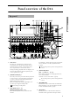
Panel overview of the D16 10 9 8 7 6 12 13 1415 11 16 17 30 31 32 2 23 3 24 25 26 18 19 20 21 27 22 28 4 5 * For the mic and trim controls etc., refer to the “Front panel” section. 1 LCD screen For channels 1–8 they adjust the pan of each channel. For channels 9–16 they adjust the balance. (→p.86) The D16 uses a TouchView system based on a touch panel screen. By pressing objects that are shown in the LCD screen, you can select pages, tabs, and parameters, and set their values.
sent. It is also used to specify EQ (for recording) for the analog inputs. You will also select this key when using the tuner. (→p.26, 75) 7 [EQ/PHASE] key This key is used to specify the EQ (for track playback) and phase of each channel. (→p.25, 78) These settings can be paired, and registered in a scene. 8 [INSERT EFFECT] key This key is used to select the location of an insert effect, to select the effect type, and to select and edit effect programs. (→p.
31 HDD access indicator restores the state prior to Undo. The previous 99 recording or editing operations can be undone. (→p.73) This key will light when the Undo function is available. This indicator will light when the internal hard disk is being accessed for recording, playback, or editing etc. 32 MIDI indicator 24 [TRIGGER] key 25 [SCRUB] key This is the on/off key for the Scrub, Play To/From, and Slow Play functions. These functions are used by operating the corresponding controller. (→p.
Unbalanced phone plugs can also be connected. 1 1: GND 2: HOT 3: COLD 2 1/4" TRS phone jack 3 If both your hands are occupied with playing an instrument etc., you can use a foot switch to perform basic operations of the D16’s recorder. The foot switch can be used to play/stop, start/ end manual punch recording, register a mark, and register tap tempo etc. (→p.
page. (→p.84) These jacks output the same audio signal as [PHONES]. These are RCA phono jacks. Rear panel [AC 9V] connector 8 Connect the included AC/AC power supply to this connector. This knob adjusts the volume level from the [MONITOR OUT L/R] jacks. [MIDI OUT] connector 9 MIDI messages are transmitted from this connector. Use this when you wish to control a connected external MIDI device from the D16. (→p.
Objects in the LCD screen and their functions e: Tab Objects in the LCD screen The LCD screen of the D16 features a TouchView system that uses a touch panel. By pressing objects that appear in the LCD screen, you can select pages, set parameter values, move the cursor, modify settings, and perform other operations. In this owner’s manual for the D16, words enclosed in “double quotation marks” such as “…”, “…” button, or “…” tab refer to items shown in the LCD screen.
1. Select the mode ● When you wish to access a function in the D16’s LCD screen, you must first press the appropriate key to select the Mode that contains that function. ● ● ● Directly press the parameter in the LCD screen. Press the up/down/left/right area of the [CURSOR] key to move to the parameter. In a list display screen, move by rotating the [VALUE] dial. Setting the parameter value The method of setting the parameter value will depend on the type of parameter.
Undo After recording or editing a track, you can execute Undo to return to the state before the data was recorded or edited. You can undo up to 99 previous operations. You can also use Redo to return the data to the state in which it was before you performed Undo. As an example, suppose that you have been using loop recording, and would like to select the best take. For details on loop recording, refer to p.72. 1 Press the [UNDO] key. The list will show the latest recording and previous recordings.
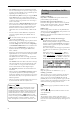
1. Connections If you will be monitoring through headphones, connect the 1/4" phone plug of your headphones to the [PHONES] jack. The diagram below shows a basic example of connections when using the D16 to record. Make the appropriate connections for your system, substituting your own equipment as necessary for the equipment shown here. The audio signal that is output from the [MONITOR OUT L/R] jacks and the [PHONE] jack is set in the [SOLO/MONITOR] “Monitor” tab page. (→p.
Connections for recording analog sources • Guitar, bass guitar ↔ [GUITAR IN] jack • Mic (XLR) ↔ [INPUT 1], [INPUT 2] jacks • Synthesizer etc. ↔ [INPUT 1]–[INPUT 8] jacks A guitar or bass guitar that is being sent through a compact effect device can be connected to [INPUT 1]–[INPUT 8]. When inputting in stereo, you should select two adjacent inputs (1–2, 3–4, 5–6, 7–8) so that track editing can be performed more efficiently.
Before turning off the power, turn the volume of all devices down to the minimum position, and turn off the power switches beginning with the devices that are at the end of the audio signal chain. Never disconnect the AC/AC power supply until the power is completely off. Data may be destroyed if you do so. The audio that is recorded on the D16 and the mixer settings etc. are saved automatically when you select or change songs, or when you turn off the power.
Step 2. Creating or selecting a song Creating or selecting a song [VALUE] dial to select the desired characters. In order to record a new song, you must first create a new song on the D16. Here’s how to create a new song, assign a name to the song, and select a song. 1. Creating a new song 1 Select the [SONG] “SelSong” tab page. Press the [SONG] key, and then the “SelSong” tab. The buttons in the LCD screen have the following function. “Space” button: Select a blank (space).
Basic operation Move the cursor to the song number, and rotate the [VALUE] dial Use this method to select a different song in the same drive. Creating or 1 Select the [SONG] “SelSong” tab page. Press the [SONG] key, and then the “SelSong” tab. 2 Press “SongNumber” (it will be highlighted), and rotate the [VALUE] dial to select the desired song number.
Step 3. Recording This section explains the basic recording procedures on the D16. Use the recording method that is appropriate for your purpose. During recording, the audio signal flows in the following order: input → mixer channel → recorder. 1. Selecting the input/record track The D16 has both analog and digital input jacks. In order to record an external audio source, the audio must be assigned to a mixer channel.
The ch.1 level meter will move to show changes in the input. 7 Audition the audio signal. • Select the [SOLO/MONITOR] “Monitor” tab page. • Press the “MasterLR” button to turn it “On” (highlighted). • Gradually raise the [PHONES LEVEL] knob or the [MONITOR OUT LEVEL] knob, and listen to the audio signal in your headphones or monitor system. Assign the keyboard connected to [INPUT 3] and [INPUT 4] to mixer channels 9 and 10 Basic operation 5 Check the record mode and input level, and audition the sound.
Digital input The D16 allows digital input and recording via its S/P DIF connector. As an example, we will explain how audio from a CD player connected to the [S/P DIF IN] jack can be input to mixer channels 1 and 2. S/P DIF IN 2. Adjusting the record level, and recording Here’s how to record the audio sources that you assigned to mixer channels in “1. Selecting the input/ record track” (→p.16). If you wish to create a new song and record it, refer to “1. Creating a new song” (→p.14). Turn [RHSL] off.
The D16 has sixteen tracks, and each of these tracks has eight virtual tracks. When recording solo parts etc., you can record each take on a different virtual track, and choose the best performance later. Or when using bounce (ping-pong) recording, you can specify an unselected virtual track as the recording destination, so that you can mix down sixteen tracks to two tracks without erasing any of the original track data. (→p.21) Recorded track Selected track 1 Select a virtual track.
7 Press the [STOP] key to stop playback. After you have finished recording, move the current time to a point earlier than the beginning of the recording, and check the newly recorded material. Manual punch-in/out using a foot switch You can use a foot switch (separately sold option) to switch between recording and playback. This allows you to switch between playback and recording while you play an instrument, or when you are at a distance from the D16. 1 Connect a foot switch to the [FOOT SWITCH] jack.
• 14 tracks of audio and two external audio input sources can be recorded on the remaining two tracks. • 16 tracks of audio can be overwritten onto two of these tracks. • 16 tracks of audio can be recorded on two currently unselected virtual tracks. If you use a CD-R/RW drive to create an audio CD, the data of tracks 1 and 2 will be written to the disc, so you will need to combine the completed song onto tracks 1 and 2.
• Set the “BounceMode” to “16Tr→2Tr.” 4 Specify the currently selected tracks for recording. Set “RecordVirtualTrack” to “Current.” 5 Adjust the pan of the playback tracks. Press the [PLAY] button to playback, and use the [PAN] and [BALANCE] knobs to adjust the stereo position of channels 1–16. 6 Adjust the playback/recording levels. Use the [CHANNEL] fader to adjust the playback levels and input levels. Use the [MASTER] fader to adjust the recording level.
Playback 1 Select the track(s) for playback. Press the [TRACK STATUS] keys for the tracks that you wish to play, to put them in PLAY mode (LED lit green). Using program playback 1 Select the [SONG] “PrgPlay” tab page. 2 Press the [PLAY] key to start playback. The songs will playback in the order of the list, starting from the first song in the program. During playback, you can press the [FF] key to advance to the next song.
Step 5. Changing the time location Here’s how you can change the time location within a song. Switching the counter display You can switch the units of the current time displayed by the counter. The following four displays can be selected. • ___, __, ___ “measures” , “beats” , “1/96th’s of a beat” • ___; __, ___ “minutes” ; “seconds” , “1/1000th’s of a second” • ___: __.__F “minutes” ; “seconds” . “1/30th’s of a second” • ___. __Free “minutes” , “seconds” (remaining recording time) The “___.
Adjusting the volume The input or recording/playback volume is adjusted by the [CHANNEL] faders. Raise or lower the faders to adjust the volume. (→p.86) The volume can be adjusted from silence (–∞) to unity gain (0 dB) to +12 dB gain. Normally, you should set the faders at unity gain (the position where the input signal is output at the same volume) and then lower the faders for any channels that are too loud, rather than raising the faders of channels that are too soft.
High EQ, Low EG • For the channel that you wish to adjust, select “High EQ Gain (H)” or “Low EQ Gain (L),” and rotate the [VALUE] dial to set the amount of gain. The value is displayed in the upper left of the screen. Mid EQ • For the channel that you wish to adjust, select “Mid EQ Cutoff Frequency (F),” and rotate the [VALUE] dial to set the cutoff frequency. The value is displayed in the upper left of the screen.
The values are displayed in the upper left. Basic operation Monitoring adjustments Here’s how to make settings for monitoring the sound from the D16. Normally, you will monitor the sound by connecting powered monitor speakers etc. to the [MONITOR OUT L/R] jacks, or by connecting headphones to the [PHONES] jack. Solo settings Selecting the signal to be monitored 1 Select the signal to be monitored. • Make your selection in the [SOLO/MONITOR] “Monitor” tab page. • Normally you will select “MasterLR.
Registering/recalling a scene The mixer settings you adjust can be registered as a scene, and scenes can be automatically recalled as time passes during playback. Scenes can also be recalled as general-purpose settings, and mixer settings you recalled can be copied to a different time location, or re-adjusted and then overwritten elsewhere. Up to 100 scenes can be registered in each song. The following contents can be registered as a scene.
Overview of the effects The D16 provides a maximum of eight insert effects that can be inserted into an analog input or mixer channel, two master effects that are applied to a send signal from each channel, and one final effect that is applied to the master LR output. All these effects are independent of each other. This means that you can use a maximum of eleven effect programs simultaneously.
1in1outx4 (mono-in/mono-out × 4) • While recording four vocals simultaneously, you could apply Exciter-Comp to voices that lack impact, and apply Limiter-P4EQ to loud voices as you record. 1in1outx8 (mono-in/mono-out × 8) • Comp, Limiter, Gate, or Expander could be applied to individual recorded tracks to adjust the dynamics, or Chorus, Phaser, or Delay could be applied. Other examples are shown below.
Master effects The D16 contains two master effects (MstEff1 and MstEff2) which can be used simultaneously. You can adjust the send amount from each channel to change the depth of the effect (→diagram on following page). Applying an insert effect to a track during playback How the master effects can be used Here’s how you can insert an insert effect into a mixer channel so that the effect is applied to the track playback. The master effects are used mainly for spatial processing (reverb etc.
Final effect One stereo-in stereo-out effect is provided as the final effect. It applies to the master LR output. Editing an effect You can edit (modify) the effect programs that are used as insert effects, master effects, and final effects. If you select a different “EffectNumber” or turn off the power without saving, the effect settings you edited will be lost. If you wish to keep your edited settings, you must save them after you are finished editing.
You can use an expression pedal or MIDI controller to control an insert effect in realtime. 7 Assign a name to the effect program that you edited. • Press the “Rename” button to access the “RenameEffect” dialog box. For the rename procedure, refer to “2. Naming a song” (→p.14). • After you have assigned a name, press the “OK” button. 8 Store the effect program. • If the D16 is playing, press the [STOP] key to stop playback. • Playback “Store” button to access the “StoreEffect” dialog box.
• Press the “Cntrl Icon” button to access the “ControlDevice” dialog box. Using an external effect A send signal can be output from the [AUX OUT] jack, and processed by an external effect. The output of the external effect can then be returned to the [INPUT 1]– [INPUT 8] jacks and sent to the desired channels or to the master LR bus. • Select “Param,” and rotate the [VALUE] dial to select the parameter that you wish to control.
You can use mixer settings such as EQ, faders, and effects to adjust the audio from each recorded track in order to create a finished song (→p.25, 29), and record the final result on a two-channel recorder (DAT recorder, MD recorder, cassette recorder etc.). This process is called mixdown. • Turn “Off” the “M (mute)” button for the connected input. • Press the “Fader” icon and rotate the [VALUE] dial to raise the value so that the audio signal will be input.
Step 9. Track editing On the D16, tracks can be edited in the following ways. For the procedures, refer to p.37, 53 and p.56. If there is little remaining free space on the hard disk, it may not be possible to perform track editing. You will need to create enough free space for track editing (the time between IN-OUT or TOEND). Copying track data: Copy Track The Copy Track command copies recorded track data from the specified region (IN–OUT) to another location (TO).
How the editing commands use the IN, OUT, TO, and END times Basic operation Copying an entire track/Copying to a V-track: Copy Whole Track This command copies an entire recorded track (from beginning to end) to a different entire track. IN OUT TO Copy Track • You can copy not only one track, but multiple tracks simultaneously.
Step 10. Song editing On the D16, songs can be edited in the following ways. Undo is not available for song editing. Copying a song: Copy Song Song editing procedure Here is the basic procedure for song editing operations. For actual examples, refer to p.61. This command copies the currently selected song to a song number in any drive. • You can use this to save a backup of your song on a different hard disk drive etc.
Playing rhythms Specifying and playing a rhythm ● Select the [TEMPO/RHYTHM] “SetUp” tab page. The settings described below are made in this page. When you enter this page, a rhythm will sound. To silence it, press the “Mute” button. ● Press “SelRhythm,” and rotate the [VALUE] dial to select the desired rhythm pattern. Recording your performance while you listen to the rhythm You can record your performance while listening to the built-in rhythm as a guide.
5 Check the record mode, input level, and audio. Refer to “Assign the guitar input from [GUITAR IN] to mixer channel 1,” steps 5, 6, and 7. (→p.16) After checking the settings, press the [STOP] key to stop. 6 Adjust the recording level, and record. Refer to “2. Adjusting the record level, and recording” (→p.18). Setting the tempo A song on the D16 can be controlled by the following tempo sources.
Tempo track The tempo track records MIDI clock data from an external MIDI sequencer etc., or tap tempo. Recording MIDI clock data from an external MIDI sequencer, and using it as the tempo track • Select the tempo in “Tempo,” the time signature in “Beat,” and the rhythm pattern in “Rhythm.” For tempo map “001” it is not possible to change “Meas.” • When you have finished making settings, press the “OK” button.
If MIDI clock messages are not being transmitted correctly from the MIDI sequencer, tempo recording may end prematurely. Recording tap tempo While playing back a song, you can press (tap) the [PLAY] key at the beginning of each measure or beat to record a tempo. Alternatively, you can use a foot switch (separately sold option) instead of the [PLAY] key. Tap tempo can be used to record the tempo after you have recorded a song.
A word about data There is always a remote possibility that the D16 will malfunction, causing errors in the data or loss of data. If the D16 malfunctions, recorded data or other types of data may be lost. Please copy or back up your important data on an external drive such as a hard disk or removable disk. that were used by that song, the modified effect settings will be used the next time you play the copied song, meaning that it will not sound the same.
Restore The Restore command will recall the backed-up data so that it can be used on the D16. When restoring data of all songs (“BackupAllSongs”) or one song (“Backup1Song”), you can select whether or not you wish to overwrite the current user effect data. It is also possible to restore a specific individual song from the songs that were backed up by “BackupAllSongs.” Backup and restore commands are performed in the [SYSTEM] “B–U/Rst” tab page. For the procedure, refer to p.50.
Counter: Counter display The counter located in the upper right of each page shows the current location of the recorder. Use the following procedure to switch the counter display. Reference SYSTEM 2. SYSTEM P1 Control: Foot switch/control change device (pedal/MIDI) settings From the left, the numbers are Minutes : Seconds. Milliseconds (1/1000 second). ___:__.__F (MSF): The current location will be shown as an absolute time from the beginning of the song.
MIDI OUT of your external MIDI device to the [MIDI IN] connector on the rear panel, and transmit the selected MIDI data to control the effect. CC(Control Change) #000…119: MIDI control change messages can be used to control the effect. Connect the MIDI OUT of your external MIDI device to the [MIDI IN] connector on the rear panel, and transmit the selected MIDI control change message to control the effect. 4. Ass(CtrlChgAssign) ............
Select the type of synchronization data that will be transmitted from the [MIDI OUT] connector. MTC30 (MTC30: On): MTC30NDF (MIDI Time Code 30 non-drop frame) will be transmitted. Reference P4 DiskUtil: Initializing/ formatting/checking a drive Here you can initialize, format, and check a drive. MIDIClock (MIDI Clock: On): MIDI Clock will be transmitted. Off (Gen: Off): Synchronization data will not be transmitted.
4. SelOperation ................[EjectRMD, CheckDrive, Initialize, Format, LoadSystem] Select the operation that you wish to perform on the drive. If you press the “ ” button, you will be able to select from a list. EjectRMD: The removable disk selected by “Drive ID” (P4-1) will be ejected. If the currently selected song is on the removable disk, it will be locked from the D16, so you should use this operation to eject it. In other cases, you can use the eject button of the drive to eject the disk. (→p.
Exchanging removable disks Reference BackupUserData: Back up user effect data. 1 If the currently selected song is on a removable disk, use the following procedure to exchange disks. 1 Select the [SYSTEM] “DiskUtil” tab page. 2 Use “SelOperation” to select “EjectRMD.” 3 Press the “Exec.” button. The disk will be ejected, and the internal drive will be selected. Insert a different disk into the removable disk drive. If you will be using it for recording/playback, reselect that drive.
*1: For “Backup1Song” or “BackupAllSongs” (“B– U/RstType”), this displays the backup destination drive, drive information (“RMD----”), and the number of media volumes required (“x1”– “x99”). *2: For “BackupUserData” (“B–U/RstType”), this displays the backup destination drive and user effect “---”. *3: For “Restore” (“B–U/RstType”), this displays the restore destination drive, and lets you select the song number. The currently selected drive will be the restore destination.
Reference 3. RECORD SYSTEM 1 Use the [SONG] “SelSong” tab page or the [SYSTEM] “DiskUtil” tab page to select the restore destination drive. 2 Select the restore operation. In the [SYSTEM] “B–U/Rst” tab page, select “Restore” for “B–U/RstType.” 3 Select the restore source drive (“Source”). Press the “Drive” button to access the dialog box, select the drive, and press the “OK” button. 4 Select the restore source song (“Source”).
16Tr→2Tr: Select this when recording 16 tracks of playback onto two tracks or one track. The track playback will be valid for the channel(s) whose [TRACK STATUS] key is set to REC (LED lit red), and will be recorded together with the other playback tracks. Be aware that if rhythm is “On” during bounce recording, the rhythm will also be recorded together with the other sounds. 4. TRACK P1 Vtr1–8: Select virtual tracks 1–8 2 2. RecordVirtualTrack ....................
Reference OUT IN P3 EditTrk: Track editing DestTrack DestTrack 7 6 3 Blank EraseTrk: This operation erases the track data in the IN–OUT range of the erase destination track (“DestTrack”). 4 Editing will apply to currently selected tracks 1–16 (→”Vtr1–8,” “Vtr9–16”). Virtual tracks that are not selected will not be affected by editing. (However, “CopyWholeTrk” and “SwapWholeTrk” are exceptions.) When this is executed (“Exec”), the IN–OUT range will contain silence.
OUT IN When this is executed (“Exec”), the expansion/ compression destination track will be overwritten. SourceTrack A The available ratio of expansion/compression is limited, and if the IN–OUT duration is drastically different than the TO–END duration, an error message will appear when this is executed. In general, the TO–END time can be changed to 50–200% of the IN–OUT time.
For “CopyWholeTrk” (“EditType”), select the copy destination track. DestVTrack (a...h) For “SwapWholeTrk” (“EditType”), select the swap destination track. SourceTrack For “ReverseTrk” (“EditType”), select the reverse copy destination. 2. SourceTrack ....................[1…16, 1–2…15–16, 1–4…13–16, 1–8, 9–16, 1–16, Clip#*1] [1…16, 1–2…15–16] *2 Select the source track for the editing operation. 4. Times...................................................
For “ExpCmpTrk” (“EditType”), this will appear when you press the “Mode” button. 8a 8b 8a. SelectExpCmpMode............[Fast, Mid, Best] Select the conversion mode for expansion/compression. Fast: Emphasize processing speed Mid: Between “Fast” and “Best” Best: Emphasize audio quality If “SelectPitch” (8b) is “Variable,” this setting will have no effect. 8b. SelectPitch.........................[Fixed, Variable] Select whether or not the pitch will change as a result of the expansion/compression.
“DeleteTrk” Here’s how the IN–OUT range of track 1 can be deleted. 1 Set the IN and OUT time locations. (→p.70) 2 Select delete. In the [TRACK] “EditTrk” tab page, set “EditType” to “DeleteTrk.” 3 Select the track number from which data will be deleted. Set “DestTrack” to track “1.” 4 Execute the delete operation. Press the “Exec.” button. The display will ask “AreYouSure?” Press the “Yes” button to delete the data. When the data has been deleted, the display will indicate “Completed.
4 Select the expansion/compression source track number. Set “SourceTrack” to track “1.” 5 Select the expansion/compression destination track number. Set “DestTrack” to track “2.” 6 Specify the number of times that the data will be copied. Set “Times” to “3.” 7 Execute the expansion/compression operation. Press the “Exec.” button. The display will ask “AreYouSure?” Press the “Yes” button to reverse the data. When the data has been expanded/compressed, the display will indicate “Completed.
Reference 3. Rename .......................................................... 5. SONG Press the “Rename” button to access the dialog box, and modify the song name. You can input a song name of up to sixteen characters. (→p.14) 1 2 3 4 4. New ............................................................... This creates a new song following the last song of the currently selected drive. 1. SongNumber ........................ [I…G/001…100] Press the “New” button to access the dialog box.
1. EditType....................... [CopySong, MoveSong, DeleteSong, ProtectSong, CopyAllSongs] Select the song editing operation. Press the “ ” button, and you will be able to select an editing operation from the following dialog box. 2. SourceSong........................... (I…G/001…100) This indicates the edit source song. The currently selected drive and song will be displayed as the edit source. For “CopySong” (“EditType”), the copy source drive and song number will be displayed.
For “ProtectSong” (“EditType”), this protects the song. Each time you press the “Exec.” button, the setting will alternate on/off. For “CopyAllSongs” (“EditType”), this executes the copy operation. When this is executed, the songs will be copied following the last song on the copy destination drive (“DestSong”). They will not be overwritten. 6. Protect On/Off Mark..........................
P3 PrgPlay: Program playback of songs P4 CDR/RW: Creating and playing a CD-R/RW You can create a program play list to arrange songs in a desired order, and play them consecutively. The D16 allows you to connect a CD-R (CD Recordable) or CD-RW (CD Re-Writable) drive and produce an audio CD. For settings and playback procedure, refer to p.23. 1 2 3 The first through last events of tracks 1 and 2 of the currently selected song will be written to the CD-R/RW.
4. WriteToCD ...................................................... This executes the writing operation to the CD-R/ RW. 5. CD.................................[Abs–Song, Abs–Total] Select the display method for the CD-R/RW playback counter. Abs–Song: Display the elapsed time for a single song. Abs–Total: Display the elapsed time for the entire disc. 6. CD-R/RW transport keys Use these keys to play, stop, and select songs on an audio CD you created.
3a. SelectAll.......................................[On, Off] 6. STORE Select all marks for deletion. You can store a time location for registration to a locate memory, scene, or mark. The time at which you pressed the [STORE] key is remembered, and can be registered by pressing one of the registration destination keys. If you press the [STORE] key once again instead of pressing a registration destination key, the store operation will be cancelled.
Reference The following settings can be registered in a scene. MixerChannel Eq, EffectSend1, 2, AuxSend, Pan/Balance, ChFader, PairOn/Off InsertEffect Assign, EffectType, InsertTo, EffectNumber MasterEffect EffectNumber, EffectReturn FinalEffect EffectNumber Filters are provided for each of these parameter groups, allowing you to select whether or not they will be registered or recalled (→”Filter”). The “MixerChannel” parameters are enabled for each selected channel.
You can either directly press the time value that you wish to modify, or use the cursor to select it. Then use the [VALUE] dial to modify the time. Press the “OK” button to finalize the change, or press “Cancel” button to cancel the change. Automatically switching scenes while the song plays Here’s how to make scenes switch automatically during playback when their registered times arrive.
Here’s how to delete an unwanted scene. Undo is not available for this operation. Please use caution. 1 Select the scene. As described in the procedure for “Recalling a scene,” recall the scene that you wish to delete. 2 Delete the scene. In the [SCENE] “ReadDel” tab page, press the “Delete” button. Check the “Delete scene number” in the upper left, and if you are sure that you want to delete it, press the “Yes” button. To cancel without deleting, press the “No” button.
“TempoMap” and “TempoTrack,” this will show the time signature corresponding to the current time as specified in the “TmpMap” tab page. 9. TEMPO/RHYTHM Here you can make tempo, time signature, and rhythm (metronome) settings for a song. When the counter is displaying “MBT” (measures, beats, and 1/96th of a beat) (→p.45), it will operate according to the specified tempo. 4. SelRhythm.......................
This is the number of the selected tempo map. At the right, the display shows the starting measure, tempo, time signature, and rhythm pattern of this tempo map. When “TempoSource” (→P1-1) is “Manual,” it is not possible to select “TempoMap.” 2. New ............................................................... When you enter this page, the rhythm will sound regardless of the “Rhythm” “On/Off” setting, allowing you to set the tempo and rhythm. However, you can use this button to mute the rhythm. (→p.
Start of deleted region for “Delete Track” Start time of swap source and swap destination for “Swap Track” Start of reversed region for “Reverse Track” Start of expanded/compressed region for “ExpCmpTrack” 10. IN/LOC1, OUT/LOC2, TO/LOC3, END/LOC4 If locations in the song have been registered to the [IN/ LOC1], [OUT/LOC2], [TO/LOC3], and [END/LOC4] keys, you can use them to perform the following functions.
Reference 11. AUTO PUNCH 4a P1 AtPunch: Settings for auto punch-in/out recording 4c 4a. PreRoll .........................................[00…10] Auto punch-in/out recording is a function that automatically starts recording (punch-in) and stops recording (punch-out) at the time locations you specify beforehand. Set the pre-roll time. 4b. PostRoll........................................[00…10] Set the post-roll time.
Loop recording procedure 12. LOOP P1 Loop: Loop playback/recording settings This function repeatedly plays/records over the range of time specified by [IN/LOC1]–[OUT/LOC2]. 1 4 3 2 1. Loop..................................................[On, Off] Turn loop playback on/off. On: Playback will occur repeatedly over the IN–OUT range. When “On,” the [LOOP] key will light. Off: Playback will be normal. 2. In ............................................(000:00.000…) This shows the loop start time.
Reference 13. UNDO 14. TRIGGER Trigger Recording is a function that automatically initiates (triggers) recording when the input volume exceeds a specified level. 2 1 3 4 1. UndoList ............................. [Level 00, 01…99] P1 Trigger: Settings to start trigger recording 1 You can select the operation that will be undone. By selecting “01”–“99” (the number of prior operations executed) and executing Undo, you can return to the state before the operation was executed.
This setting is not valid for the beginning of the song. Also, if you use trigger recording to continue recording after the end of a previously-recorded track, setting other than “000 ms” will cause a corresponding length of the previously-recorded sound to be lost. Trigger on Threshold 15. SCRUB Scrub, Play From/Play To, and Slow Play functions can be switched on/off here. Each time you press the [SCRUB] key, the setting will be switched on or off.
Reference 2. TrackSelect...................................... [Trk1…16] 17. INPUT Select the track that will be played and whose waveform will be displayed. Press the “ ” button and select from the list. : Expand the waveform display vertically. : Shrink the waveform display vertically. : Expand the waveform display horizontally. : Shrink the waveform display horizontally. P1 Ch1–8: Select the inputs for mixer channels 1–8 Here you can select the inputs for mixer channels 1–8.
These inputs are sent via the stereo/mono switch through the balance and fader settings, and then to the master LR bus. Use the [AUX OUT] jack to transmit the effect send to your external effect processor. (→p.82 [MASTER EFFECT/AUX] “AuxSend” tab page) 3a. Stereo/Mono ...................... [Stereo, Mono] Stereo: Odd-numbered channel inputs will be sent to the master L bus, and even-numbered channel inputs will be sent to the master R bus.
P4 InEq5–8: EQ settings for inputs 5–8 Here you can apply EQ (equalizer) to the analog inputs from the [INPUT 5]–[INPUT 8] jacks. Refer to “P3 InEq1–4: EQ settings for inputs 1–4.” P5 Tuner: Tuner You can use the built-in tuner to tune an instrument connected to the [INPUT 1/GUITAR IN] jack or input from the built-in mic. You can also measure the pitch of a track. Recording is not possible while this page is displayed. Nor is it possible to select this page during recording or playback.
18. EQ/PHASE P3 Eq9–16: EQ settings for mixer channels 9–16 Here you can apply EQ (equalizer) to the playback of tracks 9–16. Refer to “P1 Eq1–4: EQ settings for mixer channels 1– 4.” P1 Eq1–4: EQ settings for mixer channels 1–4 Here you can apply EQ (equalizer) to the playback of tracks 1–4. Use these settings when you wish to apply EQ to the playback. P4 Phase: Phase settings for mixer channels The EQ has three bands.
Select the location at which the insert effect will be inserted. The insert effects can be applied to the analog inputs during recording, or to track playback. Press the “ ” button to access the dialog box and make settings. Press the “OK” button to execute your settings, or press the “Cancel” button to cancel them. The D16 lets you use up to eight different insert effects simultaneously. Insert effects cannot be used if “DigiIn” is turned “On” in the [INPUT] “Ch1–8” or “Ch9–16” tab pages.
3b. Effect On/Off...............................[On, Off] P2 InsEff1: Selection and settings for Insert Effect 1 Turn each effect on/off. On: The effect is on. Off: The effect is off. 4 5 6 1 2 3 4. Bypass............................................................ This lets you compare the sound processed by the effect with the unprocessed effect. Press the “Bypass” button to bypass the effect (the unprocessed sound will be heard). 1. InputLevelMeter...............................................
Reference 20. MASTER EFFECT/AUX/ FINAL EFFECT P3 InsEff2: Selection and settings for Insert Effect 2 Select insert effect 2 and make settings for it. For details refer to “P2 InsEff1: Selection and settings for Insert Effect 1.” The master effects are used by sending an adjustable send amount from each channel to the effect. They can be used to adjust the overall depth and balance. The D16 provides two master effects. The final effect is used to adjust the final stage of the master LR bus.
5. RetBal...................................[L63…CNT…R63] Adjust the return balance from the master effect to the master LR bus. “L” and “R” indicate L (left) and R (right) of the master bus. 6. Bypass............................................................ Refer to “Bypass” for the insert effects (→p.80). P3 EffSnd1: Send settings for effect 1 Here you can set the send amount from each mixer channel to effect 1. 7. Rename ..........................................................
Set the send amount from each mixer channel to the [AUX OUT] jack. 3. Pair ................................................................ Specify pairing for adjacent mixer channels. (→p.76 ”Pair”) Select the effect program whose name you wish to modify, press the “Rename” button to access the dialog box, and modify the name. A name of up to 16 characters can be input. (→p.14) 6. Store ..............................................................
21. SOLO/MONITOR P2 Monitor: Monitor settings Select the audio signals that will be output from the monitor output ([MONITOR OUT L/R] jacks) and the headphone output ([PHONES] jack). P1 Solo: Solo select 3 2 1 1 4 3 2 1. SelectSolo .......................[1…8, 9–10…15–16, S1, S2, A1, R1, R2/On, Off] 1. SelectMonitor ..................................................
Reference 3. RhythmLevel ..................................[000…100] Adjust the level at which the rhythm will be monitored. It will be output directly at this volume. 4. AutoIn ...............................................[On, Off] For mixer channels whose [TRACK STATUS] is set to REC, you can specify whether to monitor the external input ([INPUT 1/GUITAR IN]–[INPUT8], [S/P DIF IN] jacks) or to monitor the track playback sound. This selection applies to the “SelectMonitor” settings “MasterLR” and “Cue.
This setting applies to the level meters of this page. Press the “PkHold” button to access the dialog box, and make the desired setting. Press the “OK” button to activate your selection, or press the “Cancel” button to cancel. 0…8s: 0–8 seconds ∞: The peak hold indicator will be held forever. The hold indicator will be cleared when you press the “PkHold” button to access the dialog box. 25. FADER Adjust the volume levels.
26. TRANSPORT KEYS These keys are used to operate the recorder for operations such as recording and playback. 5 Reference start recording, the monitor output will behave in the same way as when actually recording, allowing you to practice recording. It is convenient to use this to rehearse before using auto punch-in/out recording. 6 4 3 2 1 1. [FF] key When stopped or playing, this key moves the time backward (rewind).
88
Effect Parameter List *Time (Reverb Time [sec]) ..................................01...10.0s Sets the reverberation time * Parameters marked by an “*” in front of the screen parameter name can be controlled by an external device such as an expression pedal. (→p.45 “Device”) 6: RV6: Bright Room This room-type reverb emphasizes the early reflections that make the sound brighter. Time (Reverb Time [sec]) ............. 0.1...3.0s Sets the reverberation time HiDamp (High Damp [%]) .................0...
HiDamp (High Damp [%]) ................. 0...100 Sets the damping amount in the high range LoDamp (Low Damp [%]) ................. 0...100 Sets the damping amount in the low range Spread (Spread) ................................. 0...50 Sets the width of the stereo image of the effect sound Mix (Wet/Dry).............. Dry, 1:99...99:1, Wet Sets the balance between the effect and dry sounds : High Damp [%], : Low Damp [%] These parameters set the damping amount of high range and low range.
The “Attack” and “Release” parameters specify attack time and release time of delay level control. Phase (LFO Phase [degree])....–180...+180 Sets the LFO phase difference between the left and right *Speed (LFO Frequency [Hz]). 0.02...20.0Hz Sets the LFO speed This stereo delay effect pans the delay sound left and right using the LFO. LTime (L Delay Time [msec])....... 0...680ms Sets the delay time for the left channel LFback (L Feedback)................ –100...
18: MO5: St.Tremolo (Stereo Tremolo) This effect modulates the volume level of the input signal. The effect is stereo, and offsetting the LFO of the left and right phases from each other produces a tremolo effect between left and right. LFO (LFO Waveform) ..... TRI, SIN, Vintage, Selects LFO Waveform Up, Down Shape (LFO Shape) .................–100...+100 Determines how much the LFO waveform is changed Phase (LFO Phase [degree])....–180...
: Attack, : Release These parameters set the attack time and release time. A higher attack time will cause the compression to be applied more slowly. : Side PEQ Insert, : Side PEQ Cutoff [Hz], : Q, : Gain [dB] These parameters are used to set the EQ applied to the trigger signal. The Limiter determines whether the compression is applied or not, based on the post-EQ trigger signal. Setting the equalizer allows you to set the Limiter to respond to any frequency band.
If you set the “Sampling Frequency” to about “3kHz” and set “Pre LPF” to “Off,” you can create a sound like a ring modulator. *Pitch (Pitch Depth) ............................0...100 Sets the pitch variation of the moving sound : Resolution, : Output Level If you set a smaller value for the “Resolution” parameter, the sound may be distorted. The volume level may also be changed. Use “Output Level” to adjust the level. *Pan (Pan Depth) .......................–100...
Insert (2in2outx2), Final These algorithms can be selected for an insert effect if “2in2outx2” is selected for “Select Eff Type”. They can also be selected for a final effect. Respo (Response)............................0...100 Sets the speed of the response to the modulator input NLevel (Noise Level).........................0...100 Sets the noise mix level to the Carrier LoGain (Low Gain [dB]) ................–12...+12 Sets the low-range output level of the vocoder HiGain (High Gain [dB])................
EQTrim (EQ Trim) ............................. 0...100 Sets the input level of EQ applied to the effect sound LEQG (Pre LEQ Gain [dB]) ....–15.0...+15.0 Sets the gain of Low EQ HEQG (Pre HEQ Gain [dB]) ...–15.0...+15.0 Sets the gain of High EQ Mix (Wet/Dry).............. Dry, 1:99...
Comp (Compressor/Limiter) Category: Pre-amp simulator 48: PA1: Pre Amp Simulator [Dist, NR, Tone, AmpSim] EB1 – EB3 Category: Bass multi 49: EB1: Bass Multi1 [Comp, Exctr, P4EQ, Cho/Fl, S.Dly] Ratio (Ratio) ..................1.0:1...50.0:1, Inf:1 Sets the signal compression ratio Thrshl (Threshold [dB])................ –40...0dB Sets the level above which the compressor is applied Attck (Attack) ....................................1...100 Sets the attack time Relse (Release)..............................
AmpSim (AmpSimulator) This effect simulates the acoustical characteristics of a guitar amp. Even if you are recording your instrument via a direct line, you can produce a realistic sound as though a guitar amp were actually being used. Type (Amplifier Type) .................... AMP1...5 Selects the type of guitar amplifier CabRes (CabinetResonator) This effect simulates the acoustical characteristics and cabinet resonances of a guitar amp speaker cabinet.
Mic Simulator is an effect that converts sounds recorded on a conventional dynamic mic so that they appear to have been recorded on an expensive condenser mic, a special studio mic, or a vintage mic. InMic (Input Mic Type) ............Vo.Dy, Mlt.Dy Selects the mic that was used for recording OutMic (Output Mic Type).... Vnt.Dy, Mlt.Cn, Selects the mic to be simulated Pc.Cn, Whale, Vo.Cn, Vo.Tb, BDr.Dy Set (Setting) .................. Close, On, Off, Far Mic setting Trim (Trim) ..............................
68: MM14: Exciter – Limiter [Excit2, Limitr] 69: MM15: Exciter – Cho/Flng [Excit2, ChFl1] 70: MM16: Exciter – Phaser [Excit2, Phaser] Effects within multi-effect programs MM1–MM33, and their parameters Here are explanations of the parameters of each effect in the multi-effect chains listed above. P4EQ (Parametric 4band EQ) Trim (Trim).........................................0...100 Sets the parametric EQ input level 71: MM17: Exciter – Mt.Delay [Excit2, Mt.Dly] Fc1 (Band1 Cutoff [Hz]) .............20.
Trim (EQ Trim) .................................. 0...100 Sets the EQ input level HEQG (Pre LEQ Gain [dB])......–15...+15dB Sets the gain of Low EQ LEQG (Pre HEQ Gain [dB])......–15...+15dB Sets the gain of High EQ Limitr (Limiter) Mix (Wet/Dry).................. –Wet...–1:99, Dry, Sets the effect balance of the chorus/ 1:99...Wet flanger Phaser *Speed (LFO Frequency [Hz]). 0.02...20.0Hz Sets the LFO speed Ratio (Ratio) .................. 1.0:1...50.
Insert (1in1outx8) These algorithms can be selected as an insert effect if “1in1outx8” is selected for “SelectEffType.” Different insert effects can be used on each of eight channels/ tracks. Thrshl (Threshold) ............................0...127 Sets the level at which the effect begins to apply Ratio (Ratio)...............................1.0:1...inf:1 Specifies the compression ratio Attack (Attack)...................................1...100 Specifies the length of the attack Relse (Release) ..............
Appendices Troubleshooting sampling rate converter inside the D16 will require two or three seconds to follow this frequency change. Please wait until the sound can be heard once again. ■ Is the format of the digital input inappropriate? ■ Has the [TRACK STATUS] been set to MUTE? (→p.86) ■ Has Solo been turned on to mute the track audio? (→p.
Can’t record ■ Is the [CHANNEL] fader of the D16 lowered? (When the [RECORD] “RecMode” tab page item “Select RecMode” is set to “Input”) ■ Is the [MASTER] fader of the D16 lowered? (When the [RECORD] “RecMode” tab page item “Select RecMode” is set to “Bounce”) • Master/final effect: While watching the meter in the [MASTER EFFECT/AUX] “EffSnd1,” “EffSnd2,” or “FinalEff” tab page, adjust the effect parameters so that “CLP” does not light.
■ Is the external effect send set to 0 or near 0? → In the [MASTER EFFECT/AUX] “AuxSend” tab page, use “Aux” to raise the external send level. ■ Is the output of the external effect connected to the [INPUT 1]–[INPUT ] jacks and assigned to a mixer channel? → Use [INPUT] “Ch1–8” or “Ch9–16” to assign the input. ■ Are the sub input settings correct? (→p.
Messages External disk drive The external disk drive is not recognized in the [SYSTEM] “DiskUtil” tab page ■ Is the external disk connected correctly? (→p.48) ■ Are two or more disk drives set to the same SCSI device ID? → For details on setting the SCSI device ID, refer to the owner’s manual of your drive. Confirmation messages Completed ■ The operation has been completed successfully. Please press the “OK” button.
DriveProtected TempoSlow disk) is write protected. → Remove the disk, and turn off write protection. recorded correctly. → If you are recording MIDI clock, set the tempo of the MIDI transmitting device (sequencer etc.) to a setting of =40 or faster. → If you are recording tap tempo, please tap at a slightly faster tempo. the selected drive.
D16 specifications Operating temperature +5 — +40 degrees C (do not allow range: condensation) ■ Specifications Number of tracks: 128 tracks (including virtual tracks) 16 tracks simultaneous playback, 8 tracks simultaneous recording @ 16 bits 8 tracks simultaneous playback, 4 tracks simultaneous recording @ 24 bits Recording format: 24 bit/16 bit uncompressed, 44.1 kHz Recording time: 16 bit recording: maximum 6.5 hours 24 bit recording: maximum 3.3 hours * When internal 2.
Connector: Format: Connectors: D-sub 25 pin female SCSI-2 compatible DIN 5 pin × 2 Connector: 1/4" phone jack (use separately sold PS-1) Connector: 1/4" stereo phone jack (use separately sold XVP-10 or EXP-2) ■ Accessories ■ Options DIN 4 pin :AC/AC power supply (Use the included AC/AC power supply) Appendices Connector: :PS-1 pedal switch :XVP-10 EXP/VOL pedal :EXP-2 foot controller D16 * Appearance and specifications of this produ
[ Digital Recording Studio ] D16 MIDI Implementation Chart MIDI implementation chart Model Function Transmitted Recognized Basic Channel Default Changed × × × × Mode Memorized Messages Altered × × × × *********** True Voice *********** Date : 1999. 9.
Block diagram MIDI Appendices Block diagram 111
Effect Program List INSERT EFFECT Preset128 User128 ProgNo Categ ProgramName Reverb 7 I001 RV1 ReverbHall I002 RV2 SmoothHall I003 RV3 WetPlate I004 RV4 DryPlate I005 RV5 ReverbRoom I006 RV6 BrightRoom I007 RV7 ER Delay 6 I008 DL1 L/C/R Delay I009 DL2 St/X.Delay I010 DL3 St.MtapDelay I011 DL4 St.ModDelay I012 DL5 St.DynaDelay I013 DL6 AutoPanDelay Modulation 7 I014 MO1 St.Chorus I015 MO2 St.Flanger I016 NO3 St.Phaser I017 MO4 St.Vibrato I018 MO5 St.Tremolo I019 MO6 St.
MASTER EFFECT Preset32 User32 FINAL EFFECT Preset32 User32 ProgNo Categ ProgramName Reverb 15 M001 RV1 ReverbHall M002 RV2 SmoothHall M003 RV3 WetPlate M004 RV4 DryPlate M005 RV5 ReverbRoom M006 RV6 BrightRoom M007 RV7 ER M008 RV3 DarkPlate M009 RV4 BrightPlate M010 RV1 ARENA M011 RV2 Cathedral M012 RV5 Club M013 RV6 ListenigRoom M014 RV7 NeoAcoustic M015 RV6 Garage Delay 6 M016 DL1 L/C/R Delay M017 DL2 St/X.Delay M018 DL3 St.MtapDelay M019 DL4 St.ModDelay M020 DL5 St.
Rhythm Name List (215patterns) For Beat settings other than 3/4, 4/4 or 6/8, only (Blank), Metro, or Hihat can be selected. For Beat settings of 3/4, 4/4 or 6/8, the following rhythm patterns can be selected in addition to (Blank), Metro, or Hihat. [I], [F], and [E] indicate Intro, Fill, and Ending pattern marks. In this list, Length and Tempo values are the number of measures in each rhythm, and the recommended tempo.
Demo Song List 1. Alone 2. Clarity 3. Someday All songs written and performed by Michael Blake Drums by Paul Roraback Demo Song Rhythm Pattern Appendices ©1999 Michael Blake -all rights reserved.
Index Numerics 16Bit/16Track 59 1in1outx4 29, 79 1in1outx8 29, 79 1in2outx2 29, 79 24Bit/8Track 59 2in2outx2 29, 79 A Analog 16, 75 Applying an insert effect to a track during playback 31 Applying the insert effects while you record 30 Assign a name to the effect program 33, 80, 82, 83 Audio CD 21 Audio events 85 Auto punch-in/out 20, 71 Auto save function 43 AutoIn 85 Automatic switching scenes 66 AuxSend 34, 81, 82 B Backup 43, 49 Backup procedure 50 BALANCE 25, 86 Bass multi 97 Bounce recording 51 Boun
S Pair 26, 76, 86 PAN 25, 86 Peak hold 85 Phase 78 Pingpong recording 51 Pitch 56 PLAY 86 Play 74 Play From 74 PLAY key 87 Play To 74 Polarity of the foot switch 45 Popup button 8, 9 Post-fader level 85 Post-fader level meter 85 Post-roll 71 Power on/off 12, 48 Pre -fader level meter 85 Pre-amp simulator 97 Pre-fader level 85 Pre-roll 71 Preset 29 Program play 23, 62 Punch-in 19 Punching-in/out re-recording a specific area 19 Punch-out 19 Scene 28, 65 copy 66 delete 67 editing and overwriting 66 Filtering