E 1
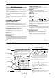
Parameters in the LCD display screen “ ” Parameters displayed in the LCD screen are enclosed in double quotation marks “ ”. About this manual This “Parameter Guide” contains explanations and other information regarding the operations of the parameters and settings on the TRITON STUDIO. The explanations are organized by mode, and page. Explanations and other information on the effects and their parameters are also provided for each effect.
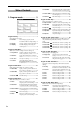
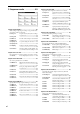
Table of Contents 3–6: Filter2 Mod. Keyboard tracking and controller settings to modulate the filter 2 cutoff frequency .................................................................... 21 3–7: Filter2 LFO Mod. Filter 2 LFO settings to modulate the filter 2 cutoff frequency .................................... 21 1. Program mode. . . . . . . . . . . . . 1 3–8: Filter2 EG Filter 2 EG settings ................................... 21 Program P4: Edit–Amp..................................
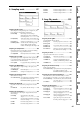
Program Combination P7: Edit–Arp...............................44 Make settings for arpeggiators A and B. 7–1: Setup Assign arpeggiators to each timbre .......44 7–2: Arpegg. A Select an arpeggio pattern and make settings for arpeggiator A .......................45 7–3: Arpegg. B Select an arpeggio pattern and make settings for arpeggiator B ........................45 7–4: Scan Zone Specify the ranges of notes and velocities that will operate the arpeggiator ............45 Combination 2.
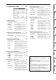
3. Sequencer mode . . . . . . . . . . 49 Sequencer P4: Zone/Ctrl................................ 66 Specify the note range and controllers for each track. 4–1: Key Z 1–8 4–2: Key Z 9–16 .................................................................... 66 4–3: Vel Z 1–8 Specify the range of velocities sounded by each track .................................................. 67 4–4: Vel Z 9–16 ....................................................................
Parameter settings for IFX3 ...................122 8–6: IFX 4 Parameter settings for IFX4 ...................122 8–7: IFX 5 Parameter settings for IFX5 ...................122 Program 8–5: IFX 3 Combination 4. Sampling mode . . . . . . . . . . . 87 Sequencer 5. Song Play mode . . . . . . . . . 123 Sampling P0: Recording ............................... 88 Make sample recording settings such as input level, and basic settings for multisamples and samples.
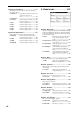
Song Play P8: Insert Effect ........................... 131 Specify the bus for the output of each track, and make insert effect settings. 8–1: Routing 1–8 6. Global mode . . . . . . . . . . . . 135 Specify the bus and the master effect send levels for the output of each track ......................................................... 131 8–2: Routing 9–16 ..................................................................
Program 7. Disk mode . . . . . . . . . . . . . . 155 8. Effect Guide. . . . . . . . . . . . . 177 Files, directories, and icons ........................................................... 155 0–1: Load Load the selected file or directory into internal memory ..................................... 156 Overview................................................. 177 0–2: Save Save data from internal memory to various media ......................................... 165 2. Dynamic modulation (Dmod) ........
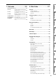
022: St. Env. Flanger (Stereo Envelope Flanger) .............................. 199 067: Comp – Cho/Flng (Compressor – Chorus/Flanger)................... 221 023: Stereo Phaser ........................................................................... 199 068: Comp – Phaser (Compressor – Phaser) ................................... 222 024: St. Random Phaser (Stereo Random Phaser) .......................... 200 069: Comp – Mt. Delay (Compressor – Multitap Delay) .................... 222 025: St. Env.
Alternate Modulation Source (AMS)................. 241 About Alternate Modulation............................................................... 241 Program 9. Appendices . . . . . . . . . . . . . 241 Replacing the calendar battery..........................................................297 Connecting external SCSI devices................... 298 Packet writing support on the TRITON STUDIO .... 299 AMS (Alternate Modulation Source) List ...........................................
xii
Program 1. Program mode Program Select Program P0: Play 0–1: Perf. Edit (Performance Edit) 0–1 0–1a P2 P1 Here you can select a specific program. When this parameter is selected, you can select programs using the [ ] [ ] keys, numeric keys [0]–[9], or [VALUE] dial. When you press the popup button, the “Bank/Program Select” menu will appear. This displays programs by bank, and allows you to select a program.
10’s Hold Pitch Stretch 1 Press the [./10’s HOLD] key to display . The 10’s place of the program number will be held (fixed). 2 Now you can press any numeric key [0]–[9] to input the 1’s place of the program number with a single keystroke. 3 You can use the [ ] [ ] keys to change the value of the 10’s place. 4 To cancel, press the [./10’s HOLD] key to turn off the display. This simultaneously adjusts the Transpose and Tune of the oscillator.
Program P0 P1 P3 P2 It is not possible to write to banks G–g(d). If you have edited a program from banks G–g(d) and wish to write it, you must write to banks INT-A–INT-E or EXB-A– EXB-G. 5 To execute the Write Program operation, press the OK button. To cancel, press the Cancel button. P4 [–10...0...+10] This adjusts the master effect “Return 1” and “Return 2” (9– 1b) settings as a whole. With an adjustment of +00, the value of the program parameters will be unchanged.
0–3: Sampling Here you can adjust the settings for the analog/digital audio signal input (AUDIO INPUT, S/P DIF, EXB-mLAN), and the settings related to sampling in Program mode. You can sample either an external audio signal, or a performance played on the TRITON STUDIO. When sampling in Program mode, you can listen to the performance of the TRITON STUDIO’s arpeggiator etc.
Save to [RAM, DISK] Specifies the destination to which the data will be written during sampling. RAM: Sample into sample memory (RAM). If you sample into sample memory (RAM), you will be able to immediately hear the sample in Program mode or Sampling mode. Settings for the writing destination RAM Bank and Sample No., and settings for automatically converting the sample to a program, are made by the page menu command “Select Bank & Smpl No.” (0–3C).
The “Auto +12 dB On” setting will not affect samples that you recorded to the internal hard disk etc. when “Save to” (0–3b) is set to DISK. You can use “WAVE File Play Level” (Global P0: 0-2a) to set the playback level. ▼ 0–3: Page Menu Command 0–1A 0–1A 0–3A 0–3A 0–3B 0–3B 0–3C 0–3D 0–3A: Metronome Setup Specifies the output destination and volume of the metronome that is sounded when you use “Trigger” Sampling START SW to begin sampling. 1 Select “Metronome Setup” to access the dialog box.
P0 Here you can make basic settings for the program, such as oscillator mode and scale type. 1–1: Program Basic P1 Specifying the save destination for a WAVE file Program P1: Edit–Basic 1–1 1 Select the “Select Directory” to access the dialog box. 1–1b P3 1–1a P2 This lets you select the disk (internal hard disk, etc.) and directory on which the WAVE file created by sampling will be saved, and specify a filename.
When legato is on, multiple note-on message will not retrigger the voice. If one note is already on and another note is turned on, the oscillator sound, envelope, and LFO will not be reset, and only the pitch of the oscillator will be updated. This setting is effective for wind instrument sounds and analog synth-type sounds. Off (unchecked): Legato is off. Notes will always be retriggered when note-on occurs. When legato is off, multiple note-on’s will retrigger the voice at each note-on.
Program P0 The EXB* display will differ depending on the type of option board. P1 If a program that uses a multisample from an EXB-PCM series board is selected, but the corresponding EXBPCM (expansion board) is not installed, the “High MS Bank” field will indicate ROM. In this case, the program will not sound. By re-selecting the multisample bank, you can make the program sound.
Lvl (High Level) [000…127] Specifies the level of the multisample. Depending on the multisample, high settings of this parameter may cause the sound to distort when a chord is played. If this occurs, lower the level. The playback level for a RAM multisample is also affected by the “+12 dB” (Sampling P2: 2–1c) setting for each sample. If the “+12 dB” setting is on, the playback will be approximately +12 dB louder.
Program Here you can specify the velocity range at which each oscillator will sound. The “Velocity M.Sample” SW Lo→Hi” (1–2c) setting in conjunction with these “OSC 1/2 Velocity Zone” settings will determine the velocity ranges in which the High and Low multisample or drum kit will sound. P0 1 Select “Sample Parameters” to access the dialog box. 1–3: Velo. Zone (Velocity Zone) P1 These settings are made for the selected multisample.
1–4: Controller (Controller Setup) These settings specify the functions of the [SW1] key, the [SW2] key, and the B-mode functions of REALTIME CONTROL knobs [1]–[4] in Program mode. Program P2: Edit–Pitch Here you can make pitch modulation settings for oscillators 1 and 2. 1–4 1–4a 2–1: OSC1 P.Mod (OSC1 Pitch Mod.) These settings specify how key position (note number) will affect the pitch of oscillator 1, and select the controllers that will affect the oscillator 1 pitch and specify the depth of control.
[Off, (FEG, AEG, EXT)] Selects the source that will modulate the pitch of oscillator 1 (“AMS List” ☞p.242). Intensity (AMS Intensity) [–12.00…+12.00] Specifies the depth and direction of the effect produced by “AMS (Pitch AMS).” With a setting of 0, no modulation will be applied. With a setting of 12.00, the pitch will change up to one octave.
The “LFO1 Intensity,” “JS+Y (LFO1 JS+Y Int.)” and “AMS (LFO1 AMS)” settings will be added to determine the depth and direction of the pitch modulation applied by OSC1 LFO1 (☞p.244). Attack (Attack Level) [–99…+99] Specifies the amount of pitch change when the attack time has elapsed. Release (Release Level) LFO2: LFO2 Intensity [–12.00…+12.00] JS+Y Int. (LFO2 JS+Y Int.) [–12.00…+12.00] AMS (LFO2 AMS) [Off, (PEG, FEG, AEG, KT, EXT)] Intensity (AMS Intensity) [–12.00…+12.
At (AMS SW Attack) Program [–, 0, +] Specifies the direction of change in “Start (Start Level)” caused by “AMS1 (Level Mod. AMS1).” If “Intensity (AMS1 Intensity)” is a positive (+) value, a setting of + will raise the EG level, and a setting of – will decrease it. With a setting of 0 there will be no change. Specifies the direction in which “AMS (Time Mod. AMS)” will affect the “Attack (Attack Time).
When the “Filter Type” is Low Pass Resonance, the cutoff will have a steeper slope. Program P3: Edit–Filter Low Pass Here you can make settings for the filters that will be used by oscillators 1 and 2. You can select either a 24 dB/octave low pass filter with resonance, or a series connection of a 12 dB/ octave low pass filter and a 12 dB/octave high pass filter. When “Oscillator Mode” (1–1a) is set to Single, filter 1 will be used, and when it is set to Double, filters 1 and 2 will be used.
Here you can make settings to specify how keyboard tracking, controllers, and filter 1 EG intensity will control the Filter 1 cutoff frequency “Frequency” (A/B Frequency) to modify the tone. When “Filter Type” (3–1a) is Low Pass Resonance, parameters for filter B will not be displayed. Program P0 How cutoff frequency is affected by keyboard location and the Ramp setting (“Intensity to A” and “Intensity to B” = +50) Cutoff frequency P1 3–2: Filter1 Mod.
ters (3–4a) are in the “+” area, and darker when they are in the “–” area. With negative (–) settings, the sound will become darker when the EG levels set by Filter 1 EG “Level” and “Time” parameters (3–4a) are in the “+” area, and brighter when they are in the “–” area.
Break (Break Point Level) Program [–99…+99] Specifies the depth and direction of the effect that “AMS (LFO1 AMS)” will have on filter 1B (☞“Intensity to A (LFO1 AMS Int. to A)”). [–99…+99] Specifies the cutoff frequency after the decay time has elapsed. Sustain (Sustain Level) [–99…+99] P1 [–99…+99] P2 Specifies the cutoff frequency that will occur when the release time has elapsed. Time: These parameters specify the time over which each change will occur.
At (AMS SW Attack) [–, 0, +] Specifies the direction in which “AMS (Level Mod. AMS)” will affect “Attack (Attack Level).” When “Intensity (AMS Intensity)” has a positive (+) value, a setting of + for this parameter will allow “AMS (Level Mod. AMS)” to raise the EG level, and a setting of – will allow “AMS (Level Mod. AMS)” to lower the EG level. With a setting of 0 there will be no change. Br (AMS SW Break) [–, 0, +] Specifies the direction in which “AMS (Level Mod.
Program P0 Make settings for amp 1 which controls the volume of oscillator 1, and amp 2 which controls the volume of oscillator 2. Pan settings are also made here. P1 4–1 P2 4–1a P5 P4 P3 4–1b P7 4–1: Amp1 Level/Pan These parameters control the volume and pan of oscillator 1. P8 Make settings for filter 2 which controls the sound of oscillator 2.
Intensity [–99…+99] Specifies the depth of the effect produced by “AMS (Pan AMS).” For example if “Pan (Amp1 Pan)” is set to C064 and “AMS (Pan AMS)” is Note Number, positive (+) values of this parameter will cause the sound to move toward the right as the note numbers increase beyond the C4 note (i.e., as you play higher), and toward the left as the note numbers decrease (i.e., as you play lower). Negative (–) values of this parameter will have the opposite effect.
Specifies the depth and direction of the effect that “OSC1 LFO 2” (5–2) will have on the volume of oscillator 1. Refer to the preceding sections “LFO1 Intensity”–“Intensity (AMS Intensity).” ▼ 4–2: Page Menu Command Program P0 [00…99] P2 Slope (Slope Time) P1 Specifies the time over which the volume will change from when it reaches the attack level until it reaches the break point level.
Br (AMS SW Break) [–, 0, +] Rl (AMS1 SW Release) [–, 0, +] Specifies the direction in which “AMS (Level Mod.AMS)” will change “Break (Break Point Level).” If “Intensity (AMS Intensity)” is set to a positive (+) value, setting this parameter to + will allow AMS to increase the EG level, and setting this parameter to – will allow AMS to decrease the EG level. With a setting of 0, no change will occur. Specifies the direction of the effect that “AMS1 (Time Mod. AMS1)” will have on “Release (Release Time).
5–1: OSC1 LFO1 Make settings for the “OSC1 LFO1,” which is the first LFO that can be used for oscillator 1. 5–1 Program Pitch offset = –99 offset = 0 offset = +99 Key Sync. P0 Pitch at note-on [Off, On] Fade P1 On (checked): The LFO will start each time you press a key, and an independent LFO will run for each note. Off (unchecked): The LFO effect that started when the first key was pressed will also apply to subsequently-played notes.
5–4: OSC2 LFO2 5–1c: Frequency MIDI/Tempo Sync. MIDI/Tempo Sync. [Off, On] On (checked): The LFO frequency will synchronize to the tempo (MIDI Clock). In this case, the values you specified for “Frequency” (5–1a) and Frequency Modulation (5–1b) will be ignored. Base Note (Sync. Base Note) [ , , , , , , , ] Times (Sync. Times) [01...16] When “MIDI/Tempo Sync.” is checked, these parameters set a note length relative to “ (Tempo)” and the multiple (“Times”) that will be applied to it.
[–100...+100(%)] This parameter shifts the timing of the odd-numbered notes of the arpeggio. When Resolution = P00...P04 Preset arpeggio patterns U000(I-A/B)...U199(I-A/B) Preloaded arpeggio patterns 2 3 4 5 6 7 8 9 P1 Step 1 P0 [P00...P04, U000(I-A/B)...U506(User)] Selects the arpeggio pattern. U200(E-A)...U215(E-A) –50 Swing U216(E-B)...U231(E-B) –25 +25 +50 P2 ☞Refer to BG p.130. Pattern* Program Swing 7–1b: Arpeggiator Setup U232(E-C)...
1 Select “Copy Arpeggiator” to access the dialog box. Program P8: Edit–Insert Effect ☞For details on insertion effects, refer to p.178 “8. Effect Guide.” 2 In “From” specify the source of the arpeggio settings (mode, bank, number) that you wish to copy. 3 If you are copying from Combination, Song, or Song Play mode, specify whether you wish to copy from A or B. 4 To execute the Copy Arpeggio operation, press the OK button. To cancel, press the Cancel button.
[000...127] Sets the volume (send level) at which the output of oscillator 1 will be sent to master effect 1. This is valid when “BUS Select” (8–1c) is set to L/R or Off. If “BUS Select” is set to IFX1, IFX2, IFX3, IFX4 or IFX5, the send levels to master effect 1 and 2 are set by “Send 1” and “Send 2” (8–2a) after passing through IFX 1/2/3/4/5 of the Insert FX pages. Send2 (to MFX2) [000...127] Program P0 P1 P2 Send1 (to MFX1) 4 Select the insert effect copy destination.
8–3: IFX 1 8–4: IFX 2 8–5: IFX 3 8–6: IFX 4 8–7: IFX 5 Category/IFX Select menu: When you press the popup button, a “Category/IFX Select” list will appear. Press a tab to select a category of effects, and select an effect from that category. Press the OK button to execute, or press the Cancel button to cancel. IFX1, 2, 3, 4, 5 On/Off [Off, ON] Switches the insert effect on/off. When this is OFF, the input will be output unchanged. (For 000: No Effect, on/off will produce the same result.
Here you can select the master effect types, switch them on/ off, specify chain order, and set the master EQ. 9–1 Chain Program [Off, On] On (checked): Chain (series connection) will be turned on for MFX1 and MFX2. Off (unchecked): MFX1 and MFX2 will operate in parallel. Chain Direction 9–1a P0 CC#94 can be used to switch the MFX on and off. A value of 0 will be off, and a value of 1–127 will be the original setting. This is controlled on the global MIDI channel “MIDI Channel” (Global P1: 1–1a).
▼ 9–1: Page Menu Command 0–1A 9–1A 9–1B 9–1A: Copy Master Effect This command lets you copy any desired effect settings from Program, Combination, Song, Sampling, or Song Play mode. 9–2: MFX 1 9–3: MFX 2 Makes effect parameter settings for the MFX1 and 2 effects that were selected in the Master FX page (9–2). (☞p.187–) Effect dynamic modulation (Dmod) is controlled on the global MIDI channel “MIDI Channel” (Global P1: 1–1a). (“D.mod” ☞p.247) 0–1 1 Select “Copy Master Effect” to access the dialog box.
2. Combination mode 0–1: Prog. Select (Program Select) 0–1 Category Combination In this display page you can select and play Combinations. A Combi allows you to use up to eight programs at once. 1 Press the popup button located at the left of “Combination Select” to access the Bank/Combination Select menu. 2 Press one of the tabs located at the left or right to select a bank. 3 Select a combination from the list. You can directly press your choice within the list, or use the [ ] [ ] keys.
0–1b: Selected Timbre Information This displays information on the selected timbre (1–8). T (Timbre) [01...08] Indicates the timbre number and the bank/number/name of the program that is selected for the timbre. Ch [01...16, Gch] Indicates the MIDI channel number specified for the timbre. 0–1c: Timbre Number, Category, Bank/Program, Status Timbre Number (1...8) Indicates the timbre number. The parameters below “Timbre Number” let you make settings for that timbre.
▼ 0–1: Page Menu Command 0–2: Mixer Here you can set the pan and volume for each timbre 1–8. 0–1A 0–1 0–1B 0–1A: Write Combination Combination 0–1a 0–1b 0–1c This command writes an edited combination into the TRITON STUDIO’s internal memory. Be sure to write any combination that you wish to save. If the power is turned off or a different combination selected before you write an edited combination, your edits cannot be recovered. For the procedure, refer to “Write Program” (Program P0: 0– 1A).
Volume [000...127] Adjusts the volume of each timbre 1–8. The volume of each timbre is determined by multiplying this volume value with the MIDI volume (CC#7) and expression (CC#11). If “Status” (0–1c, 2–1b) has been set to INT, incoming MIDI CC#7 or CC#11 messages will control the volume of a timbre. (However these messages will not affect the setting of this parameter.) If “Status” is EXT or EX2, the value of this parameter will be transmitted as MIDI CC#7 when the combination is changed.
0–5b: Sampling Setup Combination P1: Edit–Program/Mixer 1–1: Program/Mixer Combination Source BUS [L/R, Indiv.1/2] Trigger [Sampling START SW, Note On] Metronome Precount [Off, 4, 8, 3, 6] Save to [RAM, DISK] Mode (Sample Mode) [L-Mono, R-Mono, Stereo] Sample Time [min sec] For each timbre 1–8, set the bank, program, pan and volume. 0–1 1–1a Make settings for sampling in Combination mode.
Combination P2: Edit–Trk Param 2–2: OSC These settings specify how each timbre will be played. 0–1 2–1: MIDI Channel (MIDI Ch) 2–1a Here you can make MIDI settings for each timbre. 2–2a 0–1 2–1a 2–1b MSB LSB 2–2a: Force OSC Mode, OSC Select, Portamento Force OSC Mode 2–1a: Combination Name, Selected Timbre Information, Timbre Number, Program Category Combination Name Displays the bank, number, and name of the combination selected in Combination P0: Play.
2–3: Pitch ▼ 2–3: Page Menu Command Here you can make pitch-related settings for each timbre. 0–1A 2–3 0–1B 2–3a 2–3A: Detune BPM Adjust P1 1 Select “Detune BPM Adjust” to access the dialog box. P2 [–24…+24] P0 If the program of a timbre uses a phrase or rhythm loop multisample (or sample that was created in the Sampling mode) is matched to a specific BPM, you can use this Utility to modify its BPM value. “Detune BPM Adjust” changes the BPM of a phrase or rhythm by modifying its pitch.
2–4: Other Here you can make various other settings for each timbre. 0–1 2–1a 2–4a 2–4a: Delay, Use Program’s Scale, Scale Delay [ms] (Delay Time) [0000…5000, KeyOff] For each timbre, this specifies a delay time from note-on until the sound begins. KeyOff: The note will begin sounding at note-off. In this case, the sound will not die away if the sustain level of the program’s amp EG is other than 0. This setting is used when creating harpsichord sounds. Normally you will set this to 0.
3–2: MIDI 2 (MIDI Filter –2) 3–3a: Enable Realtime Control Knob –1...4 0–1 Enable Realtime Control Knob –1 [Off, On] 3–2a Enable Realtime Control Knob –2 Combination Specifies whether or not the A-mode MIDI control message CC#74 (the TRITON STUDIO’s low pass filter cutoff frequency) and the B-mode MIDI control message assigned to knob [1] will be transmitted and received.
Combination P4: Edit–Zone/Ctrl 4–1: Key Z (Key Zone) These settings specify the keyboard range in which each timbre will sound. The top/bottom key parameters specify the range of notes in which timbres 1–8 will sound, and the top/bottom slope parameters specify the range over which the original volume will be reached. By setting timbres of different sounds to ranges that do not overlap, you can play different sounds in different ranges of the keyboard (Key Split).
Top Velocity [1…127] Specifies the maximum velocity value that will sound each timbre 1–8. Top Slope 4–4: Controller (Control) Here you can set the Combination mode functions of the [SW1] key, [SW2] key, and the B-mode functions of REALTIME CONTROL knobs [1]–[4]. Combination 4–2a: Top Velocity, Top Slope, Bottom Slope, Bottom Velocity 0–1A 1–1a [0…120] 4–4a 0: The volume will be at the original value from the top velocity. 120: The volume will decrease as the velocity approaches the top velocity.
If you want the note data generated by the arpeggiator to be recorded on the external sequencer, turn Local Control ON, and turn off the echo back function on your external sequencer. Combination P7: Edit–Arp. These parameters specify how the arpeggiator will function within the combination. Two arpeggiators can run simultaneously.
Key Sync.* Keyboard* ▼ 7–1: Page Menu Command [Off, On] [Off, On] 0–1B 7–1A Combination These parameters are the arpeggiator settings for the combination. (☞“Program P7: Edit-Arpeggiator”) * These parameters can also be set from “0–3(4): Arpegg. A(B)”. 0–1A 7–1A: Copy Arpeggiator This command can copy arpeggiator settings from another location to the current Combi. 1 Select “Copy Arpeggiator” to access the dialog box.
Combination P8: Edit–Insert FX You can also specify the bus routing for the program used by each timbre 1–8. ☞For details on insertion effects, refer to p.178 “8. Effect Guide.” 8–1: Routing Specifies the bus to which the program oscillator(s) used by each timbre 1–8 will be sent. You can also set the send levels to the master effects from this page. 8–1 8–1a 2–1a 8–1b IFX2–IFX5) (8–2), and for the sound that has passed through the IFX, set “BUS Select” (8–2) to either 1/2 or 3/4.
Here you can select the type of each insert effect, turn it on/ off, and make chain settings etc. 8–1 8–2a 8–3: IFX 1 8–4: IFX 2 8–5: IFX 3 8–6: IFX 4 8–7: IFX 5 Combination 8–2: Insert FX These are the parameters for IFX1, 2, 3, 4, and 5 that were selected in the Insert FX page (☞p.187–). P1 P0 8–1 8–3a P3 P4 P7 Ctrl Ch [Ch01...
Combination P9: Edit–Master FX ☞For details on master effects, refer to p.182 “8. Effect Guide.” 9–2: MFX 1 9–3: MFX 2 Here you can set the parameters for the MFX 1 and 2 effects that were selected in the Master FX page (☞p.187). 9–1 9–2a 9–1: Master FX Here you can select the type of each master effect, turn it on/off, and make chain and master EQ settings.
3. Sequencer mode Sequencer 0–1b P2 P1 P0 0–1c Location P3 0–1a: Location, Meter, Tempo, Tempo Mode, Song Select, Track Select, Reso, RPPR On/Off [001:01.000…999:16.191] P4 This display shows the current position in the song. From the left, the numbers are the measure, beat, and clock. When you modify these values, the current location will change. P5 These settings and any song data that you have recorded will not be backed up when the power is turned off.
Recording from measure 2 of track 2 when Meter =7/8 when Meter = **/** Track 1 1 (4/4) Track 2 1 (4/4) Track 1 1 (4/4) 2 (3/4) Track 2 1 (4/4) 2 (3/4) 2 (3/4) Track 1 1 (4/4) Track 2 1 (4/4) 3 (4/4) Track 1 1 (4/4) 2 (7/8) 3 (7/8) 4 (7/8) 3 (4/4) Track 2 1 (4/4) 2 (7/8) 3 (7/8) 4 (7/8) 3 (4/4) Recording 2 (3/4) 3 (4/4) 3 (4/4) Recording Changing the time signature in the middle of a song If you know beforehand the location at which you wish to change time signatures in the
RPPR On/Off [Off, On] This turns the RPPR (Realtime Pattern Play/Recording) function on/off. RPPR lets you assign a pattern to each note of the keyboard, so that the pattern will playback (or be recorded) when you press the appropriate key. On (checked): The RPPR function will be on. If a pattern has been assigned to each key in the P6: Pattern/RPPR, RPPR Setup page, pressing that key will perform the assigned pattern (☞P6–3: RPPR Setup). 0–1(2)b: Selected Track Information (01...08 (09...
When the page menu command “Solo Selected Track” (0–1B) is on, its Solo status will be given priority (if ON). When you press “SOLO ON/OFF” or the parameter of another track, only that track will be soloed, and will sound. 0–1E: Copy From Song This command copies all of the setting data and musical data from the specified song to the currently selected song. 1 Select “Copy From Song” to access the dialog box.
For details on the content that will be corrected, refer to “If the recorded performance is not reproduced correctly during playback” (☞BG p.96). The content described here will be corrected automatically. Depending on the settings of the combination, it may be necessary to make additional changes to the track settings in addition to the settings here. Sequencer P1 P2 P3 6 To execute, press the OK button. When you execute, “Measure” will count up automatically. You may then copy patterns as well.
0–1H: Save Template Song (Save as User Template Song) This command saves the program selections, track parameters, and effect settings etc. of the current song as a user template song U00–15. The settings you save here can also be loaded in Song Play mode. 1 Select “Save Template Song” to access the dialog box. 3 If “Ignore Tempo” is checked, the playback tempo and note length will be ignored, and fast-forward and rewind will be performed as fast as possible.
Here you can set the pan and volume of each track. The pan and volume that you specify here will be used when you playback or record from the beginning of the song. If you change the settings during recording, the changes will be recorded as musical data, and pan and volume will change during playback. You can also change the settings during playback. However when the song reaches a location where pan or volume data was recorded, the settings will change accordingly.
Example) When “Play Intro” is checked 0–7b: Sampling Setup Source BUS Save to Mode (Sample Mode) Sample Time Track 1 will loop as follows. M001–M002–M003–M004–M003–M004–M003–M004… When “Play Intro” is not checked [L/R, Indiv.1/2] [RAM, DISK] [L-Mono, R-Mono, Stereo] [min sec] Make sampling-related settings for Sequencer mode. (☞Program P0: 0–3) Trigger [Sampling START SW, Note On, Threshold, Sequencer START SW] Specifies the trigger that will initiate sampling.
The “Auto +12 dB On” setting is made independently for Program, Combination, Sequencer, and Sampling modes. 5 “Convert to” lets you specify whether the sample will automatically be converted to a program after sampling. You can also specify whether a note event will be created at the time of sampling. If the “Program” check box is checked, the sample will automatically be converted to a program.
Auto Punch In Select this method when you wish to automatically rerecord selected portions of a previously-recorded track. If you select Auto Punch In, the display will indicate “M***– M*** (Auto Punch In Start Measure–Auto Punch In End Measure)” at the right, allowing you to specify the range of measures that will be rewritten. Press the SEQUENCER [REC/WRITE] key and then the SEQUENCER [START/STOP] key, and playback will occur until the specified measure is reached.
Tempo Mode 1–1d 1–1a: Location, Meter, , Tempo Mode, Cue List Select, Track Select Location [0001:01.000…9999:16.191] This displays the current location within the selected cue list. From the left, the numbers indicate the measure, beat, and clock. Each can be set separately, and this will change the current location within the cue list. The range of the beat and clock will depend on the time signature of the corresponding song.
Song (Cue Edit - Song) [S000...S199: name/End, Continue to Step01] S000...S199: Specifies a song for each step. This cannot be edited during playback. End and Continue to Step01 can be specified only for the last step of the cue list. End: Playback will stop at the last step of the cue list. Continue to Step01: At the last step of the cue list, playback will return to “Step” 01 and the cue list will continue playing endlessly. To stop, press the SEQUENCER [START/ STOP] key. Repeat [01...
• Song/Track parameter settings for “Step” 01 Song/Track parameters will use the settings of the “Step” 01 song. • Patterns Patterns in the “Step” 01 song will be copied as patterns of the converted song. If there is a second or subsequent repeat for “Step” 01, or if the tracks of “Step” 02 and subsequent songs contain patterns, they will be expanded into track events (musical data). The following track parameters will not be reflected in the conversion.
numerous repeats have been specified, or if many patterns are used by the songs, you should try executing the “Convert to Song” command from time to time as you create the cue list, in order to verify the amount of memory that will be required for the conversion. A cue list that is longer than 999 measures cannot be converted into a song. 1–1E: Copy Song Sequencer P2: Trk Param 2–1: MIDI Ch 1–8 (MIDI Ch T01–08) 2–2: MIDI Ch 9–16 (MIDI Ch T09–16) Here you can make MIDI-related settings for each track.
Bank Select (When Status=EX2) [000:000...127:127] When “Status” is set to EX2, this sets the bank number that will be transmitted. The left value is the MSB, and the right value is the LSB. When “Status” is other than EX2, this setting has no effect. CC#65 of 127 and CC#05 of 1–127 will be transmitted. If this is set to PRG, nothing will be transmitted. This data is transmitted and received on the MIDI channel specified for each track by “MIDI Channel” (2–1a/ 2a).
Key ▼ 2–5: Page Menu Command 0–1A 0–1G 0–1B 0–1H Random 0–1C 0–1I 0–1D 0–1J 0–1E 2–5A As this value is increased, an increasingly random deviation will be added to the pitch at each note-on (☞“Random” Program P1: 1–1c). 0–1F 2–5A: Detune BPM Adjust When the program selected for a track uses a phrase, rhythm loop multisample (or sample that was created to match a specific BPM in Sampling mode or loaded from disk in Disk mode) you can use this command to change the BPM of the phrase or rhythm.
Enable Portamento SW Sequencer P3: MIDI Filter [Off, On] Specifies whether or not MIDI control message CC#65 Portamento On/Off will be received. Sequencer [Off, On] P2 Enable JS X as AMS P1 3–3(4)a: Enable JS X as AMS, Enable JS+Y, Enable JS-Y, Enable Ribbon Allow incoming MIDI pitch bend messages (the X-axis of the TRITON STUDIO’s joystick) to control the AMS (☞p.242) that is specified for JS X. (This is not a reception filter for MIDI pitch bend messages.
3–5(6)a: Enable Realtime Control Knob 1...4 Enable Realtime Control Knob 1 Sequencer P4: Zone/Ctrl [Off, On] Specifies whether or not the A-mode MIDI control message CC#74 (the TRITON STUDIO’s low pass filter cutoff frequency) and the B-mode MIDI control message will be received.
4–7: Controller (Controller Setup) Here you can set the Top/Bottom Velocity parameters to specify the range of velocities that will be sounded by tracks 1–16, and Top/Bottom Slope specify the range over which the volume will be adjusted. These settings do not affect MIDI transmission/reception. All note data that is received will be recorded into the internal sequencer, and all note data from the internal sequencer or from the keyboard will be transmitted.
▼ 5–1: Page Menu Command Sequencer P5: Track Edit 5–1G 0–1A 5–1: Track Edit 5–1 0–1a 5–1b 0–1b 5–1J 5–1C 5–1K 5–1D 5–1N 5–1O 5–1P 0–1I 0–1J 5–1Q 5–1E 5–1L 5–1F 5–1M 5–1A: Step Recording Step recording allows you to specify the length and velocity of each note numerically, and to input the pitches from the keyboard. You can use the Rest button and Tie button to input a rest or tie.
The following table shows the number of clocks represented by each “Step Time” selection. 5–1B: Event Edit 3 Here you can edit individual events of music data that were input. • Inputting a tie If you press the Tie button without pressing the keyboard, the previously-input note will be tied, and lengthened by the amount specified in 4. If you press the Tie button while holding down a note, the note you are playing will be tied, and lengthened by the amount specified in 4.
• Deleting an event Select the event that you wish to delete, and press the Cut button to delete the event. • Moving an event You can use the Cut button and Insert button to move an event (by “cut and paste”). Use the Cut button to delete the event that you wish to move, then use the Insert button to insert it at the desired location. You can also move an event by modifying its “BT” value. • Copying an event Select the event that you wish to copy, and press the Copy button.
5 If you check “All Tracks,” the specified type of data will be erased from all tracks. 6 To execute the Erase Measure command, press the OK button. To cancel, press the Cancel button. Example: When measures 2 and 3 (3/4 time) of track 2 are deleted, the measures that were at 4 and 5 are moved forward, and their time signature will change to 3/4.
5–1J: Copy Measure Time signature = **/** Track 1 1 (4/4) 2 (4/4) 3 (3/4) 4 (5/4) 5 (2/4) Track 2 1 (4/4) 2 (4/4) 3 (3/4) 4 (5/4) 5 (2/4) This command copies the measures of musical data specified as the “From” source to the begining of the measure specified as the “To” location. When you execute the Copy Measure command, the existing track data at the copy destination will be rewritten.
5–1L: Create Ctrl Data (Create Control Data) 5–1M: Erase Ctrl Data (Erase Control Data) This command gradually varies continuous-type data (e.g., control change, after touch, pitch bend, tempo) in the specified area. This command erases data such as control changes, after touch, pitch bend, or tempo in the specified range. Example: The controller is aftertouch. Starting location is 3:48, ending location is 4:24, and end value is set to 100.
In “From Measure” and “To End of Measure,” specify the measures. In “Beat.Tick” specify the beat and clock. (By default, “From Measure” and “To End of Measure” will be the range that you specified in the Track Edit page.) 4 In “Kind,” select the type of musical data (events) that you wish to quantize. All: Quantization will be applied to all performance data. Note: Quantization will be applied only to note data. Use “Bottom” and “Top” to specify the range of notes.
5–1P: Modify Velocity 5–1Q: Set Song Length This command modifies the velocity values of notes in the specified area so that they will change over time according to a selected curve. This command changes the length of the specified song. When it is executed, the length of the master track will change, and the number of measures played will change. 1 In “Track Select,” specify the track whose velocity will be modified. 2 Select “Modify Velocity” to access the dialog box.
Pattern (Pattern Bank) Sequencer P6: Pattern/RPPR On the TRITON STUDIO you can use preset patterns P000– 149, and user patterns U00–99. One song can contain up to one hundred user patterns. Preset patterns suitable for use in a drum track are provided in memory, and can be selected from any song. Preset patterns cannot be edited, but you may copy a preset pattern to a user pattern, and edit.
6–1D: Erase Pattern ▼ 6–1: Page Menu Command This command erases the data from the selected pattern. 0–1A 6–1F 6–1A 6–1G 6–1B 6–1H 6–1C 6–1I 6–1D 0–1I 1 Use “Pattern” and “Pattern Select” to specify the pattern. 2 Select “Erase Pattern” to access the dialog box. 6–1E Length (beats, clocks) 6–1B: Event Edit Here you can edit individual events of the musical data in a pattern. Use “Pattern” and “Pattern Select” to specify the pattern, and then select this command.
4 In To: “Song” and “Pattern,” select the bounce destination song and pattern. For “Pattern,” only user patterns U00–U99 can be specified. 5 To execute the Bounce Pattern command, press the OK button. To cancel, press the Cancel button. 6–1G: Get From Track This command takes musical data from a track and loads it into the specified pattern. 1 Use “Pattern” and “Pattern Select” to specify the pattern. 2 In “Pattern Parameter” (6–1C), specify the pattern length of the “get” destination.
6–3: RPPR Setup 6–3b: Keyboard & Assigned drawing In the RPPR Setup page, RPPR is turned on automatically. This will be the same result as when the RPPR check box (0–1a) in each page is checked. 6–1 6–3a Unassigned keys Selected key KEY (Key Select) Sequencer 6–3c: RPPR Setup [C#2...C8] Assign P0 Specifies the key to which you want to assign an RPPR pattern. The following parameters will apply to the key that you select here.
2 Set “KEY” to D2, and press the Revert button. The “Pattern (Pattern Bank),” “Pattern Select,” and “Track” settings that you specified in step 1 will be copied automatically. 3 Edit only “Pattern Select.” Select “Pattern Select,” and press the [ ] key to select P01: Pop&Balad 2/Std. 4 Set “KEY” to D#2, and press the Revert button. The “Pattern (Pattern Bank)” P01: Pop&Balad 2/Std you selected in step 3, as well as the “Pattern Select” and “Track” settings, will be copied automatically.
7–1(2)a: Arpeggiator Assign, Arpeggiator Run A, B When “MIDI Clock” is External MIDI or External mLAN, the MIDI realtime clock messages transmitted from the external MIDI device connected to MIDI IN or the mLAN connector can perform the same type of control. Even in this case, you can start/stop using the SEQUENCER [START/STOP] key of the TRITON STUDIO’s sequencer.
• Alternatively, you could choose Track01 in “Track Select” to run arpeggiator A for tracks 1 and 2, and use an external MIDI device connected to the TRITON STUDIO’s MIDI IN to send note data to MIDI channel 3 to play arpeggiator B.
7–5b: Scan Zone A/B Sequencer P8: Insert Effect Top Key Bottom Key [C–1...G9] [C–1...G9] Specify the range of notes (keys) that will trigger arpeggiator A. “Top Key” is the upper limit, and “Bottom Key” is the lower limit. Top Velocity Bottom Velocity [001...127] [001...127] Specify the range of velocities that will trigger arpeggiator A. “Top Velocity” is the upper limit, and “Bottom Velocity” is the lower limit. Here you can make insert effect settings, and specify the bus etc.
Send1 (MFX1) Send2 (MFX2) [000...127] [000...127] Here you can adjust the send levels from tracks 1–16 to master effects 1 and 2. This is valid when “BUS Select” is set either to L/R or Off. If IFX 1, 2, 3, 4, or 5 is selected, the send level to the master effects 1 and 2 is set by the “Send 1” and “Send 2” parameters located in the Insert FX page, after the signal passes through IFX 1–5. These settings have no effect if “BUS Select” is set to 1, 2, 3, 4, 1/2 or 3/4.
8–4: IFX 1 8–5: IFX 2 8–6: IFX 3 8–7: IFX 4 8–8: IFX 5 Sequencer P9: Master Effect ☞For details on the master effects, refer to p.182 “8. Effect Guide.” 9–1: Master FX 8–1 8–4a Here you can select the type of master effects, turn them on/ off, and make chain and master EQ settings. These parameters are the same as in Program mode. ☞“Program 9–1: Master FX (Master Effects)” Sequencer Set the parameters for the effects selected for IFX 1–5 in the Insert FX page (☞p.187–).
9–2: MFX 1 9–3: MFX 2 Here you can set the parameters of the MFX 1 and 2 effects that were selected in the Master FX page (☞p.187–). 9–1 9–2a 9–2(3)a: Ctrl Ch Ctrl Ch [Ch01...16, Gch] Specifies the MIDI channel that will control dynamic modulation (Dmod) for the master effects. If Gch is selected, the global MIDI channel “MIDI Channel” (Global P1: 1–1a) will be used. 9–4: Master EQ The master EQ is a three-band stereo EQ.
4. Sampling mode 6. Resampling can be performed by applying insert effects to one or more existing samples, and once again sampling them internally. You can select either “Auto,” where insert effect processing will be performed automatically on the sample you specify, or “Manual,” where you can manually apply an insert effect and play the sample manually for resampling.
Regardless of the page you are in, the selected multisample or sample will sound when you play the keyboard, allowing you to hear the edited content of that page. When you turn off the power, all multisample and sample data in Sampling mode will be lost. Before you turn off the power, be sure to save important data to floppy disk, hard disk, CD-R/RW or external SCSI device (☞BG p.60).
Keyboard range Highest note of the displayed keyboard By holding down the [ENTER] key and playing a note, you can select the corresponding index, and the specified key will be the base key and will be shown in gray. This displays the zones and original keys of the selected multisample. The black triangle shows the keyboard range, and the white triangle shows the C4 key. The note numbers at left and right show the keyboard note range that is displayed.
or “Insert” to open the dialog box. So that a new index can be created at the left of index 1, re-set the “Top Key” setting, and press the OK button. 0–1c: REC Sample Setup Here you can select the memory bank into which you will sample, specify the sampling time, and select either mono or stereo sampling. Save to • Set Zone Range: If you execute “Create” when it is not possible to create a new index according to the Create Zone Preference settings, the following dialog box will appear.
If the writing destination is (“Save to”) is RAM, and “Auto Optimize RAM” (Global P0: 0–3b) is not checked, unused sample RAM will accumulate, decreasing the amount of available sample memory (RAM). If this occurs, execute the page menu command “Optimize RAM” (0–1M) to reclaim unused RAM. The remaining amount of RAM can be checked in Sampling mode P0: Memory Status. The remaining amount of memory will depend on the following conditions: 1. The amount of memory that is installed. 2.
0–1A: Delete Sample 0–1d: Recording Level [dB] Recording Level [–inf, –72.0... 0.0...+18.0] This adjusts the signal level at the final stage of sampling. When you sample, make sure that the level is as high as possible without allowing the level meter to indicate “CLIP!!.” This setting can also be made in the P0–2: Input/Setup page. When you press the SAMPLING [REC] key you will enter sampling standby mode. Use the slider to adjust the signal level. Initially set this to 0.
Sample Memory 0000: NewSample_0000 Sample Data 0001: NewSample_0001 Sample Data "Copy Sample" with Sample Data Sample Memory 0000: NewSample_0000 Sample Data "Copy Sample" 0001: NewSample_0001 0–1E: Copy MS (Copy Multisample) This command copies the selected multisample to another multisample. The copy destination multisample number will automatically be included in the resulting multisample name. If necessary, use “Rename MS” (0–1F) to rename it.
However by executing the “Convert MS To Program” command, you can quickly and easily convert the Sampling mode settings into a new program, without having to make any Program mode settings as described above. 1 Use “MS (Multisample Select)” (0–1a) to select the multisample that you want to convert to a program. 2 Select “Convert MS To Program” to access the dialog box. 3 Press the text edit button to access the text edit dialog box, and input a multisample name of up to sixteen characters.
• The stereo sample that was created will be assigned automatically. 0–1J: Keyboard Display Example) If data already exists at the move destination sample number, the sample will not be overwritten; instead, all subsequent samples will be renumbered upward. This command selects the range of the keyboard display. Normally you will select 88Key Normal (A0–C8). 1 Select “Keyboard Display” to access the dialog box. Move 0003 to 0001 2 Use the radio buttons to select the displayed range.
Example) If data already exists at the move destination multisample number, the multisample will not be overwritten; instead, all subsequent multisamples will be renumbered upward. If you check “Take No.,” a two digit “take number” will be added at the end of the filename when it is saved. The number will automatically increment each time you sample. When sampling repeatedly, this is convenient since it allows each file to be saved with a different filename. If “Take No.
Pan [L000...C064...R127] Specifies the panning of the external audio signal being input (specified by “Input”). When inputting a stereo audio source, you will normally set Input1 to L000 and Input2 to R127. (For example settings, ☞p.91, BG p.37, 102) BUS (IFX/Indiv.) Select [L/R, IFX1...5, 1...4, 1/2, 3/4, Off] Specifies the bus to which the external audio signal will be sent. L/R: The external audio signal will be sent to the L/R bus. Normally you will select L/R. IFX1...
Metronome Precount [Off, 4, 8, 3, 6] Specifies whether the metronome will sound a countdown when you use “Trigger” Sampling START SW to begin sampling. This can be set only if “Trigger” is set to Sampling START SW. Off: Sampling will begin immediately when you press the SAMPLING [START/STOP] key from recording-standby mode.
Position [Right (to Selected Index), Left (to Selected Index)] Specifies whether the new index will be created at the right or left of the selected index. Right (to Selected Index): The new index will be created at the right of the currently selected index. Left (to Selected Index): The new index will be created at the left of the currently selected index. Zone Range [1 Key...127 Keys] Specifies the key range of the newly created index. 1Key: Each individual note of the keyboard will be an index.
Sampling P1: Sample Edit 1–1c: Sample waveform display, Edit Range Start, Edit Range End, Use Zero, Grid, ZOOM Here you can edit sample data (waveform data). Editing operations such as deleting unwanted portions of the waveform, reversing the waveform, or lowering the sampling frequency can be performed in detail while viewing the “sample waveform display.” Sample waveform display This displays the waveform of the selected sample.
Remarks on editing stereo samples • For stereo samples, the L channel and R channel samples are edited simultaneously. If you wish to edit only the L channel or R channel, select a mono multisample, and select either the L channel or R channel sample for editing. • For stereo samples, the display will indicate “Save to No.(L)” and “(R).” These respectively specify the writing-destination sample numbers for the L and R channels.
End: The sample data that lies after the “Edit Range End” will be deleted. 5 In “Save to No.,” specify the save destination sample number. By default, an unused sample number will be selected. The sample number cannot be specified if “Overwrite” is checked (☞p.101). For stereo samples, use “Save to No.(L)” and “(R)” to specify the save-destination of the L and R channels. 6 To execute the Truncate command, press the OK button. To cancel, press the Cancel button.
Pasting to a sample that contains sample data 2 Select “Insert” to access the dialog box. From the buffer If the buffer into which data was placed by the “Copy” command contains no data, the display will indicate “Source sample is empty.” 1 Use “Sample Select” (1–1b) to select the sample that you wish to edit, and set “Edit Range Start” to specify the starting address. The “Edit Range End” setting is ignored. 2 Select “Mix” to access the dialog box.
1 Use “Sample Select” (1–1b) to select the sample that you wish to edit, and set “Edit Range Start” to specify the starting address. The “Edit Range End” setting is ignored. 2 Select “Insert Zero” to access the dialog box. 3 To “Start” will indicate the starting address at which the data will be inserted. 4 In “Size,” specify the length of the data that will be inserted. 5 In “Save to No.,” specify the save destination sample number. By default, an unused sample number will be selected.
1 Use “Sample Select” (1–1b) to select the sample that you wish to edit. 2 Select “Rate Convert” to access the dialog box. 0–1A 0–1G 0–1B 0–1H 0–1C 0–1I 0–1D 0–1J 0–1E 1–1M 1–1N This command displays a grid in the “sample waveform display.” When you set the Grid to On and execute this command, vertical dotted lines will appear in the “sample waveform display” according to the specified resolution (“Resolution”) and tempo (“Grid” 1–1c, 2–1c).
4 In “Resolution,” select the desired resolution for the grid. The grid that appears will be determined by this setting and by the “Grid” (1–1c, 2–1c) setting in the page. 5 To execute the settings, press the OK button. To cancel, press the Cancel button. 1-1N: Link This command connects the currently selected sample with another sample. SOUND A SOUND B LINK SOUND A SOUND B The volume of the two samples can be changed gradually at the transition to gradually mix the samples with each other.
The sample number cannot be specified if “Overwrite” is checked (☞p.101). For stereo samples, use “Save to No.(L)” and “(R)” to specify the save-destination of the L and R channels. 8 To execute the Link command, press the OK button. To cancel without executing, press the Cancel button. If you link samples of different sampling rates (such as created by “Rate Convert” ☞1–1K), the newly created sample will have the sampling rate of the “Front” sample. One vacant sample is used in order to execute Link.
2-1c: Sample waveform display, Start, LoopS, End, Loop, Rev, +12 dB, Loop Lock, Loop Tune, Use Zero, Grid, ZOOM Sample waveform display The waveform of the “Sample Select” is displayed here (☞1– 1c). Start (Start Address) [0000000...] Specifies the starting address for sample playback (This value is in units of a sample address). LoopS (Loop Start Address) [0000000...] Specifies the loop start address for sample playback. This is valid when Loop is On. This value is in units of a sample address (☞“S.
▼ 2–1: Page Menu Command For these commands, no Compare function is available that would let you return to the prior state after executing the command. If you want to retain the original sample when you edit, uncheck the “Overwrite” box in the dialog box of the page menu command. 0–1I 0–1D 0–1J 0–1E 1–1M 0–1F 2–1A 2–1A: Truncate This command deletes unwanted data that lies outside of the “Start (Start Address),” “LoopS (Loop Start Address),” and “End (End Address)” (2–1c).
150BPM 90BPM Played closer together, but pitch is unchanged Played further apart, but pitch is unchanged * You can also use the Time Stretch command to control the compression of each sample to optimize the “spacing” to match the tempo. ☞9 For example in the case of a 120 BPM sample of one measure of 4/4 time, set “Beat” to 4. The “Source BPM” will be calculated automatically.
If “Index” is set to Source, the address of the original waveform will be modified. If you change the start address, the loop start address will also be changed at the same time. When adjusting the “Start” and “End” addresses of the divided samples, use “ZOOM” to increase the magnification (×1 or more) so that the sample waveform is displayed accurately when you make adjustments.
When you audition the time-stretched samples, the sound you hear is the sound of each divided sample as it will be played in Sequencer mode. If there is obtrusive noise or if the attack is not sound cleanly, return to step 7 and adjust the “Start” and “End” addresses, etc. 9 Use Time Stretch to adjust the length of the sliced samples. When you press the Stretch button, Time Stretch (a function that expands or shrinks the length of a sample without affecting its pitch) will be applied to the sliced sample.
In some cases, the sample End address setting etc. may increase the number of measures in the pattern, so that it no longer loops precisely. In such cases, re-specify the “Length” in Sequencer mode “Pattern Parameter” (Sequencer 6–1c). If you use “Seq.Event” and “Start Measure” 001, the “Tempo” (☞0–1c) of the track data or pattern data that is created will be the value specified by “New BPM” if you executed Time Stretch.
lated according to the length from the start address to the end address (if loop is off) or from the loop start address to the end address (if loop is on). If you already know the BPM value and the calculated value is incorrect, change it to the correct value. Use “New BPM” to specify the BPM value of the sample you wish to create. “Ratio” will automatically be calculated from the “Source BPM” and “New BPM” values.
Time Stretch requires vacant samples, multisamples, and relative parameters in order to execute. Before you execute, make sure that there is sufficient free space. If there is not, an error will occur. To use Time Stretch (Slice) 1 Select the sample that you wish to time-stretch using the Slice method • To specify the length as a ratio Set “Ratio.” The available range is 50.00%–200.00%. If you specify 50.00%, the sample length will be halved. (The tempo will double.) If you specify 200.
Sample waveform display: This displays the waveform of the selected sample. If the “Index” is other than Result, the locations at which the sample is sliced will be indicated by a dotted line (vertical). If “Index” is set to xxx/yyy, the sample of the selected index will be highlighted. If “Index” is other than xxx/yyy, the Start, Loop Start, and End addresses will be indicated by solid lines (vertical).
3–1: Multisample 3–1 3–1a 3–1c 3–1a: Multisample (MS), Keyboard & Index Multisample (MS) [000...999] P1 Select the multisample that you wish to edit (☞0–1a). P0 Sampling 3–1b Keyboard & Index 3–1b: Multisample Setup Index [xxx (001...127)/yyy (001...127)] Selects the index that you wish to edit (☞0–1a). You can also select an index by holding down the [ENTER] key and playing a note on the keyboard. The index that includes this note will be selected.
Top Key [C–1...G9] Cut Specifies the highest key in the zone of the index. The zone is defined by this “Top Key” (☞0–1b). This deletes the selected index. At the same time, the contents of the deleted index are copied to the “Insert” buffer. Range Copy This shows the range of the zone that is determined by the “Top Key” setting. The selected sample data will playback within this area. Zone settings for an index can also be viewed in “Keyboard & Index” (☞0–1a).
0–1G 0–1L 0–1H 0–1M Sampling P4: Controller Setup 0–1I 4–1: Controller Setup 0–1J 3–1A Specifies the functions that the [SW1] key, [SW2] key, and the B-mode functions of the REALTIME CONTROL knobs [1]–[4] will have in Sampling mode. 0–1K In Sampling mode, it is not possible to use AMS to control program parameters.
5 Press the [REALTIME CONTROLS] key to make the “B” LED light. 6 Rotate knob [1], [2] and the panning of the external input sound and the delay will change. You can sample the sound while you modify it. Sampling P5: Audio CD 5–1: Audio CD Here you can sample the playback of an audio CD, or copy digital information from an audio CD (“ripping”). Sound can be sampled from an audio CD in the following two ways.
▼ 5–1: Page Menu Command 5–1b: Drive, Track, Index Drive (Drive select) [ID0...6, CDD: Name] 5–1A Selects the CD-R/RW drive that contains the audio CD that you want to play or rip. Index [01...] Selects the index of the audio CD that you want to play or rip. This can be selected only if you have selected a track that contains index data. In the case of some CD-R/RW drives, index information cannot be obtained.
▼ 8–1: Page Menu Command Sampling P8: Insert Effect Here you can make insert effect settings for use in Sampling mode. If you want to apply insert effect IFX1–5 to the external audio signal specified by “Input” and sample the result, set the P0: Recording, Input/Setup page Input1 and Input2 “BUS (IFX/Indiv.) Select” parameters to IFX1–5, and adjust the effect settings.
5. Song Play mode In Song Play mode you can load Standard MIDI Files (SMF) from floppy disk, the internal hard disk or external SCSI device, or play them directly as they are being loaded. A jukebox function is provided to playback these SMF files in any order you specify. You can also use the arpeggiator or realtime controllers during playback. In Song Play mode you can playback SMF data and make related settings. The TRITON STUDIO is able to playback SMF format 0 or format 1 data.
Program Select (Bank/Program) [INT-A...INT-F, G, g(1)...g(9), g(d), EXB-A...EXB-G] Selects the program that will be used by each track. The lower line will display part of the program name. If “Program Select” is selected, you can use the BANK [INTA]–[EXB-G] keys and the VALUE controller to select the program. When you press the popup button, the Bank/Track Program menu will appear, allowing you to select a program.
0–5: Preference 0–1D: Save Template Song This command saves the programs, the track parameters, and the effect settings etc. as a user template song U00–15 (☞Sequencer P0: 0–1H). The settings that are saved here can also be loaded in Sequencer mode. Here you can make settings for playing SMF files consecutively, and make settings for the metronome. 0–1 0–1a 0–1E: Set Location By pressing the [LOCATE] key you can move to the location specified here (☞Sequencer P0: 0–1J).
1–1(2)b: Use Program’s Scale/Scale Song Play P1: Track For each track, you can specify the status of the internal tone generator and the scale. Use Program’s Scale On (checked): The scale specified by the program will be used. Off (unchecked): The scale specified by “Scale” (1–1b/2b) will be used. 1–1: Status 1–8 (Status/Scale T01–08) 1–2: Status 9–16 (Status/Scale T 09–16) 0–1 0–1a Scale: Select the scale that will be used in Song Play mode.
Song Play P2: Controller Setup Specifies the functions that the [SW1] key, [SW2] key, and the B-mode functions of the REALTIME CONTROL knobs [1]–[4] will have in Song Play mode. The functions you specify can be used when playing the track selected by “Play (Track Select).
Song Play P3: Select Directory/ Jukebox The contents of this display will depend on the “Jukebox” (0–1a) setting. Off (unchecked): “3–1: Select Directory” will be displayed. On (checked): “3–1: Jukebox” will be displayed. 3–1: Select Directory From a floppy disk inserted into the floppy disk drive, the internal hard disk, or an external SCSI device, select the directory containing the SMF that you want to play. 3–1c: Drive select Drive select [FDD, ID0...
▼ 3–1: Page Menu Command Song Play P7: Arpeggiator 3–1A 3–1B 3–1A: Load Jukebox List This command loads the jukebox list that you wish to use. 1 In the directory window, select a jukebox list file (filename extension .JKB), and then select “Load Jukebox List”. The following dialog box will appear. Here you can make arpeggiator settings for use in Song Play mode. You can assign the arpeggiator to the “Play (Track Select)” track, and play arpeggios with the tempo synchronized to SMF playback.
If tracks 1–16 to which arpeggiator A or B are assigned have a track “Status” (1–1a/2a) of either INT or BTH, they will be played by note data generated by the arpeggiator regardless of the “Ch” (0–1b) setting of each track. In the case of BTH or EXT, MIDI note data will be transmitted on the “Ch” of each track. In this case, arpeggiator A or B can be triggered by any MIDI channel specified by the “Ch” of a track 1–16 to which arpeggiator A or B is assigned.
7–5b: Scan Zone A/B Song Play P8: Insert Effect A: Top Key Bottom Key [C–1...G9] [C–1...G9] Specify the range of notes (keys) that will trigger arpeggiator A. “Top Key” is the highest note of the range, and “Bottom Key” is the lowest note. Top Velocity Bottom Velocity [001...127] [001...127] Specify the range of velocities that will trigger arpeggiator A. “Top Velocity” is the highest velocity of the range, and “Bottom Velocity” is the lowest velocity. Here you can make insert effect settings.
Send1 (MFX1) Send2 (MFX2) [000...127] [000...127] Specify the send levels from tracks 1–16 to master effects 1 and 2. This is valid when “BUS Select” (8–1b) is set either to L/R or Off. If IFX 1, 2, 3, 4, or 5 is selected, the send levels to master effects 1 and 2 are set by “Send 1” and “Send 2” (in the Insert FX page) after the signal passes through IFX1–5. These settings are invalid if “BUS Select” is set to 1, 2, 3, 4, 1/2 or 3/4.
9–2(3)a: Ctrl Ch Song Play P9: Master Effect ☞For details on the master effects, refer to p.182 “8. Effect Guide.” 9–1: Master FX Here you can select the type of each master effect, turn it on/off, and make chain and master EQ settings. These settings are the same as in Program mode. ☞“Program 9–1: Master FX (Master Effects).” 9–1 Ctrl Ch [Ch01...16, Gch] Specifies the MIDI channel that will control dynamic modulation (Dmod) for the master effects.
134
6. Global mode In Global mode you can make settings that affect the entire instrument, such as master tuning, MIDI, and memory protect. You can also edit user scales, drum kit setups, and user arpeggio patterns. If “Convert Position” is set to PreMIDI, the note numbers transmitted from the TRITON STUDIO will be affected by this setting. “Master Tune” can be controlled by the MIDI universal system exclusive message Master Fine Tuning (F0, 7F, nn, 04, 03, vv, mm, F7: nn=MIDI channel, vv/mm= value).
you wish to make the notes more consistent. However with this curve, control of softly-played notes will be more difficult, so use the curve that is most appropriate for your playing strength and style, and the effect that you wish to produce. MFX1 Off After Touch Curve MFX2 Off [1…8] This specifies the way in which the volume and/or tone will change in response to variations in pressure (after touch) applied to the keyboard while playing a note.
0–1B: Change all bank references This command changes all program banks specified for timbres in combinations or tracks of songs. 2 Select “Half Damper Calibration” to access the dialog box. 1 Select “Change all bank references” to access the dialog box. 2 If you wish to change bank references for combinations, check “Combination.” If you wish to change bank references for songs, check “Song.” 3 In “Program Bank,” specify the replacement for each bank.
Power On Mode [Reset, Memorize] Conceptual frequency response of the audio data transmitted with each setting Specifies the condition at power-on. Reset: The TRITON STUDIO will be in Combination mode P0: Play, and Combination A000 will be selected. Memorize: The location (mode and page) where you were when the power was last turned off, and the last-selected program or combination number will be selected. This function does not memorize the contents of any parameters that were edited.
When this setting is at Normal, the WAVE file playback level on the TRITON STUDIO is set approximately 12 dB lower than the maximum digital output level in order to match the level of the oscillators etc. Normally you should set this at Normal, and change it to High (+12 dB) as necessary when you want to record a WAVE file to an external digital audio device. This is the same standard level as when “+12 dB” (Sampling P2: 2–1c) is on.
S/P DIF: The digital audio output from an instrument or DAT etc. connected to the S/P DIF jack will be input to the TRITON STUDIO. Use Input1 (below) to make settings for the L channel of the S/P DIF IN connector, and Input2 for the R channel. The S/P DIF input/output supports sampling rates of 48 kHz and 96 kHz. The sampling rate is specified by “S/P DIF Sample Rate” (Global P0: 0–2a). Data at a sample rate of 96 kHz will be converted into 48 kHz for input.
Auto: The word clock master/slave setting will be made automatically. Manual: The TRITON STUDIO will be the word clock master, and the slave devices will synchronize to the clock of the EXB-mLAN. However if settings are changed on a connected external device, the external device will become the master. The current word clock setting is shown in parentheses. If this is Internal, the EXB-mLAN is the master.
Module, Nickname, Plug Global P1: MIDI This area displays the module name, nickname, and plug name of the currently-connected input sources. Connect This button connects the TRITON STUDIO’s input plug to an external device connected to the EXB-mLAN. Cut 1–1: MIDI Here you can make MIDI-related settings that affect the entire TRITON STUDIO. 1–1 This button disconnects the TRITON STUDIO’s input plug from an external device connected to the EXB-mLAN.
Unchecked (Local Control Off): The TRITON STUDIO’s keyboard and joystick etc. will be disconnected from the internal tone generator. This means that operating the TRITON STUDIO (playing its keyboard and using the joystick, or playing back the sequencer) will not sound its internal tone generator. Uncheck this setting if echo-back from an external sequencer causes notes to be sounded in duplicate. Even if this setting is unchecked, MIDI transmission and reception will occur normally.
Use this setting if receiving these messages from an external MIDI sequencer would cause the song settings of the TRITON STUDIO to be unwantedly reset. On (checked): The above Common messages (including Song Select) and Realtime messages will be received. This parameter cannot be set if “MIDI Clock” is Internal. 1–1b: MIDI Filter Enable Program Change [Off, On] On (checked): Program changes will be transmitted and received.
Transmission When performing a data dump from the TRITON STUDIO onto a MIDI data filer, do not transmit multiple data dumps together. If multiple data is saved together, the TRITON STUDIO will have less than the required time (right column in the table above) to write the data into memory, and will be unable to receive all of the data correctly. Do not touch the TRITON STUDIO’s switches or turn off the power while data is being transmitted.
the same global MIDI channel that was used when the data was transmitted. To set the MIDI channel of the transmitting device, refer to the owner’s manual for that device. 3 Either check “Enable Exclusive” (1–1b), or display one of the page menu commands of this page. When one of these page menu commands is displayed, data dumps can be received regardless of the “Enable Exclusive” (1– 1b) setting. 4 Transmit the data from the other device.
3–1b: User All Notes Scale Global P4: Category Name Tune [–99…+99] Makes independent pitch settings for each of the 128 notes. Adjust the pitch of each of the 128 notes (C–1 – G9) in onecent steps. This adjustment is relative to equal temperament. A setting of –99 lowers the pitch approximately a semitone below normal pitch. A setting of +99 raises the pitch approximately a semitone above normal pitch.
5–1a: Drum Kit, KeySelect, Assign, Velocity Sample SW Global P5: Drum Kit Here you can create drum kits by assigning a drum instrument (drum sample) to each key. A drum kit that you create or edit here can be selected in Program mode P1: Edit Basic “Drum Kit” (when “Oscillator Mode” is Drums) as an oscillator, and processed through the filter, amp and effects in the same way as a “multisample” (when “Oscillator Mode” is Single or Double).
Category/ROM Drumsample Select menu: Transpose [–64...+63] Adjusts the pitch in semitone steps. +12 is one octave up, and –12 is one octave down. Tune [–99...+99] Adjusts the pitch in one-cent steps. –99 is a semitone lower, and +99 is a semitone higher. Cutoff (Filter-Cutoff) [–64...+63] Adjust the cutoff frequency of the filter.
S.Offset (Start Offset) Rev (Reverse) Level Transpose Tune Cutoff (Filter-Cutoff) Resonance (Filter-Resonance) Attack (Amp-Attack) Decay (Amp-Decay) [Off, On] [Off, On] [–99...+99] [–64...+63] [–99...+99] [–64...+63] [–64...+63] [–64...+63] [–64...+63] (☞5–1b) ▼ 5–1: Page Menu Command 5–1A 5–1B 5–1C 5–1D: Copy Key Setup This command copies the settings of an individual key to another key. You can also copy settings from two or more contiguous keys at once.
Send1 (to MFX1) Send2 (to MFX2) [000...127] [000...127] For each key, specify the send levels to master effects 1 and 2. These settings are valid when “BUS Select” (5–2b) is set to L/R or Off. If “BUS Select” is set to IFX1–5, the send level to master effects 1 and 2 will be determined by the Program, Combination, Sequencer, or Song Play mode P8: Insert FX page parameters “Send 1” and “Send 2” which are located after the sound passes through IFX1, 2, 3, 4, or 5.
6–1a: Arpeggio Select, , Pattern, Length, Octave, Resolution, Sort, Latch, Key Sync., Keyboard Arpeggio Select [A, B] If you have moved here from Combination, Sequencer or Song Play mode and edit an arpeggio pattern, you must select either arpeggiator A or B as the pattern to edit. Your editing will apply only to the selected one. B will not be displayed if you moved here from Program mode. (Tempo) [040...240, EXT] Specifies the tempo. This can also be adjusted by the ARPEGGIATOR [TEMPO] knob.
Example) We will use a “Arpeggio Tone Mode” Fixed Note pattern on drums. Tone 1 is assigned a note number that will sound a kick, Tone 2 a snare, and Tone 3 a hi-hat. With a setting of Trigger As Played, pressing one key will sound only Tone 1 (kick). Pressing two keys will sound Tone 1 (kick) and Tone 2 (snare). Pressing three keys will sound all three Tones 1–3 (kick, snare, hi-hat). If the “Velocity” of each Tone is set to Key, each Tone will be sounded at the velocity with which each key was played.
Velocity [001...127, Key] Key: The Tone of the step will sound with the velocity at which the key was played. 001–127: The specified velocity value will always be used. This setting is valid when the Program, Combination, Song, or Song Play mode parameter “Velocity” (Program P7: 7–1a, Combination P7: 7–2a/3a, Sequencer/Song Play P7: 7–3a/ 4a) is set to Step. When making this setting, make sure that “Velocity” is set to Step in the mode from which you arrived here. Flam [–99...
7. Disk mode Files, directories, and icons In this mode, you can save and load various types of internal memory data to and from a floppy disk, the internal hard drive, a CDRW-1 option, or a connected external SCSI device. You can also create an audio CD from WAVE files and listen to it. In this mode you can also copy or delete files, or format a disk. The TRITON STUDIO manages data on disks and other media in a hierarchical manner, using files and directories.
.JKB files cannot be loaded or saved in Disk mode – only in Song Play mode. 0–1b: Directory window When TRITON STUDIO data is saved, one of these filename extensions will be added automatically, according to the type of data. If these filename extensions are modified on a computer, the file will be treated as an undefined file when it is reloaded back into the TRITON STUDIO, and will be handled as a Standard MIDI File.
When you press the Open button, the directory will open, and the current directory will move one level downward. This can be used when a directory has been selected in the directory window. Up button When you press the Up button, the directory will move one level upward. ▼ 0–1: Page Menu Command 0–1A 0–1B 0–1C 0–1A: Hide unknown files Checked: Undefined files will not be displayed in the directory window. However, this is valid only if the current directory is a DOS directory.
If data of the specified bank is completely absent from the .PCG file, an error of “No readable data” will be displayed, and the load operation will be halted. If the program data of the specified bank is not found in the .PCG file, the program banks of the combination or multi timbres/tracks will not be set. If the user arpeggio patterns of the specified bank are not found in the .PCG file, the user arpeggio pattern numbers of combinations, programs (/Song) will not be set .
3) Load Program Bank [Bank I-A...I-E, Bank E-A...E-G]: selected icon All program data of the selected bank will be loaded into the bank you specify. 1 In “To,” specify the loading destination bank. 2 To load the data, press the OK button. To cancel without loading, press the Cancel button. 7) Load a Combination: selected icon The combination you select will be loaded into the loading destination combination number you specify. 1 In “To,” select the loading destination bank.
The selected drum kit can be played from the keyboard even before you load it. This is convenient when you want to audition the drum kit to be loaded. (☞p.156) 2 In “To Drum Kit” (lower line), select the loading destination drum kit. 3 To load the data, press the OK button. To cancel without loading, press the Cancel button. 11) Load Arpeggio Patterns: selected icon 3 To load the data, press the OK button. To cancel without loading, press the Cancel button.
selected icon Data for the selected song will be loaded into the song number you specified as the load destination. 1 If you wish to load a song other than the selected song, use “Song” (upper line) to re-select the song to be loaded. 2 In “To Song” (lower line), select the loading destination song. 3 To load the data, press the OK button. To cancel without loading, press the Cancel button.
Loading sample data The paragraphs 22) Load .KSC, 23) Load .KMP, and 24) Load .KSF which follow explain how Korg format PCM data files are loaded into the sample memory (RAM) of the TRITON STUDIO. About the sample memory (RAM) The TRITON STUDIO is shipped from the factory with 16 Mbytes of sample memory (RAM). (One 16 Mbyte SIMM is installed) By installing SIMM modules into any and all of the three 72 pin slots, you can expand the sample memory (RAM) to a maximum of 96 Mbytes (three 32 Mbyte SIMM’s).
22) Load .KSC: selected icon The .KMP files and .KSF files listed in the .KSC file will be loaded as multisamples and samples respectively. 23) Load .KMP: selected icon The selected .KMP file will be loaded as a multisample. The .KSF files used by the .KMP will also be loaded as samples. The .KSF files used by the .KMP file will be saved in an identically-named directory that is created automatically when the .KMP file is created.
26) Load .WAV: selected icon The selected WAVE file will be loaded as a sample. 1 To load the data, press the OK button. To cancel without loading, press the Cancel button. The sample will be loaded after the last sample that currently exists in the sample memory (RAM) (Append load). You can load multiple files within the directory. (☞p.162) Files with an extension of other than .AIF/.WAV cannot be recognized as AIFF/WAVE files.
About AKAI Program files The TRITON STUDIO will load only the key-map related parameters from the Program file. AKAI format uses the concept of “key groups.” For each key zone, up to four samples can be assigned, and these four can be switched or crossfaded by velocity. Key zones can also be crossfaded. On the TRITON STUDIO, in contrast, there is one sample for each key zone, and you can use up to four multisamples to create a key map in the order of the velocity of each key group.
If the data being saved does not fit on one volume of media When saving a .PCG, .KSC, .KMP, or .KSF file, and the data does not fit on a single floppy disk (or other volume of media), the display will ask “No space available on medium” 1 Make sure that you have sufficient floppy disks (or other media) to save the data, and press the OK button. Saving will begin. 2 When the disk is full, the following dialog box will appear.
1 Select “Save PCG” to access the dialog box. 2 Use the text edit button to move to the text input dialog box, and specify the filename. For example if you specify NEWFILE and execute the save command, a file named NEWFILE.PCG will be saved to the media. 3 Select the bank(s) that you want to save. (☞For the procedure, refer to “0–2A: Save All 3”) 4 To save the data, press the OK button. To cancel without saving, press the Cancel button.
2 In “Song,” so the song that you wish to save. 3 Use the text edit button to access the text input dialog box, and specify the filename. By default, the first eight characters (uppercase) of the song name will be assigned automatically. 4 Use the radio buttons to specify the format. Format 0 will save sixteen channels of MIDI data together in a single track. Format 1 will save each MIDI channel to a separate track. 5 To save the data, press the OK button. To cancel, press the Cancel button.
5 To export the data, press the OK button. To cancel without exporting, press the Cancel button. 0–2l: Save Audio CD Track List This command saves a track list that you created in the Make Audio CD page. The drive and directory locations that contain each WAVE file, and the names of the WAVE files will be saved. This command is valid only when the current directory is a DOS directory.
3 “Copy” will show the name of the selected file or directory. If you wish to change the file or directory that will be copied, use the text edit button to move to the text input dialog box, and specify the filename that you wish to copy. (☞BG p.57) (Can use */? as Wildcard): When you use the text edit button to access the text input dialog box and specify the name of the file or directory to be copied, you can use “*” and “?” characters as wildcards.
Depending on the capacity of the media, executing Full Format may require many hours, or may not be completed successfully. 6 Specify the file system. FAT16 can format a maximum of 4 Gbyte. If you are using media larger than 4 Gbyte, use FAT32 format to format it. (In the case of FAT32, the theoretical maximum is 2 TB = 2,000 Gbytes.) 7 To format the media, press the OK button. To cancel without formatting, press the Cancel button.
Free 0–4: Make Audio CD If the CDRW-1 option is installed, or if a CD-R/RW drive is connected as an external SCSI device, you can create an audio CD in Disk mode. Performances of the TRITON STUDIO’s sequencer etc. can be resampled to the internal hard disk etc. as WAVE files, and these can be used to create an audio CD. Audio CDs are created from 44.1 kHz or 48 kHz WAVE files. In this page, you can use the Insert button and Cut button etc.
Cut Deletes the audio track. When you place the cursor at “WAVE File” of the audio track that you want to delete, and press the Cut button, that audio track will be deleted. Any subsequent audio tracks will be moved forward. Clear Erases the audio track list. If you want to keep an audio track list, use “Save Audio CD Track List” (0–2I) to save it on floppy disk or other medium. 0–4d: Drive select Drive select [ID0...
2 Select “Finalize Audio CD” to access the dialog box. 0–5: Play Audio CD 0–4D: Erase CD-RW If the CDRW-1 option is installed, or if a CD-R/RW drive is connected as an external SCSI device, you can play back audio CD’s in Disk mode. If you are using a SCSI-connected CD-ROM/R/RW drive, connect the audio outputs of the drive to the AUDIO INPUT 1 and 2 of the TRITON STUDIO. This command erases the audio tracks from CD-R/RW media.
Since some CD-R/RW drives do not support this, the volume may not change when you adjust this setting. 0–5b: Input Input [Analog, S/P DIF, mLAN] Input1: Input2: Level [0...127] Pan [L000...C064...R127] BUS (IFX/Indiv.) Select [L/R, IFX1...5,1, 2, 3, 4, 1/2, 3/4, Off] Send1 (MFX1), Send2 (MFX2) [000...127] 0–6: Media Info (Media Information) This displays information on the media that is selected by “Drive Select” (0–1c).
▼ 0–6: Page Menu Command 0–6A 0–6A: Scan SCSI device This command allows you to re-mount a connected SCSI device. 1 Select “Scan SCSI device.” The currently-connected SCSI devices will be re-scanned. Once scanning is completed, any valid SCSI device can be selected in “Drive Select.” Never connect or disconnect a SCSI cable while the power of the TRITON STUDIO or of a SCSI device is turned on. Doing so can cause irreparable malfunctions.
8.
The TRITON STUDIO does not have an input level meter to detect the effect input level. If the input level is too low, the S/N ratio may decrease. On the other hand, if the input level is too high, clipping may occur.
You can use up to five channels (IFX 1, 2, 3, 4, and 5) for the Insert Effects in any mode. 2–1. Program mode Use “BUS Select” (Program P8: 8–1c) to set the destination bus of the oscillator output. L/R: The signal is not sent to the Insert Effects. Instead, it is sent to AUDIO OUTPUT (MAIN) L/MONO and R after the Master EQ. IFX1–5: The signal is sent to Insert Effects IFX 1, 2, 3, 4, 5. 1, 2, 3, 4, 1/2, 3/4: The signal is sent to AUDIO OUTPUT (INDIVIDUAL) 1, 2, 3, 4 (“Individual Outputs” ☞p.185).
— Settings for drum Programs — If a drum Program (“Oscillator Mode” Drums) is selected for timbres in Combination mode and for tracks in Sequencer mode and Song Play mode, you can select DKit for “BUS Select.” If you select DKit, the “BUS Select” (Global P5: 5–2b) settings for each key become effective, and each drum instrument sound will be routed to the corresponding buses (e.g.: the snare sound is sent to IFX1, kick sound to IFX2, and other sounds to L/MON and R).
If you want to play back an audio CD without applying the TRITON STUDIO’s effects, set “Input” Analog settings for Input1 to “Level” 127, “Pan” L000, “BUS Select” L/R, “Send1, 2” 000, and set Input2 “Pan” to R127 and the remaining parameters to the same settings as for Input1. 3–1. Pan (CC#8) This parameter enables you to set the pan of the post-IFX signal.
4. Controlling the Insert Effects via MIDI Using the Dynamic Modulation (Dmod) function enables you to control all effect parameters in real-time during performance from the controllers of the TRITON STUDIO or a connected MIDI sequencer. You can also control the Pan (CC#8),” “Send1,” and “Send2” parameters in the same way. 4–1. Program mode and Sampling mode You can control the parameters on MIDI Global channel (MIDI Channel” (Global P1: 1–1a). 4–2.
You can use up to two channels (MFX1 and 2) for the Master Effects in any mode other than in Sampling mode. (You cannot use the Master Effects in Sampling mode.) If you are not using any Insert Effects in any mode, the Master Effects send levels are determined by the “Send1 (MFX1)” and “Send2 (MFX2)” parameters specified independently for the oscillators (Program), timbres (Combination), tracks (Sequencer and Song Play), and audio inputs (Global).
this time, the actual send levels use these Send 1 and 2 values multiplied by the Send1 and 2 settings for Program oscillators 1 and 2.) If you want to play back an audio CD without applying the TRITON STUDIO’s effects, set “Input” Analog settings for Input1 to “Level” 127, “Pan” L000, “BUS Select” L/R, “Send1, 2” 000, and set Input2 “Pan” to R127 and the remaining parameters to the same settings as for Input1.
3–3. Chain Direction If you have checked the “Chain” box, you can set the direction of the connection here. You can also visually confirm the direction on the LCD. 3–4. Chain Signal This parameter enables you to select signals routed between MFX1 and 2. If the chain direction (order) is from MFX1 to MFX2, selecting LR Mix will cause the stereo L/R outputs from MFX1 to be mixed and input to MFX2. This setting is useful when you wish to serially connect delays that are panned to L and R (e.g.
Effect/Mixer Block Diagram Program mode Effect / Mixer Block Diagram in Program Mode P8: Insert Effect Pan Oscillator 1 P9: Master Effect IFX / Indiv.
Filter/Dynamic e Filter and dynamics control effects Pre LEQ Gain [dB] Sets the gain of Low EQ –15.0...+15.0dB Pre HEQ Gain [dB] Sets the gain of High EQ –15.0...+15.0dB Output Level Sets the output level of the compressor 000: No Effect f 0...100 Src Off...Tempo Selects the modulation source for the compressor output level Amt –100...+100 Sets the modulation amount of the compressor output level Select this option when you do not use any effects.
a Envelope Select L/R Mix, L Only, R Only, L/R Individually Selects from linking both channels, controlling only from left channel, only from the right channel, or controlling each channel individually Limiter - Attack / Release Threshold ☞ b Ratio Sets the signal compression ratio c Threshold [dB] Sets the level above which the compressor is applied d 1.0:1...50.0:1, Inf:1 ☞ ☞ 1...100 Release Sets the release time 1...
Wet/Dry Dry, 1:99...99:1, Wet Sets the balance between the effect and dry sounds i Src Selects the modulation source of the effect balance Off...Tempo Amt Sets the modulation amount of the effect balance –100...+100 c: Threshold, d: Attack, d: Release This parameter sets the signal level below which Gate is applied when “Envelope Select” is set to L/R Mix, L Only, or R Only. The Attack and Release parameters set the Gate attack time and release time.
Output Level Sets the output level e Src Selects the modulation source for the output level Amt Sets the modulation amount of the output level f Low Cutoff [Hz] Sets the center frequency for Low EQ (shelving type) Gain [dB] Sets the gain of Low EQ ☞, 0...50 007: St. Parametric 4EQ (Stereo Parametric 4-Band EQ) Off...Tempo –50...+50 20...1.0kHz This is a stereo 4-band parametric equalizer. You can select peaking type or shelving type for Band 1 and 4.
d: Band2 Dynamic Gain Src, d: Amt [dB], f: Gain [dB] You can control the gain of Band 2 using the modulation source. 009: St. Wah/Auto Wah (Stereo Wah/Auto Wah) Parametric 4EQ - Band2 Dynamic Gain Control D -mod +15dB This stereo wah effect allows you to create sounds from vintage wah pedal simulation to auto-wah simulation, and much broader range settings. Band2 Cutoff +6dB +6dB 0dB 0dB Band2 Cutoff –9dB Band2 Gain[dB]= +6.0 Band2 Dynamic Gain Amt[dB]= +9.
a: Frequency Bottom, a: Frequency Top The sweep width and direction of the wah filter are determined by the “Frequency Top” and “Frequency Bottom” settings. Sweep Mode=D-mod Frequency Top=75 Wah Higher Bottom=60 (Stereo Random Filter) This stereo band pass filter uses a step-shape waveform and random LFO for modulation. You can create a special effect from filter oscillation. Wah Woo Stereo In - Stereo Out Top=30 Woo Bottom=25 Higher Frequency 010: St.
When “LFO Waveform” is set to Random, the “LFO Step Freq” parameter uses a random LFO cycle. Enhancer Depth 0...100 Sets the determines to what degree the Enhancer effect is applied Random Filter LFO LFO Frequency e LFO Step Freq Src Selects the modulation source of the Enhancer width Off...Tempo Amt Sets the modulation amount of the Enhancer width –100...
LFO Frequency [Hz] Sets the LFO speed Fixed Frequency [Hz] 10.0...80.0Hz Sets the oscillator frequency when OSC Mode=Fixed Src Off...Tempo Selects the modulation source for the oscillator frequency when OSC Mode=Fixed c f Envelope Pre LPF 1...100 Sets the upper limit of the frequency range for which very low harmonics are added ☞ Envelope Sens (Envelope Sensitivity) 0...
014: Stereo Decimator 015: St. Analog Record This effect creates a rough sound like a cheap sampler by lowering the sampling frequency and data bit length. You can also simulate noise unique to a sampler (aliasing). Stereo In - Stereo Out Left (Stereo Analog Record) This effect simulates the noise caused by scratches and dust on analog records. It also reproduces some of the modulation caused by a warped turntable.
e: L Pre Delay [msec], f: R Pre Delay [msec] Pitch/Phase Mod. Setting the left and right delay time individually allows you to control the stereo image. Pitch/phase modulation effects 017: St. Harmonic Chorus 016: Stereo Chorus (Stereo Harmonic Chorus) This effect adds thickness and warmth to the sound by modulating the delay time of the input signal. You can add spread to the sound by offsetting the phase of the left and right LFOs from each other.
g: High/Low Split Point This parameter sets the frequency that splits the high and low range. Only the high range will be sent to the chorus block. g h: Feedback Sets the feedback amount of the chorus block. Increasing the feedback will allow you to use the effect as a flanger. Wet/Dry Dry, 1:99...99:1, Wet Sets the balance between the effect and dry sounds Amt Sets the modulation amount of the effect balance –100...
020: Stereo Flanger g: High Damp [%] This effect gives a significant swell and movement of pitch to the sound. It is more effective when applied to a sound with a lot of harmonics. This is a stereo flanger. You can add spread to the sound by offsetting the phase of the left and right LFOs from each other. This parameter sets the amount of damping of the feedback in the high range. Increasing the value will cut high-range harmonics. 021: St.
022: St. Env. Flanger 023: Stereo Phaser (Stereo Envelope Flanger) This Flanger uses an envelope generator for modulation. You will obtain the same pattern of flanging each time you play. You can also control the Flanger directly using the modulation source. This effect creates a swell by shifting the phase. It is very effective on electric piano sounds. You can add spread to the sound by offsetting the phase of the left and right LFOs from each other.
024: St. Random Phaser 025: St. Env. Phaser (Stereo Random Phaser) (Stereo Envelope Phaser) This is a stereo phaser. The effect uses a step-shape waveform and random LFO for modulation, creating a unique phasing effect. This stereo phaser uses an envelope generator for modulation. You will obtain the same pattern of phasing each time you play. You can also control the Phaser directly using the modulation source.
026: St. Biphase Mod. 027: Stereo Vibrato (Stereo Biphase Modulation) This stereo chorus effect adds two different LFOs together. You can set the Frequency and Depth parameters for each LFO individually. Depending on the setting of these LFOs, very complex waveforms will create an analog-type, unstable modulated sound. This effect causes the pitch of the input signal to shimmer. Using the AutoFade allows you to increase or decrease the shimmering speed.
“AUTOFADE Src”=Gate1, “LFO Frequency [Hz]”=1.0 “LFO Frequency Mod”=AUTOFADE, “Amt”=3.0 h The effect is off when a value for the dynamic modulation source specified for the “AUTOFADE Src” parameter is smaller than 64, and the effect is on when the value is 64 or higher. The AutoFade function is triggered when the value changes from 63 or smaller to 64 or higher. AUTOFADE High Damp [%] Sets the feedback damping amount in the high range 0...
i j Voice2: Level Sets the Voice2 output level 0...100 Pan Sets the Voice2 stereo image L6...R6 LFO Frequency [Hz] Sets the LFO speed c 0.02...20.00Hz ☞ Fx:009, Src Selects the modulation source of LFO speed Off...Tempo Wet/Dry Dry, 1:99...99:1, Wet Sets the balance between the effect and dry sounds Amt Sets the modulation amount of LFO speed Src Selects the modulation source of the effect balance Off...Tempo Amt Sets the modulation amount of the effect balance –100...
031: Scratch f: Direct Mix This effect is applied by recording the input signal and moving the modulation source. It simulates the sound of scratches you can make using a turntable.
b: LFO Phase [degree] Mod./P.Shift This parameter determines the difference between the left and right LFO phases. A higher value will simulate the auto-pan effect in which the sound is panned between left and right. Other modulation and pitch shift effects 033: St. Env. Tremolo 032: Stereo Tremolo This effect modulates the volume level of the input signal. The effect is stereo, and offsetting the LFO of the left and right phases from each other produces a tremolo effect between left and right.
“Depth”=100, “Envelope Amount”=–100 nel will cross over each other. You need to input different sounds to each channel in order for this parameter to be effective. Shimmer Level Louder Dry Envelope LFO Frequency[Hz]=8.0 Envelope Amount[Hz]= –7.
Tremolo Shape Sets the degree of the tremolo LFO shaping g Tremolo Depth Sets the tremolo modulation depth –100...+100 ☞ Fx:020 LFO Frequency [Hz] 0.02...20.00Hz Sets the LFO speed of the oscillator frequency modulation ☞ Fx:009, 0...100 e Src Off...Tempo Selects the modulation source for the tremolo modulation depth h Amt Sets the modulation amount of LFO speed Amt –100...+100 Sets the modulation amount of the tremolo modulation depth Src Selects the modulation source of the effect balance Off..
037: Detune a Using this effect, you can obtain a detune effect that offsets the pitch of the effect sound slightly from the pitch of the input signal. Compared to the chorus effect, a more natural sound thickness will be created. b Left Wet / Dry Input Level c High Damp Detune Delay Feedback Input Level Wet / Dry Pitch Shift [cent] Sets the pitch difference from the input signal –100...+100cent g 0...1000msec Feedback Sets the feedback amount 0...
039: Pitch Shift Mod. 040: Rotary Speaker (Pitch Shift Modulation) This effect modulates the detuned pitch shift amount using an LFO, adding a clear spread and width to the sound by panning the effect sound and dry sound to the left and right. This is especially effective when the effect sound and dry sound output from stereo speakers are mixed. This effect simulates a rotary speaker, and obtains a more realistic sound by simulating the rotor in the low range and the horn in the high range separately.
When “Sw” = Moment, the speaker is rotating. It stops only when you press the pedal or operate the joystick. Rotation will occur when the value of the modulation source is less than 64, and will stop when the value is 64 or greater. b: Sw This parameter sets how the rotation speed (slow and fast) is switched via the modulation source. When “Sw” = Toggle, the speed is switched between slow and fast each time you press the pedal or operate the joystick.
042: Auto Reverse This effect records the input signal and automatically plays it in reverse (the effect is similar to a tape reverse sound). Wet: Mono In - Mono Out / Dry: Stereo In - Stereo Out Left Wet / Dry + Direct Mix Auto Reverse Rec/Reverse Play Control 043: L/C/R Delay Right D-mod Wet / Dry D-mod Input When “Envelope Select” is set to D-mod, the input signal will be recorded only when the value of the modulation source selected by the Src parameter is 64 or higher.
044: Stereo/Cross Delay 045: St. Multitap Delay This is a stereo delay, and can by used as a cross-feedback delay effect in which the delay sounds cross over between the left and right by changing the feedback routing. Stereo In - Stereo Out Left (Stereo Multitap Delay) The left and right Multitap Delays have two taps respectively. Changing the routing of feedback and tap output allows you to create various patterns of complex effect sounds.
046: St. Modulation Delay e: LFO Sync, e: Src, f: L LFO Phase [degree], f: R LFO Phase [degree] (Stereo Modulation Delay) This stereo delay uses an LFO to sweep the delay time. The pitch also varies. You will obtain a delay sound with swell and shimmering. You can also control the delay time using a modulation source. Stereo In - Stereo Out Left The LFO can be reset via a modulation source. The “Src” parameter sets the modulation source that resets the LFO.
a: Control Target This parameter selects no level control, delay output control (effect balance), or feedback amount control.
f High Damp [%] Sets the damping amount in the high range ☞ Fx:043 0...100% Low Damp [%] Sets the damping amount in the low range ☞ Fx:043 0...100% Input Level Dmod [%] Sets the modulation amount of the input level g Off...Tempo ☞ Fx:037 Spread Sets the width of the stereo image of the effect sound i 0...50 –100...+100 Src Selects the modulation source of feedback amount Off...Tempo Amt L –100...+100 Sets the modulation amount of the left channel feedback –100...
e f High Damp [%] Sets the damping amount in the high range ☞ Fx:043 Low Damp [%] Sets the damping amount in the low range 0...100% ☞ Fx:043 Input Level Dmod [%] Sets the modulation amount of the input level –100...+100 ☞ Fx:037, Src Selects the modulation source for the input level Off...Tempo ☞ Fx:037 Wet/Dry Dry, 1:99...99:1, Wet Sets the balance between the effect and dry sounds g Reverb 0...100% Src Selects the modulation source of the effect balance Off...
056: Reverb Room This room-type reverb emphasizes the early reflections that make the sound tighter. Changing the balance between the early reflections and reverb sound allows you to simulate nuances, such as the type of walls of a room. Mono – Mono Chain Effects that combine two mono effects connected in series 058: P4EQ – Exciter 057: Reverb BrightRoom This room-type reverb emphasizes the early reflections that make the sound brighter. See 056: Reverb Room.
059: P4EQ – Wah 060: P4EQ – Cho/Flng (Parametric 4-Band EQ – Wah/Auto Wah) This effect combines a mono-type four-band parametric equalizer and a wah. You can change the order of the connection. (Parametric 4-Band EQ – Chorus/Flanger) This effect combines a mono-type four-band parametric equalizer and a chorus/flanger.
061: P4EQ – Phaser 062: P4EQ – Mt. Delay (Parametric 4-Band EQ – Phaser) (Parametric 4-Band EQ – Multitap Delay) This effect combines a mono-type four-band parametric equalizer and a phaser. This effect combines a mono-type four-band parametric equalizer and a multitap delay.
063: Comp – Wah 064: Comp – Amp Sim (Compressor – Wah/Auto Wah) (Compressor – Amp Simulation) This effect combines a mono-type compressor and a wah. You can change the order of the connection. Wet: Mono In - Mono Out / Dry: Stereo In - Stereo Out Wet: Mono In - Mono Out / Dry: Stereo In - Stereo Out Left Left Wet / Dry Routing Compressor This effect combines a mono-type compressor and an amp simulation. You can change the order of the effect connection.
[O] Output Level Sets the overdrive output level Src Off...Tempo Selects the modulation source for the overdrive output level Amt Sets the modulation amount of the overdrive output level e 0...50 [E] Band3 Cutoff [Hz] Sets the center frequency for Band 3 Q Sets the bandwidth of Band 3 f –50...+50 [O] Low Cutoff [Hz] Sets the center frequency for Low EQ (shelving type) 20...1.00kHz Gain [dB] Sets the gain of Low EQ –18...
Wet/Dry Dry, 1:99...99:1, Wet Sets the balance between the effect and dry sounds j Src Selects the modulation source of the effect balance Off...Tempo Amt Sets the modulation amount of the effect balance –100...+100 069: Comp – Mt. Delay (Compressor – Multitap Delay) This effect combines a mono-type compressor and a multitap delay. You can change the order of the effect connection.
070: Limiter – P4EQ 071: Limiter – Cho/Flng (Limiter – Parametric 4-Band EQ) (Limiter – Chorus/Flanger) This effect combines a mono-type limiter and a four-band parametric equalizer. You can change the order of the effect connection. This effect combines a mono-type limiter and a chorus/ flanger. You can change the order of the effect connection.
072: Limiter – Phaser 073: Limiter – Mt. Delay This effect combines a mono-type limiter and a phaser. You can change the order of the effect connection. Wet: Mono In - Stereo Out / Dry: Stereo In - Stereo Out Left This effect combines a mono-type limiter and a multitap delay. You can change the order of the effect connection.
074: Exciter – Comp (Exciter – Compressor) f This effect combines a mono-type exciter and a compressor. You can change the order of the effect connection. g Wet: Mono In - Mono Out / Dry: Stereo In - Stereo Out Left Wet / Dry Routing Compressor Exciter EQ Trim LEQ HEQ + Comp Exciter [L] Threshold [dB] Sets the level above which the compressor is applied ☞ Fx:003 –40...0dB [L] Attack Sets the attack time ☞ Fx:003 Release Sets the release time ☞ Fx:003 1...100 1...
077: Exciter – Phaser 078: Exciter – Mt. Delay (Exciter – Multitap Delay) This effect combines a mono-type limiter and a phaser. Wet: Mono In - Stereo Out / Dry: Stereo In - Stereo Out Left Wet / Dry Exciter This effect combines a mono-type exciter and a multitap delay.
079: OD/HG – Amp Sim 080: OD/HG – Cho/Flng (Overdrive/Hi.Gain – Amp Simulation) (Overdrive/Hi.Gain – Chorus/Flanger) This effect combines a mono-type overdrive/high-gain distortion and an amp simulation. You can change the order of the effect connection. Wet: Mono In - Mono Out / Dry: Stereo In - Stereo Out Wet: Mono In - Stereo Out / Dry: Stereo In - Stereo Out Left Left Wet / Dry Routing Overdrive / Hi-Gain This effect combines a mono-type overdrive/high-gain distortion and a chorus/flanger.
081: OD/HG – Phaser 082: OD/HG – Mt. Delay (Overdrive/Hi.Gain – Phaser) (Overdrive/Hi.Gain – Multitap Delay) This effect combines a mono-type overdrive/high-gain distortion and a phaser. You can change the order of the effect connection. This effect combines a mono-type overdrive/high-gain distortion and a multitap delay.
083: Wah – Amp Sim (Wah/Auto Wah – Amp Simulation) b This effect combines a mono-type wah and an amp simulation. You can change the order of the effect connection.
086: Amp Sim – Tremolo 087: Cho/Flng – Mt. Dly (Amp Simulation – Tremolo) (Chorus/Flanger – Multitap Delay) This effect combines a mono-type amp simulation and a tremolo. Wet: Mono In - Mono Out / Dry: Stereo In - Stereo Out This effect combines a mono-type chorus/flanger and a multitap delay.
088: Phaser – Cho/Flng 089: Reverb – Gate (Phaser – Chorus/Flanger) This effect combines a mono-type reverb and a gate. This effect combines a mono-type phaser and a chorus/ flanger. Wet: Mono In - Mono Out / Dry: Stereo In - Stereo Out Left Wet: Mono In - Stereo Out / Dry: Stereo In - Stereo Out EQ Trim Left Normal Output Mode Wet Invert Cho/Flng Wet / Dry + – Right LFO: Tri / Sine b d [P] LFO Frequency [Hz] Sets the LFO speed 0.02...20.
091: St. Mltband Limiter Double Size (Stereo Multiband Limiter) Double-size effects (Available for Insert Effects IFX2, 3, and 4) This is a stereo multiband limiter.
b c d Wah Sweep Range Sets the range of Wah –10...+10 ☞ Fx:006, Wah Sweep Src Selects the modulation source that controls the Wah Drive Sets the degree of distortion ☞ Fx:006 1...120 Pre Low-cut Sets the low range cut amount of the distortion input ☞ Fx:006 –2...+2 d Response Sets the speed of the response to the modulator input 0...100 Noise Level Sets the noise mix level to the Carrier Src Selects the modulation source for the output level e 0...
094: Multitap Cho/Delay Tap1 Feedback Sets the Tap1 feedback amount (Multitap Chorus/Delay) This effect has six chorus blocks with different LFO phases. You can produce a complex stereo image by setting a different delay time and depth for each block. You can control the delay output level via a modulation source. Left Src Off...Tempo Selects the modulation source for the Tap output level, feedback amount, and effect balance ☞ i Amt Sets the modulation amount of Tap1 feedback amount Feedback –100...
Input Level Dmod [%] Sets the modulation amount of the input level h i –100...+100 ☞ Fx:037, Src Selects the modulation source for the input level Off...Tempo ☞ Fx:037 Spread Sets the width of the stereo image of the effect sound –100...+100 ☞ Fx:043 f Wet/Dry Dry, 1:99...99:1, Wet Sets the balance between the effect and dry sounds j Src Selects the modulation source of the effect balance Off...Tempo Amt Sets the modulation amount of the effect balance –100...
097: Early Reflections This early reflection effect has more precise early reflections with twice the maximum length of a normal-size effect (Fx:041). You can create a very smooth and dense sound. e Left LEQ Pre Delay Early Reflections Right Wet / Dry a Type Sharp, Loose, Modulated, Reverse Selects the decay curve for the early reflection ☞ Fx:041 b ER Time [msec] Sets the time length of early reflection c Pre Delay [msec] 0...
100: LCR BPM Long Dly a: Time Over? > (L/C/R BPM Long Delay) The L/C/R delay enables you to match the delay time with the song tempo. You can set the delay time up to 2,730msec. You can set the delay time up to 2,730msec. If the delay time exceeds this limit, the error message “OVER!!” appears on the display. Set the delay time parameters so that this message will not appear. "Time Over?>" is only a display parameter.
Wet/Dry Dry, 1:99...99:1, Wet Sets the balance between the effect and dry sounds i Src Selects the modulation source of the effect balance Off...Tempo Amt Sets the modulation amount of the effect balance –100...+100 c: RST Control Src, e: Manual RST Control a: Time Over? L >, a: R > You can set the delay time up to 1365msec. If the delay time exceeds this limit, the error message “OVER!!” appears on the display. Set the delay time parameters so that this message will not appear.
Master EQ Master EQ Use P9: Master EQ in Program, Combination, Sequencer, and Song Play modes. You cannot use the Master EQ in Sampling mode. You cannot use the Master EQ for the Insert Effects or Master Effects. Low Mid High Left L/Mono LEQ PEQ HEQ LEQ PEQ HEQ Right R Low Gain Mod. High Gain Mod. D-mod Low Gain Mod - Src D-mod High Gain Mod - Src a Low Cutoff [Hz] Sets the cutoff frequency of Low EQ (shelving type) Gain[dB] Sets the gain of Low EQ –18.0...+18.0 (0.
240
9. Appendices Alternate Modulation Source (AMS) About Alternate Modulation About Alternate Modulation Sources Alternate Modulation can be specified for the following 29 types, in total, 55 alternate modulation destinations shown in the diagram below. (Pitch EG is common to OSC 1 and 2.) AMS (Alternate Modulation Source) can be selected independently for each of these to apply modulation. There are 42 Alternate Modulation sources (AMS) that can control Alternate Modulation destinations.
AMS (Alternate Modulation Source) List Off do not use Alternate Modulation (PEG) Pitch EG pitch EG (FEG) Filter EG filter EG within the same oscillator (AEG) Amp EG amp EG within the same oscillator (LFO) LFO1 LFO1 within the same oscillator (LFO) LFO2 LFO2 within the same oscillator (KT) Flt KTrk +/+ (Filter Keyboard Track +/+) filter keyboard tracking within the same oscillator (☞p.
example of Amp Keyboard Track settings Amp Ramp Low = +50 Ramp High = +50 Key Low Key High Note Number + max AMS = Amp KTrk +/+ AMS Intensity = positive (+) value zero Depth and direction of modulation – max + max AMS = Amp KTrk +/– AMS Intensity = positive (+) value zero Depth and direction of modulation – max + max AMS = Amp KTrk 0/+ AMS Intensity = positive (+) value zero Depth and direction of modulation – max + max AMS = Amp KTrk +/0 AMS Intensity = positive (+) value zero Depth and direct
Alternate Modulation settings When you operate an AMS (Alternate Modulation Source), the modulation destination will be affected as shown in the table below. By using alternate modulation, you can create complex systems of modulation in which EG, LFO, keyboard tracks, and controllers work together.
• If you select the same controller as an “AMS” and set separate intensities for Filter A (Low Pass Filter) “Intensity” and Filter B (High Pass Filter) “Intensity,” you can operate a single controller to simultaneously control the cutoff frequencies of both filters. Amp (Program P4: 4–2b) Resonance (Program P3: 3–1b) The volume can be controlled by the pitch/filter EG, controllers, or tempo etc.
EG Level - Pitch EG (Program P2: 2–3b) Filter EG (Program P3: 3–4b) Amp EG (Program P4: 4–3b) EG levels can be controlled by keyboard tracking, controllers, or tempo etc. Set the “Intensity” value, and select +/–/0 for each EG segment (“St” start, “At” attack, “Br” break) to specify the direction of the effect (if any) on that segment. +: AMS will function according to the Intensity setting. –: The sign of the Intensity setting will be inverted. 0: AMS will have no effect.
Dynamic Modulation Source List Source name Explanation Off dynamic modulation is not used Gate1 note on/off Gate1+Dmpr (Gate1+Damper) note on + damper on/off (☞p.247) Gate2 note on/off (retrigger) (☞p.247) Gate2+Dmpr (Gate2+Damper) note on + damper on/off (retrigger) (☞p.
Moving the knob to the 12 o’clock position will produce a effect of 0 as the dynamic modulation source. If “Amt” is a positive (+) value, rotating the knob toward the right will produce a positive change in the effect, and rotating it toward the left will produce a negative change. (With negative (–) values, the opposite effect will result.
SW1/2 Assign The following functions can be assigned to the [SW1] or [SW2] keys. Set the “Panel Switch Assign” parameters in each mode to make these assignments. • Program P1: Controller page (1–4a). • For a combination, assignments are set by Combination P4: Controller page (4–4a). • For songs in Sequencer mode, assignments are set by Sequencer P4: Controller page (4–7a). • Song Play P2: Controller page (2–1a). • Sampling P4: Controller page (4–1a).
Knob 1...4 B-Assign The following functions can be assigned to the REALTIME CONTROLS [1]-[4] knobs in B-mode. Set the “Realtime Control Knobs B-Assign” parameters in each mode to make these assignments. • Program P1: Controller page (1–4b). • Combination P4: Controller page (4–4b). • Sequencer P4: Controller page (4–7b). • Song Play P2: Controller page (2–1b). • Sampling P4: Controller page (4–1b).
The A-mode functions of the REALTIME CONTROLS are fixed. Knob1-A: LPF CUTOFF (Filter LPF Cutoff: CC#74) Control the low pass filter cutoff frequency of the filter. Simultaneously, CC#74 will be transmitted. Knob2-A: RESONANCE/HPF (Filter Resonance/HPF Cutoff: CC#71) Control the resonance level or the cutoff frequency of the high pass filter. If the program “Filter Type” is Low Pass Resonance, the resonance level will be controlled.
Foot Pedal Assign You can assign the function that will be controlled by an assignable pedal (Korg XVP-10 or EXP-2 option) connected to the ASSIGNABLE PEDAL jack. • This setting is made in Global P2: Controller “Foot Pedal Assign” (2–1a). If you select a function that includes a CC#, that MIDI control change message will be transmitted each time the switch is turned on/off. (Off: 0, On: 127) If you select Knob1...4, the MIDI control change message specified by the Knob1...
When one of the TRITON STUDIO’s controllers is operated, the corresponding or the assigned control change will be transmitted. Pitch Bend messages will be transmitted only when the joystick is moved in the X (horizontal) direction. When Knob1...4 or SW1, 2 are selected for Assignable Switch or Assignable Pedal, the corresponding MIDI control change message will be transmitted according to the Knob1...4 BAssign and SW1/2 Assign settings of each mode. The following page describes operation in each mode.
Program mode When one of the TRITON STUDIO’s controllers is operated, a control change message will be transmitted on the global MIDI channel (“MIDI Channel” Global P1: 1–1a). If the B-mode of a REALTIME CONTROLS [1]–[4] knob or the assignable pedal has been set to Master Volume, the universal system exclusive message Master Volume will be transmitted.
CC# 0 1 2 4 5 6 7 8 10 11 12 13 16 17 Control Bank select (MSB) Modulation 1 Modulation 2 Foot controller Portamento time Data entry (MSB) Volume Post insertion effect panpot Panpot Expression Effect control 1 Effect control 2 Ribbon controller Knob modulation 1 Value 0...127 0...127 0...127 0...127 0...127 0...127 0...127 0...127 0...127 0...127 0...127 0...127 0...127 0...127 18 19 Controller (CC#18) Knob modulation 2 0...127 0...127 20 Knob modulation 3 0...127 21 Knob modulation 4 0...
*1On the TRITON STUDIO’s sequencer, bank select messages are normally specified as a program change event (“Event Edit” Sequencer P5: 5–1B). However in some cases this will be insufficient when you wish to change banks on an external device. In such cases, you can use CC#00 and CC#32 to specify the banks. For information on the relation between bank select numbers and the banks of your external device, refer to the owner’s manual for your external device.
CC#77: LFO1 depth (pitch LFO1 intensity) Corresponds to “Pitch LFO1 Intensity” (Program P2: OSC1/2 P.Mod page). CC#78: LFO1 delay Corresponds to “LFO1 Delay” (Program P5: OSC1/2 LFO1 page). CC#79: Filter EG intensity Corresponds to “Filter EG Intensity to A, B” (Program P3: Filter 1/2 Mod. page). Different parameters are controlled for the bank I-F programs that are available when the EXB-MOSS option is installed. (☞EXB-MOSS owner’s manual) *6Controlled on the global MIDI channel.
Controlling two or more external MIDI tone generators from the TRITON STUDIO MIDI applications ■ About MIDI MIDI stands for Musical Instrument Digital Interface, and is a world-wide standard for exchanging various types of musical data between electronic musical instruments and computers. When MIDI cables are used to connect two or more MIDI devices, performance data can be exchanged between the devices, even if they were made by different manufacturers.
You can play the TRITON STUDIO’s keyboard and record your performance on an external MIDI sequencer/computer (connected via a MIDI interface), and then play back the recorded performance to sound the TRITON STUDIO’s tone generator (i.e., using the TRITON STUDIO as an input keyboard and MIDI tone generator). To do this, connect the MIDI OUT and MIDI IN connectors of the TRITON STUDIO and your external MIDI sequencer/computer to each other.
is running, note-on/off messages will be transmitted by the arpeggiator. (If Local Control is off, the arpeggiator will not transmit note-on/off data. “Local Control On settings” ☞p.259) However, most instruments do not receive or transmit noteoff velocity, and neither does the TRITON STUDIO.
MIDI CC#00–CC#95 can be selected for the B-mode of REALTIME CONTROLS [1]–[4] knobs. Selecting program/combination banks Bank select (CC#00, CC#32) “Program Change/Bank Select” (☞p.260) Using the joystick to apply modulation Modulation 1 depth (CC#01) [Bn, 01, vv] When you move the TRITON STUDIO’s joystick in the +Y direction (Vertical upward), Modulation 1 Depth messages will be transmitted. When these messages are received, the same effect will be applied as when the TRITON STUDIO’s joystick is operated.
• When you set the “Pan” (Sequencer/Song Play P0: 0– 3a/4a) in Sequencer mode or Song Play mode, or when you re-select the song or return to the beginning of the measure in Sequencer mode, Panpot messages (except for RND) will be transmitted by each track whose “Status” is BTH, EXT, or EX2 (☞p.55, 125).
Foot switch (CC#82) [Bn, 52, vv] If the above CC# is assigned as the function of the ASSIGNABLE SWITCH, operating the switch will transmit this message with vv=127 [7F] for ON, and vv=00 [00] for OFF. (This can also be set as a B-mode function of the REALTIME CONTROL knobs [1]–[4].) • In Combination and Sequencer modes, transmission/ reception of this message can be turned on/off independently for each timbre/track (☞“Enable Foot Pedal/Switch” Combination P3: 3–4a, Sequencer P3: 3– 7a/8a).
2 Use data entry MSB (CC#6) [Bn, 06, mm] and data entry LSB (CC#38) [Bn, 26, vv] (n: channel, mm, vv: upper and lower bytes of the value, together expressing 16,384 levels) to specify the value. 3 You can use data increment (CC#96) [Bn, 60, 00] or data decrement (CC#97) [Bn, 61, 00] (n: channel, value is fixed at 00) to change the value in steps of one. The TRITON STUDIO can receive the following three RPN messages (tuning, transpose, and pitch bend range).
Certain of the system exclusive messages are publicly defined for a specific use, and these are called universal system exclusive messages. The TRITON STUDIO uses the following six universal system exclusive messages. Inquiry message request [F0, 7E, nn, 06, 01, F7] Inquiry message [F0, 7E, nn, 06, 02, (nine bytes), F7] When an inquiry message request is received, the TRITON STUDIO will respond by transmitting an inquiry message that means “I am a Korg TRITON STUDIO, with system version ...
When you change programs or combinations, or use parameter changes to edit, the changes will affect the data in the edit buffer and will not be stored in internal memory unless you Write, so that the changes will be lost if you re-select the program or combination. The Write operation can be performed by a MIDI exclusive Program Write Request or Combination Write Request message, in addition to the usual method of using the TRITON STUDIO’s switches. (“Saving data” ☞BG p.
Recording the MIDI output of the TRITON STUDIO’s controllers, arpeggiator, and internal sequencer to an external sequencer/computer If you wish to record the MIDI output of the TRITON STUDIO’s controllers, arpeggiator, and internal sequencer on an external sequencer or computer and use the TRITON STUDIO as the monitoring and playback tone generator while you record, you must turn off the TRITON STUDIO’s Local Control setting (“Local Control On” Global P1: 1–1a), and set your external sequencer/computer for
Support for GS/XG part mode exclusive messages • In Song Play mode when GS/XG part mode exclusive messages Drum or MDrm 1–4 are received, bank g(d) (GM2 drum bank) will be selected for the specified track. Until this part mode state is defeated, bank select messages will no longer be received for the specified track. • When an SMF is loaded into a song in Disk mode, any bank select messages in a track that is set to a part mode of Drum or MDrm 1–4 will be ignored, and will not be loaded.
8n 9n An Bn Bn Bn Bn Bn Bn Bn Bn Bn Bn Bn Bn Bn Bn Bn Bn Bn Bn Bn Bn Bn Bn Bn Bn Bn Bn Bn Bn Bn Bn Bn Bn Bn Bn Bn Bn Bn Bn Bg Bn Bg Bg Bn Bn Bn Bn Cn Dn En : : : : (kk) (kk) (kk) (00) (01) (02) (04) (05) (06) (07) (08) (10) (11) (12) (13) (16) (17) (18) (19) (20) (21) (32) (64) (65) (66) (67) (70) (71) (72) (73) (74) (75) (76) (77) (78) (79) (80) (81) (82) (83) (91) (92) (93) (94) (95) (cc) (98) (99) (cc) (pp) (vv) (bb) 40 vv vv mm vv vv vv vv vv vv vv vv vv vv vv vv vv vv vv vv vv bb vv 00/7F 00/7F vv v
270 kk (kk)| kk (kk)| kk (kk)| kk (kk)| 00 (00)| 01 (01)| 02 (02)| 04 (04)| 05 (05)| 06 (06)| 07 (07)| 08 (08)| 0A (10)| 0B (11)| 0C (12)| 0D (13)| 10 (16)| 11 (17)| 12 (18)| 13 (19)| 14 (20)| 15 (21)| 20 (32)| 26 (38)| 40 (64)| 41 (65)| 42 (66)| 43 (67)| 46 (70)| 47 (71)| 48 (72)| 49 (73)| 4A (74)| 4B (75)| 4C (76)| 4D (77)| 4E (78)| 4F (79)| 50 (80)| 51 (81)| 52 (82)| 53 (83)| 5B (91)| 5C (92)| 5D (93)| 5E (94)| 5F (95)| 60 (96)| 61 (97)| 62 (98)| 63 (99)| 64(100)| 65(101)| cc (cc)| 78(120)| 79(121)| 7A(
271 | ss (ss)| | | | | | ss (ss)| | | tt | Song Position Pointer ( Location ) | ss : Least significant [LSB] | tt : Most significant [MSB] | Song Select (Song or Cue List select) | ss : Song(0-127)/Cue List(0-19) No. | | | | | ( ( ( ( ( Tempo, AMS & FX Dmod Src ) Seq Start & Arpeggiator Control ) Seq Continue start & Arpeggiator Control ) Seq Stop & Arpeggiator Control ) MIDI Connect check ) Description ( Use for.....
Various messages A Already connected Meaning: When you pressed the Connect button to execute a connection in the Global mode mLAN Output/ Input page, a connection had already been set for the specified input plug. Action: Check the connection data of the receiving mLAN device. If the plug and connection have already been specified on the receiving device, it is possible that the current display is out of date, so reselect the mLAN Output/Input page to re-display it.
Destination sample already exists Error in writing to medium Meaning: A sample already exists at the destination (save location). Action: Either delete the sample at the destination (save location), or change the save destination sample number. Meaning: An error occurred while writing data to a medium. (Verify error) Action: It is possible that the media has been physically damaged. Try another media. Avoid using the media that produced the error.
File/path not found Illegal SMF format Meaning: When loading a sample file in Disk mode, the specified file does not exist. Alternatively, the specified filename does not exist in the location you selected in a dialog box for choosing another directory level or other media. Meaning: When executing the “Delete” command in the Disk mode Utility page, the specified file did not exist.
Memory full No data Meaning: In Sequencer mode when editing a song, track or pattern, the total data of all songs has used up all of the sequence data memory, and further editing is not possible. Action: Delete other song data etc. to increase the amount of free memory. Meaning: While realtime recording in Sequencer mode, there is no more free memory to accommodate the recorded data, so recording has been forcibly halted. Action: Delete other song data etc. to increase the amount of free memory.
Not enough memory to load Meaning: When you attempted to load a .SNG file or a standard MIDI file in Disk mode, there was insufficient free memory in the sequence memory. Action: Delete other song data etc. to increase the amount of free memory. Not enough memory to open pattern Meaning: There was insufficient sequencer memory to open the pattern, so editing is not possible. Action: Either delete unwanted data such as a song, track, or pattern, or do not open the pattern.
Check that connections between mLAN devices are correct. Root directory is full Meaning: You attempted to create a file or directory in the root directory of the media, but this would exceed the maximum number of root directory entries. Action: Either delete an existing file or directory, or Open a directory to move down one level before executing once again. S Sample data used in other sample(s) Continue ? Meaning: Other sample(s) use the same sample data as the sample that you are editing.
There is no plug You can’t undo this operation Meaning: The plug specified in the Global mode mLAN Output/Input page does not exist. Action: Execute the operation once again. If the same error occurs, check whether the mLAN device containing the specified plug is operating correctly. Meaning: When you exit recording or event editing in Sequencer mode, the memory area for Undo (Compare function) is not allocated. If you wish to keep the data that was just recorded or edited, press the OK button.
Data compatibility In its various data formats, the TRITON STUDIO maintains data compatibility with the TRITON/TRITON pro/TRITON proX and TRITON-Rack. Data can be exchanged by using a floppy disk or other external media to load/save, or by using MIDI exclusive data dump or parameter changes. However, you must be aware of the following points. In this section, the TRITON, TRITON pro, and TRITON proX are collectively referred to as the TRITON.
[2] Parameters that are valid on the TRITON-Rack but invalid on the TRITON STUDIO and TRITON 2-1. Program mode Audition Riff and Transpose settings • TRITON-Rack → TRITON STUDIO or TRITON (.PCG file load/MIDI data dump/MIDI parameter change): The parameter settings will be saved by the TRITON STUDIO or TRITON as internal data, but will be ignored. When the TRITON STUDIO or TRITON saves this state as a .
[3] Parameters that are valid on the TRITON STUDIO and TRITON but invalid on the TRITON-Rack 3-1. Global mode parameters of the TRITON STUDIO and TRITON Beep Foot Switch Assign Foot Pedal Assign Damper Polarity Foot Switch Polarity • TRITON STUDIO or TRITON → TRITON-Rack (.PCG file load/MIDI data dump) These parameter settings are saved by the TRITON-Rack as internal data, but are ignored. When the TRITONRack saves this state as a .
[4] Parameters that are valid on the TRITON but invalid on the TRITON STUDIO or TRITON-Rack [5] Reception of MIDI data dumps between the TRITON STUDIO, TRITON, and TRITON-Rack 4-1. Global mode parameters of the TRITON Limitations on reception of MIDI data dumps between the TRITON STUDIO, TRITON, and TRITON-Rack are described by the table below. PC I/F Baud Rate • TRITON → TRITON STUDIO or TRITON-Rack (.
Disk mode information Chunks that are supported When loading AIFF files When data is loaded into the TRITON STUDIO, the following four chunks are referenced: Common chunk, Sound Data chunk, Marker chunk, and Instrument chunk. Other chunks are ignored. Restrictions on the parameters in each chunk are described below. Common Chunk The number of channels is fixed at 1 (mono). The sample size is fixed at 16 bits. Marker Chunk Two markers are used as Loop Start Address and End Address respectively.
About KORG format files • Attributes KORG format file structure There are three types of files: .KMP files for multisamples, .KSF files for samples, and .KSC files which handle the first two as a collection. Similar to the AIFF format, .KMP/.KSF files consist of chunks. Korg format file structure PCMGROUP.KSC PIANO.KMP PIANO.KMP Ac. Piano 4 RHODES.KMP SNARE_00.KSF PI0000.KSF Sample parameters Multisample parameters Sample data PI0000.KSF PI0001.
● Sample parameter chunk Chunk ID (‘SMP1’) Chunk size (32) Sample name Default bank (0–3) Start address 2nd start address Loop start address Loop end address [4 bytes] [4 bytes] [16 bytes] [1 bytes] [3 bytes] [4 bytes] [4 bytes] [4 bytes] ● Sample data chunk Chunk ID (‘SMD1’) [4 bytes] Chunk size (12 + number of sample [4 bytes] databytes) Sampling frequency [4 bytes] The sampling frequencies supported by the TRITON STUDIO are 48000/47619/44100/32000/31746/31250/ 29400/24000/23810/22254/22050/21333/21164/
Option boards/Memory/Calendar battery Please read this before you begin installation Safety precautions Warnings • Before installing an option, be sure to disconnect the power supply cable and the connecting cables to any peripheral devices. Failure to do so could cause electrical shock or may damage the device. • When installing, repairing, or replacing an option, you must perform only those actions that the owner’s manual directs, and no other.
■ DRAM SIMM (sample data memory modules) These can be used as sample data memory. Up to two 72-pin DRAM SIMM (either 16 Mbytes or 32 Mbytes) modules can be installed, providing a maximum of 64 Mbytes. (☞“Caution when purchasing DRAM SIMM modules”) About option boards/memory/calendar battery DRAM SIMM boards are not a manufacturer option. Please purchase commercially-available boards that are sold for use in computers.
If you have any questions regarding installation, please contact your local Korg distributor. Installing an EXB-PCM Before you perform the installation, be sure to read the foregoing section “Safety precautions” and “Please note when installing an option board/memory.” A maximum of seven EXB-PCM boards can be installed simultaneously. If you are installing a single EXB-PCM, it will function correctly when installed in any slot.
4 Verify the location of the slot into which you want to install the EXB-PCM. The seven slots closest to yourself are for EXB-PCM modules. (The three slots furthest from yourself are for DRAM SIMM modules.) The notched side of the EXB-PCM is 1 PIN. Install the EXB-PCM with its 1 PIN side aligned with the 1 PIN mark ( ) of the slot. The EXB-PCM slots and the DRAM SIMM slots are shaped identically. Be careful not to install a memory module in the wrong slot.
Installing a DRAM SIMM Before you perform the installation, be sure to read the foregoing section “Safety precautions” and “Please note when installing an option board/memory.” A maximum of three memory SIMMs can be installed. A DRAM SIMM will function correctly when installed in any slot. For ease of installation, we recommend that you first use the slot that is furthest from yourself.
Installing the EXB-MOSS 6 Verify the installation location. Before you perform the installation, be sure to read the foregoing section “Safety precautions” and “Please note when installing an option board/memory.” While performing the installation, be careful of any sharp or pointed edges of the TRITON STUDIO or the option board. Calendar battery holder EXB-MOSS connector You must leave the AC power cable disconnected until you have completed all steps of installing the option board.
0 Plug the cable into the connector as shown in the diagram. Press the cable firmly in until it stops. Do not touch any part of the circuit board other than the connector in which the cable is being inserted. Connector Installing the EXB-DI Before you perform the installation, be sure to read the foregoing section “Safety precautions” and “Please note when installing an option board/memory.
6 Attach the cable as shown in the diagram. Firmly press the cable all the way into the connector. Do not touch any part of the circuit board other than the connector to which you are connecting the cable. Installing the EXB-mLAN Before you perform the installation, be sure to read the foregoing section “Safety precautions” and “Please note when installing an option board/memory.” While performing the installation, be careful of any sharp or pointed edges of the TRITON STUDIO or the option board.
5 Using the three mLAN installation screws (included with the TRITON STUDIO), attach the mLAN installation plate (also included with the TRITON STUDIO) to the EXB-mLAN. THRU Before you perform the installation, be sure to read the foregoing section “Safety precautions” and “Please note when installing an option board/memory.” Never attempt to install an internal CD-R/RW drive other than the CDRW-1.
Press the locations indicated by the arrows until the unit clicks into place, so that the internal connector is securely connected. Cautions for handling • • • • • • Apply equal pressure to both points. • • • • • 4 When you have completed all of the above steps, turn on the power and verify that the CDRW-1 has been installed correctly. (“Checking after installation” ☞p.
2 Insert the disc Place the disc on the disc tray with its label facing upward, and centered correctly. 3 Close the disc tray. Manually press the disc tray in until it is completely closed. If the TRITON STUDIO does not recognize the disc, reinstall the CDRW-1 as described in “Installing the CDRW-1.” Removing a disc 1 Press the eject button, and the disc tray will open.
Replacing the calendar battery Before you replace the battery, you must read “Safety precautions” and “Cautions when installing the calendar battery.” While performing this procedure, be careful of any sharp edge or corner of the TRITON STUDIO or an option board. You must leave the AC power cable disconnected until you have finished all steps of replacing the calendar battery. 1 Remove the EXB-MOSS/EXB-DI cover as described in steps 1–5 of “Installing the EXB-MOSS.
Connecting external SCSI devices External SCSI devices (hard disks, removable media, etc.) can be connected to the SCSI connector of the TRITON STUDIO. Data can be saved to a connected hard disk, removable media, or CD-R/RW etc. in the same way as to a floppy disk, and data can be loaded from a connected CD-ROM. Some external SCSI devices require an externally attached terminator, while others contain an internal terminator. Refer to the owner’s manual for your SCSI device.
Packet writing support on the TRITON STUDIO The TRITON STUDIO can use packet writing to write to a CD-R/RW. After formatting the media, you can use it in the same way as a floppy disk or hard disk. ■ About packet writing Packet writing is a method of dividing data into small units called “packets” so that the data can be written efficiently, and is suitable for adding or updating data.
Also, when you execute “Rate Convert” (Global 0–3G), “Save to Std MIDI File” (Disk 0–2F) or similar command to save to CD-R, the file may not be written in a continuous state even if it is copied from media with a fast access speed such as hard disk. If data in this state is converted into ISO9660 format, it will be in the divided file format supported by ISO9660 level 3. Such data cannot be read by devices that do not support loading of divided files, such as the TRITON and some computers.
Digitally recording the sound of the TRITON STUDIO that has been mixed on a digital mixer to the ADAT 1 Use an ADAT-OPTICAL cable to connect the TRITON STUDIO’s DIGITAL OUT connector to the ADAT OPTICAL IN connector of the ADAT Optical format-compatible mixer. 2 Use ADAT-OPTICAL cables to connect the respective IN and OUT connectors of the ADAT Optical format-compatible mixer and the ADAT.
Index Numerics 000: No Effect 178, 187 10’s Hold Combination 33 Program 2 12 dB 5, 6, 37, 56, 57, 99, 108, 138 ☞Tempo A ADC OVERLOAD !! 5, 37, 56, 98 After Touch After Touch Curve 136 AMS 242 Convert Position 143 MIDI Filter 144 Combination 40 Sequencer 65 AIFF file (.
Copy To Track 78 Copy Track 70 Copy, File, Directory 169 Copy, Index 118 Copy, Sample data 102 Copy, Step, Cue List 60 Event 70 Revert, RPPR 79 Count-down Metronome Precount 5 Metronome Precount, Sampling 98 Sound, Sequencer 58 Create Create Control Data 73 Create Directory 170 Create, Index 89, 118 Ctrl Ch 47, 48, 85, 86, 132, 133, 182, 185, 246, 254 Cue List 59 Convert 61 Load 158, 160 Save 166, 167 Current directory 128, 156 Cut Cut, Audio track 173 Cut, Cue List 60 Cut, Event 70 Cut, Event Edit 69 Cut,
F FF/REW Speed 54 Filter 16 AMS 242 Drum Kit Cutoff 149 Resonance 149 Program Filter A/B Modulation, Filter Mod. 18 Filter EG 19 Filter EG, Filter Mod. 17 Filter Type 16 Keyboard Track, Filter Mod. 17 LFO, Filter1 LFO Mod.
Master Effect (MFX) 182 MFX Balance 3 MFX1 Off/MFX2 Off 136 MFX1, 2 Combination 48 Program 31 Sequencer 85 Song Play 133 Master EQ (MEQ) 185, 239 Combination 48 Program 32 Sequencer 86 Song Play 133 Master Track 49, 50 Master Tune 135 Media 155 Check Medium 171 Total Size 175 Type 156, 175 Memory Protect 139 Memory Status Sample 99 Sequencer 52 Metronome Metronome Precount 5, 37, 98 Metronome Setup 6, 37, 58, 99, 125 Metronome Sound 76 .
Quantize Pattern Reso (Realtime Quantize Resolution) 76 Song Quantize 73 Reso (Realtime Quantize Resolution) 51 Quick Format 171 Repeat Repeat Measure 72 Repeat, Cue List 60 Resampling 4, 6, 36, 56, 57, 98, 99 Resolution (Reso) Arpeggiator 3, 27, 36, 45, 82, 130, 152 Sequencer 51, 74, 76 Resonance 16 AMS 245 Drum Kit 149 Realtime Control Knobs 250 Sample 11 Reverse Drum Kit 149 Program 9 Sampling 105, 108 Ribbon controller AMS 242 Dmod 247 MIDI Filter Combination 41 Sequencer 65 Pitch 12 Ribbon Lock 249 Ri
T Template song Load Template Song 53, 124 Preset Template Song 53 Save Template Song 54, 125 User Template Song 53 Tempo 2, 26, 33, 44, 50, 59, 98, 109, 113, 118, 123, 129 AMS 242 Edit 68, 73 Tempo Mode 50, 59 Terminator (terminating resistor) 298 Timbre 34 Timbre assign 36 Timbre Assign, Arpeggiator 36 Time signature Sequencer Meter 49 Step Recording 68 Song Play Meter 123 Time Slice 109 Tone, Arpeggiator 153 TopKey (Top Key), Sampling 89, 118 Touch Panel 137 Track Load 161 Loop All Track 58 Play (Track S
308
309 Appendices
310
IMPORTANT NOTICE TO CONSUMERS This product has been manufactured according to strict specifications and voltage requirements that are applicable in the country in which it is intended that this product should be used. If you have purchased this product via the internet, through mail order, and/or via a telephone sale, you must verify that this product is intended to be used in the country in which you reside.