Revolver Manual “Raw steel transformed into precision” KORTH - Revolver Technical data and instruction manual In the hands of the revolver shooter.
Table of contents 1. Construction features of the KORTH-Revolver 2. Notification 3. Single-Action function 3.1 Trigger weight 3.2 Adjusting Single-Action trigger weight 3.3 Trigger stop 4. Double-Action function 4.1 Changing the pressure point of the Double-Action trigger 4.2 Roller replacement 5. Safety equipment 6. Loading and unloading 6.1 Abrasive marks of the cylinder stop 6.2 Optional replacement cylinder 7. Interchangeable cylinder 8. Sight systems 8.1 Model Combat 8.1.1 Elevation adjustment 8.1.
1.
1 Trigger weight The Single-Action trigger weight is factory adjusted between 47.9 - 48.6oz (1360 1380g). With an external adjustment screw, the trigger weight can be individually adjusted between 35.2 - 70.4oz (1000 - 2000g). If your revolver is equipped with the match grip, the adjustment screw is intentionally hidden. As a result, the international sealing procedure during a match becomes a mute point.
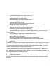
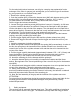
Adjusting the Single-Action trigger weight Simultaneously Left side - hold the trigger spring stud screw Right side - loosen the secondary side screw, then adjust the trigger spring stud screw slightly and retighten the right side clamp screw. 3.3 Trigger stop The travel way of the trigger in the Single-Action mode is stopped by an adjustable trigger stop screw. This screw is located in the trigger guard behind the trigger. The protruding length of the trigger stop screw can be varied with the included .
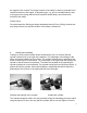
Adjusting the trigger stop screw 4. Double-Action function In this mode, the hammer is cocked by pulling the trigger. The maximum trigger weight is 158.6oz (4500g = 44.15N). Rimfire weapons can have a slightly higher trigger weight. Please notice! During DA-(Double Action) mode, it is absolutely necessary that the trigger reaches its foremost position before you pull the trigger again.
For the technically trained customer, we will give a step-by-step explanation for the exchange of the roller. In general, we would prefer you to have this type of work done by your gunsmith or our certified Factory staff. 1. Remove the cylinder and grips. 2. Cock the hammer (#35), connect the hammer strut (#40) with hammer spring guide housing (#43). Use a hardened pin with a diameter of approx. .047" (1.2mm). For later models, the included .059"(1.5mm) Allen screw can be used.
the trigger is fully cocked. The proper function of the safety is directly connected to the correct movement of the trigger. A delayed trigger, e.g. due to a contamination or due to a trigger return spring that has been tensioned insufficiently, can influence the function of the safety. Please notice : Do not decrease the SA-trigger weight remarkably below 35.2oz (1000g), because not only the pre-travel, but also the function of the safety is influenced. 6.
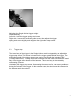
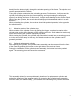
hand (from the bottom right), through the window opening of the frame. The ejection rod can be operated with the thumb. Fixing the cylinder accelerates the unloading process. Furthermore, it will prevent the cylinder from falling back into the frame opening, and ergo keeping the employed ejector from hitting the frame. If this occurs, it might cause damage to the surface finish. While fixing the cylinder, the muzzle should always point downwards and/or in a safe direction.
Unloading the cylinder 7. Interchangeable cylinder The barrel material used for the weapons with interchangeable cylinders depends on the law restrictions for the nominal caliber. Precision losses due to compromises are not to be expected. Occasionally, minor changes in the position of the point of aim in both calibers may occur. This problem can be overcome easily by selecting the right ammunition or by adjusting the sights. The revolver in caliber .
Please be aware that a remaking of an interchangeable cylinder results in additional work and thus in additional expenses compared to the serial production. 8. Sight systems All our revolver models have elevation and windage adjustable sights. The adjustments are carried out by means of a screwdriver. Sights Model Combat / Model Sport / Model Target 8.1 Model Combat 8.1.1 Elevation adjustment A screw is inserted in the vertical axis of the sight, which can be accessed from the upper part of the sight.
When shooting left, the left screw has to be loosened (counter-clockwise) and the right side screw has to be tightened. When shooting to the right, the adjustment has to be done in the opposite order. 8.2 Model Sport 8.2.1 Elevation adjustment Elevation adjustment occurs via the elevation adjustment screw located in the sight. The elevation adjustment has a micrometer-click system. The elevation change of the sight is .0016"(.042mm) per click.
If your weapon is equipped with exchangeable rear sight blades, the elevation- and windage adjustment can be done by hand. This can also be facilitated by the use of a coin. A slight pressure on the upper side of the sight, done by e.g. the thumb, can relieve the elevation adjustment screw during this slight adjustment. The windage adjustment screw is located on the left side. Elevation and windage adjustment are effectively influenced by means of a micrometer-click screw. The sight physically moves .
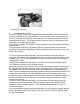
If your weapon is equipped with an exchangeable front sight system, you have the option to change different front sights. Beyond the standard equipment, you can additionally order individually shaped sights. The exchangeable front sights are installed via an Allen screw located at the muzzle of the barrel. The screw in the barrel rib is unscrewed by approximately .158" (4mm) with the included .059" (1.5mm) Allen wrench. Then, the front sight can be taken out of the rib.
The barrel weight is installed underneath the barrel, by pushing it from the front at the bottom of the barrel shroud. However before attempting this, the attaching screws have to be backed off. The barrel shroud, as well as the surface of attachment have to be free of oil. To avoid damage of the barrel shroud, any dirt has to be removed. Then, the barrel weight can be pushed on the barrel shroud.
The action and all other movable elements should be oiled. Besides cleaning the functional parts, the surface of the weapon has to be cleaned and oiled as well. When using spray oil, a take down of the weapon is not necessary. Only use modern, water-impenetrable weapon oils with a low viscosity. Dirt can cause malfunctioning of the weapon. Avoid this by cleaning your weapon frequently and carefully. For example: Remaining dirt like unburned powder can easily get underneath the ejector during unloading.
our weapons has been proven worldwide in numerous tests. In addition to the construction features of the weapon and the exact manufacturing tolerances, the shooting performance is also determined by the ammunition employed. In order to give a statistically covered statement of the shooting performance of our weapon, numerous test series need to be performed. Single shooting results are therefore subjective. For this reason, we abstain from including an original target. 13.
15. 1. 2. 2.1 2.2 2.3 2.4 2.5 2.6 2.7 3. 4. 5. 5.1 6. 7. 8. 9. 10. 11. 12. 13. 14. 15. 16. 17. 18. 19. 20. 21. 22. 23. 24.
25. Trigger wind-up spring 26. Trigger 27. Cylinder stop 28. Pin for cylinder stop 29. Transporter 30. Double action roller* 31. Guide pin for transporter and double action roller 32. “V” spring for transporter 33. Hammer cocking cam 34. Retaining pin for #33 35. Hammer complete with axle 36. Hammer lifter 37. Compression spring for #36 38. Retaining pin for #36 39. Pin for #40 40. Hammer strut 41. Bushing for hammer spring 42. Hammer spring* 43. Hammer spring guide housing 44. Cylinder release lever 45.
58. 59. Leaf spring for rear sight notch Cylinder locking plunger with retaining pin 60. Compression spring for cylinder locking bolt 61. Locking bolt for cylinder lock 62. Retaining pin with compression spring for #61 63. Trigger attaching screw 64. Side-plate screw 64.1 Fitted pin for side-plate 65. Lower retaining pin for grips 65.1 Single retaining pin for Match grip 65.2 Upper retaining pin for grips 66. Trigger stop screw 67. Grips* 68. Grip screws (pair) 69. Grip screw bushings (pair) 70.
Revolver in Parts 21
Additional info / Warnings KORTH“Raw steel transformed into precision” In the world of first-class firearms, the name “KORTH” is synonymous with precision. This is a direct result of employing only specially selected materials coupled with skilled labor. This policy guarantees superior shooting performance as well as extremely long weapon life. The KORTH double action revolver is “THE” weapon for demanding marksmen.
largest diameter and is factory installed in the weapon. This results in an absolutely soft double action. From #2 to #1, in that descending order, the pressure point becomes harder. Rollers #2 and #1 are supplied with the revolver, together with an allen wrench in order to adjust the trigger stop screw. By changing the rollers, the marksman is able to effect differentiation to, and adjustment of the trigger pull in accordance with his / her own ideas and existing circumstances.
Trigger pull: The KORTH revolver is factory adjusted with a single action trigger pull of 49.34oz (1400g). By means of the trigger pull adjustment, the marksman is infinitely capable of adjusting this tension within the parameter range of 35.24 - 88.11oz (1000 - 2500g). Single Action Only: By special request, revolvers can be ordered with Single Action Only function. This revolver, when constructed and delivered, will have no double action capability.
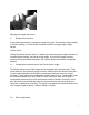
barrel can easily be removed after shooting by means of a nylon or a brass brush with the employment of Kleen-Bore 3n1. Soaking stubborn areas may be necessary. Try to use only jacketed ammo if possible, as this will reduce lead build-up. Do not use a bronze or stainless brush for the purpose of cleaning the barrel as this will scratch / damage the polished bore. Always remove the grips when thoroughly cleaning your weapon.
to create a glare-free line of sight. A milled front sight is installed and all parts are sandblasted to provide a matte finish. Sight adjustment: When performing the elevation adjustment, it is advisable to loosen one of the side retaining screws. This will alleviate the side tension and facilitate the adjustment. After making the desired adjustment, the previously loosened side retaining screw must be re-tightened. Windage adjustment is effected via the two side retaining screws.
You must understand that it is impossible to make this firearm absolutely safe from firing under every and all circumstances when it is in a loaded condition. This risk can be greatly diminished or eliminated by simply keeping your firearm unloaded until you are actually ready to shoot. Like any other complex item, a firearm can be damaged or broken by abuse, such as dropping it on a hard surface.
A copy of the owners manual for your firearm is available from Korth Germany GmbH, Robert-Bosch-Strasse 11, D-23909 Ratzeburg, Germany.