
Manual


7
For the technically trained customer, we will give a step-by-step explanation for the
exchange of the roller. In general, we would prefer you to have this type of work done
by your gunsmith or our certified Factory staff.
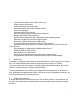
1. Remove the cylinder and grips.
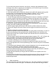
2. Cock the hammer (#35), connect the hammer strut (#40) with hammer spring guide
housing (#43). Use a hardened pin with a diameter of approx. .047" (1.2mm).
For later models, the included .059"(1.5mm) Allen screw can be used.
Pull the trigger and release the hammer.
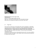
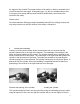
3. Loosen the trigger attaching screw (#63) but don’t remove it. Normally, six full turns
in counter-clockwise direction are sufficient. Remove the fitted pin for the side-plate.
Lift the side-plate on the left side of the weapon. The side-plate has to be lifted with a
screw-driver carefully. Please note that the tool is only inserted between the frame and
the side plate. The tool should not be pried against any action parts.
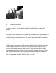
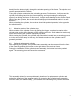
4. Remove the hammer spring assembly (#40-43), the transporter, and the hammer
cocking cam (#33) including the holding pins.
5. Pull the trigger slightly and lift up the bolt and the cylinder release lever (#44).
6. Remove the trigger roller with forceps from the trigger and insert the roller of your
choice.
7. Insert the transporter including guide pins.
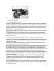
8. Install the cylinder release lever (#44) with the spring (#46) concomitantly. In order to
do this, the spring has to be inserted into the cylinder release lever, then has to be
rested in the cut-out of the cylinder release lever and then has to be inserted into the
cut-out of the frame.
9. Pull the trigger carefully backwards (approximately between .079 -.118" (2-3mm) and
insert the hammer. Please notice that the hammer complete with axle has to be
inserted not only in the release lever but also into the cut-out of the frame.
10. Insert the retaining pin for the hammer with the guide pin.
11. Insert the hammer spring unit carefully in between the hammer and the frame
anchor. Be cognizant of the correct positioning of the cut-out for the pin for the hammer
strut (#39).
12. Insert and install side plate with the external transporter lever to be pushed into the
cut-out of the side plate. Tighten the side plate and trigger screw.
13. Slowly cock the hammer. After putting pressure on the hammer spring, the
previously installed arresting pin can be removed. In this way, the hammer is retained
and slowly de-cocked after removal of the arresting pin.
14. Now, the final assembly of the grip and the insertion of the cylinder can occur.
ATTENTION !
Do not perform a functional test during the mounting process. We are not liable for the
mounting process and for consequential damages if not performed by Factory
authorized personnel.
5. Safety equipment
The revolver has an automatic hammer drop lever. This safety prohibits an intentional
hit of the hammer onto the firing pin. The hammer can only reach the firing pin when