MS2010 OWNER’S MANUAL Mobile Audio System • PLL Synthesizer Stereo Radio • Digital Compact Disc Player • Automatic Memory Storing • Full Detachable Panel • Preset Equalization • Electronic Shockproof (ESP) Function • Remote Control
CONTENTS Installation ...........................................3 Playing all tracks in random..............12 Take out screw before installation.........3 Ejecting a disc ..................................12 DIN Rear-Mount (Method A) .................3 Disc notes ...........................................12 DIN Front-Mount (Method B) ................4 Remote Control Handset..................13 Installing the unit ...................................4 Specification.................................
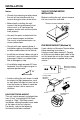
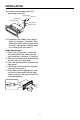
INSTALLATION Notes: TAKE OUT SCREWS BEFORE INSTALLATION • Choose the mounting location where the unit will not interfere with the normal driving function of the driver. Before installing the unit, please remove the two screws as indicated. Take out screws before installation • Before finally installing the unit, connect the wiring temporarily and make sure it is all connected up properly and the unit and the system work properly. • Use only the parts included with the unit to ensure proper installation.
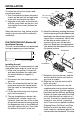
INSTALLATION To fasten the unit to the factory radio mounting brackets: 1. Use a screwdriver to loosen the hook's screws on the front left and right sides of the unit and remove the hooks. 2. Align the screw holes on the bracket with the screw holes on the unit, and then tighten the screws (5x5mm) on each side. Sleeve L Key Outer Trim Ring Front Panel R Key Note: the outer trim ring, sleeve and the metal strap are not used for method A installation. 6.
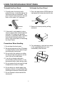
INSTALLATION also helps ensure proper electrical grounding of the unit. Spring Washer Hex Nut Metal Strap Mounting Bolt Plain Washer Tapping Screw 10. Reconnect the cable to the vehicle battery's negative (-) terminal. Then replace the outer trim ring and install the unit's front panel. (see the steps of “installing the front panel”). Removing the unit 1. Make sure the ignition is turned off, then disconnect the cable from the vehicle battery's negative (-) terminal. 2.
USING THE DETACHABLE FRONT PANEL To Install the Front Panel To Detach the Front Panel 1. Carefully open the front panel’s protective case. Insert the right of the front panel into the radio body. Then press the left side into place. You will hear a click when it is in position. 1. Press the open button (OPEN) and the front panel will release on the left side. Open 2. Remove the front panel by pulling outwards. 2.
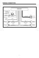
WIRING CONNECTION MAIN UNIT ANTENNA CONNECTOR IGNITION RED SWITCH (ACC+) MEMORY YELLOW BACK-UP (B+) GROUND (B–) BLACK 0.
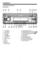
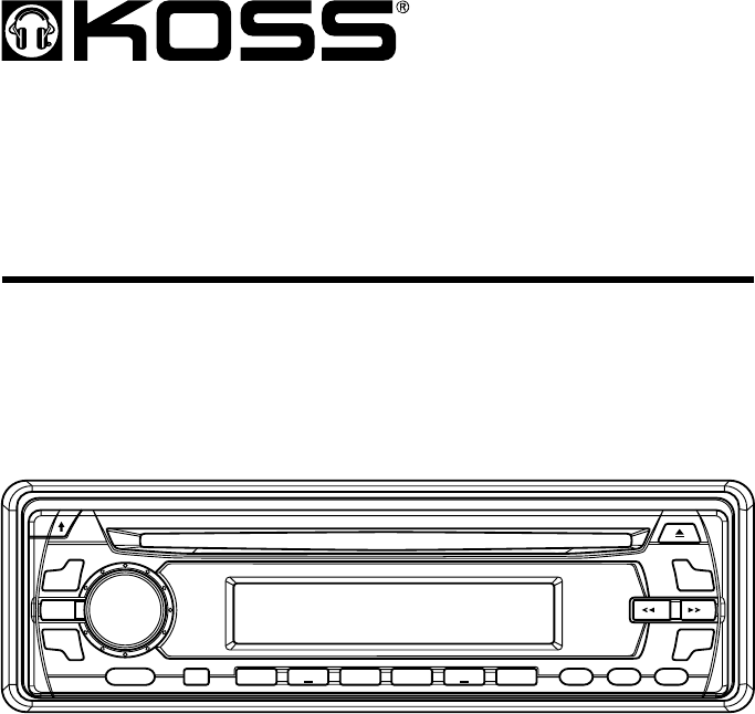
OPERATION LOCATION OF CONTROLS FRONT VIEW 19 7 11 10 15 9 1. 2. 3. 4. 5. 6. 7. 8. 9. 10. 11. 12. 13. 14. 5 18 20 21 8 24 22 14 23 15. 16. 17. 18. MON Button LOC Button MUT Button Eject ( ) Disc Slot MOD Button Open Button Display Power (PWR) SEL Volume Reset BND/LOU Preset Buttons 19. 20. 21. 22. 23. 24.
OPERATION LOCATION OF CONTROLS BACK VIEW 12 9
OPERATION SWITCHING THE UNIT ON/OFF Switch on the unit by pressing any button (except OPEN button (7) and button (4)). When system is on, press POWER button (9) to turn off the unit. MUTE Press MUT button (3) to mute the volume instantly. If any button is pressed while in the mute mode, the mute function is released. FACEPLATE RELEASE Press OPEN button (7) to detach the removable faceplate. EQUALIZATION Press EQ button (19) to turn on equalization function and to select desired audio mode.
OPERATION AUTO or MANUAL tuning mode to select the station you wish to enter into memory and then press and hold the M1 memory button (14) until the unit beeps to indicate the station has been stored into memory. Repeat this procedure for each of the remaining memory button positions (M2 to M6) and then move to the next band and repeat the procedure. • SELECTING THE FREQUENCY BAND In radio mode, press BND/LOU button (13) to select the desired band.
OPERATION • PLAYING ALL TRACKS IN RANDOM ORDER Press SHF button (23) to play all tracks on CD in random order. Press again to cancel the function. DISC NOTES: A. Notes on discs: 1. Attempting to use nonstandard shape discs (e.g. square, start, heart) may damage the unit. Be sure to use round shape CD discs only for this unit. 2. Do not stick paper or tape etc, onto the label side or the recording side of any discs, as it may cause a malfunction. 3.
REMOTE CONTROL HANDSET 1 7 4 3 8 9 6 5 13 2 12 10 11 14 15 FUNCTION KEYS & CONTROL 1. 2. 3. 4. 5. 6. 7. 8. 9. 10. 11. 12. 13. 14. 15.
SPECIFICATION GENERAL Power Supply Requirements Chassis Dimensions Tone Controls - Bass (at 100 Hz) - Treble (at 10 KHz) Maximum Output Power Current Drain : DC 12 Volts, Negative Ground : 178 (W) x 160 (D) x 50 (H) : : : : ± 10 dB ± 10 dB 4 x 15 Watts 15 Ampere (max.) CD PLAYER Signal to Noise Ratio Channel Separation Frequency Response : More than 55 dB : More than 45 dB : 40 Hz - 18 KHz RADIO FM 87.5 to 107.9 MHz 10.
TROUBLE SHOOTING Before going through the checklist, check wiring connection. If any of the problems persist after checklist has been made, consult your nearest service dealer. Symptom No power. If disc cannot be loaded or ejected. Cause Solution The car ignition switch is not on. If the power supply is connected to the car accessory circuits, but the engine is not running, switch the ignition key to “ACC”. The fuse is blown. Replace the fuse. Presence of CD disc inside the player.
Error Code showing on display Cause ERROR 1 Mechanism problem ERROR 2 Playback errors: Remedy Press “RESET” button. Dirty disc Clean the disc and load it as instruction manual mentioned. Disc is loaded up side down Load disc with label facing up. Disc is scratched Try another disc. Disc carries data which cannot be supported by the unit Try another disc.