
User's Manual


Doc2019_v1.4.0
9 / 22
MS- RA1xM Radar Module
MS-RA1xM Datasheet
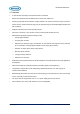
Figure 2. Blocks and Pin Descriptions
Pin 1: VCC
Power noise should be removed as much as possible to ensure normal analog operations of the radar
on a 3.3 V operating voltage.
Pin 2: GND
Pin 3: PWM or User I/O
The PWM is connected to the dedicated PWM port of the embedded MCU, and thus can be used as a
dimming control port for LED lighting. If the pin 3 is not used as a PWM port, it can be used as a general-
purpose I/O.
Pin 4: nReset
Low active reset signal
Pin 5: Motion Out
Motion detection signal output detected by the radar. A motion output signal is produced when motion
is detected within the motion detection range set by a user.
24GHz
Patch
Antenna
(TX)
Power
&
Filter
Radar
Controller
24GHz
Patch
Antenna
(RX)
AMP
&
Filter
MCU
(DSP)
Pin1: VCC (3.3V)
Pin2: GND)
Pin3: PWM or
USER I/O
Pin4: nReset
Pin5: Motion Out
Pin6: User I/O 1
Pin7: User I/O 2
Pin8: Velocity Out
Pin9: Rx (comm.)
Pin10: Tx (comm.)