CAT5 SWITCHER KE811CT(w-type) Instruction Manual Thank you for your purchase of this product Please be sure to read this manual completely prior to usage of this product. Ver 1.
RGB Interface Cable Use of a RGB interface cable longer than 3 m (9.84 feet) is not recommended. For U.S.A NOTE: This equipment has been tested and found to comply with the limits for a Class A digital device, pursuant to Part 15 of the FCC Rules. These limits are designed to provide reasonable protection against harmful interference when the equipment is operated in a commercial environment.
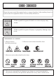
Usage Cautions Please be sure to read this manual prior to usage of product. After reading, keep it in a place near the equipment where it can be easily referred to. Warning ・If this symbol is ignored death or serious injury may occur. Caution ・If this symbol is ignored injury or property damage may occur. Explanation of symbols ● Shows caution (including warning) General caution ● Shows an action that should be done.
Warning ◆Do not continue to use this product if any of the following occurs : ※It may cause fire or electric shock. ・If you smell a strange odor or smoke. ・If water or a foreign object gets inside the product. ・After dropping the product. ・If the power cord is damaged. (exposure of core cable, severed cable) ◆If any of the above should occur immediately turn the power off and unplug the power cord. Contact the manufacturer or dealer who installed this product for repair.
Caution ◆Do not put this product in the following places. ※May cause fire or electric shock. ・Places where there is a lot of humidity or dust. ・Places where there is steam. ・Near places which generate heat. ・Places where water may come into contact with the product. ◆Turn off the power and follow all instructions , when connecting this product to other devices. ※Failure to use the recommended cables may cause generation of heat or fire. ◆Do not cover the ventilation holes.
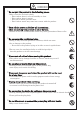
Index 1. About this product 1-1. Product and accessories 1-2. General information 2. The name and function of each parts 1 1 2 3 2-1. Front panel 3 2-2. Rear panel 5 3. Connection 7 3-1. The cautions and warnings 7 3-2. Preparation of a cable 8 3-3. Cable mounting kit and rack mounting kit 9 3-4. How to connect 4. Operation 10 12 4-1. The setting of front dip switch 12 4-2. The setting of bottom dip switch 13 4-3. Operation of buttons 14 5. Serial interface 15 5-1.
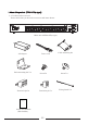
1.About this product (KE811CT(w-type)) 1-1. Product and accessories Please check that you have the accesories and items shown.
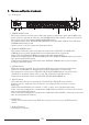
1-2 General Information This product, KE811CT(w-type), is a transmitter for long distance transmission of one line selected from RGB video, component video or composite video through a twisted pair cable (CAT5e or CAT6). In addition to video , one line of audio (stereo) , and serial command (*1) can be transmitted through a serial port. By INPUT switch, it is possible to control PDP or projector at the same time as switching of video and audio . (*1) Beforehand registered serial command is transmitted.
2. The name and function of each parts 2-1. Front panel ⑨ 22 KE811CT CAT5 OUT OPTION INPUT SERIAL 3 AUDIO IN8 POWER CONT ① DISPLAY POWER A ② ⑩ B C D E F 1 2 3 4 5 6 7 8 OFF SUB OUT ③ ④ 1 ⑤ ⑥ ⑦ ⑧ 4 RGB IN8 ⑭ ⑪ ① POWER CONT button This button controls external power. When this button is pushed,the signal (photo MOS relay make contact)is output from connector for POWER CONT. (This button is not for the product.) This button can be synchronized DISPLAY POWER button.
⑦ CAT5_OUT button CAT5 output is selected. ⑧ Front Dip Switch Please refer to "4-1. The setting of front dip switch." ⑨ SERIAL_3 DB9 connector for serial communication. This connector is used to register commands into the product. (Please refer to "5-2 Connection of RS232C cable.") ⑩ Front LED Yellow LED : It does not light. Green LED : It lights when command mode is ON. Orange LED : It lights when SERIAL1&3 are transmitting or receiving. ⑪ Bottom dip switch Option setting is available,etc...
2-2.Rear panel 22 21 AUDIO IN 1 3 2 4 3 2 1 5 5 6 23 7 6 7 24 25 SERIAL 1 SERIAL 2 26 CAT5 OUT1 AUDIO SUB OUT 4 CAT5 OUT2 PARALLEL REMOTE COMPOSITE SUB OUT COMPOSITE IN ⑫ ⑬ RGB IN COMPONENT IN ⑭ ⑮ RGB SUB OUT ⑯ A ⑰ B C D DC16V IN E F ⑱ ⑲ ⑳ ⑫ COMPOSITE IN 1-3 RCA connector, video input connectors. Input connectors for composite video. These connectors are corresponding to INPUT 1-3 at front panel. ※Please use a cable under 3m(9.84feet) in length when connecting.
⑲ DC16V_IN Connecter for power input. DC16V AC adapter is connected. ◆Warning The enclosed AC adapter must be used for this product. ⑳ FG The screw for frame ground. 21 22 AUDIO IN 1-4 RCA connector for audio input connector. These connectors are audio input connector. These connectors are corresponding to INPUT 1-4 at front panel. ※Please use a cable under 3m(9.84feet) in length when connecting. AUDIO IN 5-8 Mini-jack for audio input. These connectors are for audio input.
3. Connection 3-1.The cautions and warnings ◆Cautions ・ Use the recommended a twisted-pair cable for this product for best results. (OKANO ELECTRIC WIRE CO.,LTD: OKTP-E5-P-AWG 24x4P) When a cable other than the recommended cable is used, make sure that the characterisitcs and functionality of the cable is fully understood before use. ・When cable length is longer than the recommendation distance indicated in the "1-2 General information", quality of the image may deteriorate.
3-2.Preparation of a cable A CAT5e or CAT6 cable is used to connect this product and twisted pair receiver. This product and receiver are connected straight through as shown in the diagram below. ※ Please keep the combination of the pair lines as follows. If the combination of a pair line is incorrectly installed , there is a possibility that the quality of the image may deteriorate.
3-3. Cable mounting kit and rack mounting kit A mounting kit for the twisted-pair cable is enclosed with this product. Use the following diagram to attach the mounting kit.
3-4. How to connect Connect this product according to the following procedures. Ⅰ.Check that all of the devices ,PDP(Plasma Display Panel), video player, DVD player, PC, display, and so on, to connect are turned off. Ⅱ. Refer to the following diagrams when connecting cables to this product.
d).Audio 5 4 3 2 1 6 7 8(Front panel) AUDIO IN input input L R AUDIO SUB OUT input input L R input input L R Connector input input L R Mini-jack for audio input Connector 22 21 output output L R Audio output Connector 23 (for SUB OUT) Ⅲ.As for connection of cables going to twisted pair receiver, please refer to the manual of twisted pair receiver. Ⅳ.Connect between this product and twisted pair receiver by using CAT5e or CAT6 cable. (Please refer to "3-2 Preparation of cable.
4. Operation 4-1. The setting of front dip switch GH ON 1 NO. 2 3 4 1 ON :Registration mode (Regardless of the setting of No.2-4.) OFF:Standard mode 2 no working 3 ON :POWER CONT becomes ON, when AC adapter is connected to outlet. OFF:POWER CONT becomes ON, when POWER CONT is pressed. 4 no working ※ All switches of front dip switch are set at OFF as initial setting.
4-2. The setting of bottom dip switch 1 2 3 4 5 6 7 8 OFF NO.
4-3. Operation of buttons a) POWER CONT button It can control the power in the rack. The operation of others buttons can be controlled (become ON), when this button is pressed. When NO.7 of bottom dip switch is ON, DISPLAY POWER button synchronizes and becomes ON. (Please refer to "4-2. The setting of bottom dip switch.") When POWER CONT button is OFF, all buttons are OFF (It is not related to a setup of a switch). ※ This button is not for this product, this product is ON when AC adapter is connected.
5. Serial interface 5-1. The setting of personal computer Set the personal computer as follows, when this product is controlled.
5-2. Connection of RS232C cable Serial 1 & 3 Pin-Out Diagram Pin1 Pin2 Pin3 Pin4 Pin5 Pin6 Pin7 Pin8 Pin9 Non connect (NC) Transmitted (TX) Received Data (RD) DTE ready connected with Pin6. GND DCE ready Request to send (RTS) Clear to send (CTS) Non connect (NC) Serial 2 Pin-Out Diagram Pin1 Pin2 Pin3 Pin4 Pin5 Pin6 Pin7 Pin8 Pin9 Non connect (NC) Received Data (RD) Transmitted Data (TD) DTE. GND It connects with Pin4. It connects with Pin8. It connects with Pin7.
5-3. Control and registration method 5-3-1.
※ When OPTION button is used as alternate, control command can transmit ON/OFF registration command. When OPTION button is used as momentary, control command can transmit ON registration command only. ※ Memory size of control command is 32bytes (8 commands). The data length that can be sent at a time is 32bytes. If more than 32bytes data is transmitted, please send the data after answer-back is returned. If control command is transmitted before answer-back is returned, it may not be executed.
a) When controlling this product by sending one control command. This product can be controlled. Please send control command in the following order. 1. Character (input line or action select command). 2. Delimiter. 3. Character (output line select command). 4. Return. ※ Set the front dip switch to Registration mode. Please refer to "4-1 The setting of front dip switch." (Ex.1) input : IN2, output : CAT5 ASCII character representation B , 1 return HEX representation 42H 2CH 31H 0DH (Ex.
b) When controlling this product by sending control command consecutively. This product can be controlled. 8 control commands can be sent consecutively. Please send control commands in the following order. 1. Character (selecting IN) 2. Delimiter (,) 3. Character (selecting OUT) 4. Delimiter (;) 5. Character (selecting IN) 6. Delimiter (,) 7. Character (selecting OUT) 8. Delimiter (;) ・ ・ ・ n−3. Character (selecting IN) n−2. Delimiter (,) n−1. Character (selecting OUT) n.
c) Reading data To read the data, the current state of this product can be understood. Sending 1. Character (reading data command) 2. Return Receiving 1. State of selection of CAT5 2. Delimiter (;) 3. State of selection of SUB 4. Return (Ex.1) When IN3 is selected for CAT5 OUT and IN4 is selected for SUB OUT. Sending ASCII Character representation W return HEX representation 57H 0DH Receiving ASCII Character representation HEX representation C 43H ; 3BH D 44H return 0DH (Ex.
6. Parallel interface This product can be controlled by connecting parallel interface. This product can be controlled as the same operation by front buttons.
7.Specifications 7-1.The Specifications of this product Model name Input signal Output signal Input connector Output connector Extension cable Video input and output Video frequency response Audio input level Audio output level Audio frequency response Control RS232C and Parallel I/O remote Tally I/O Operating temperature and humidity Power consumption Power (AC adapter) Dimensions Weight KE811CT(w-type) Video :RGB4system、Component1system、Composite:3system、Audio:8system Video:SUB output(RGB/component、
7-2. The specification of control system connectors 7-2-1.Contact output connectors for power control (POWER CONT) and option (OPTION A-F) button output POWER CONT OPTION OUT A B C E D F Relay specification relay (no polarity) relay (no polarity) Relay type : photo MOS relay, make contact Rating : maximum 50mA, less than AC/DC 24V Internal circuit is as follows. fuse varistor ◆Caution ・Do not supply more than AC/DC 24V.
7-2-2. Connector for tally output 25 4 3 2 1 26 50 PARALLEL REMOTE Connector pin No. 1-19 for output Connector pin No. 21-25 for GND Connector pin No. 26-30 DC5V Output type : open-collector. Pullup (internal 10KΩ, 5V connection) Rating : maximum 20mA, DC5V ◆Caution Do not exceed the rating. Please put register ,R, to protect overcurrent as follows. +5V R(≧50Ω) +5V R 2V MAX20mA 100Ω 10kΩ (KE811CT) (Connection equipment) (Ex.
7-2-3. Connector for parallel input 25 4 3 2 1 26 50 PARALLEL REMOTE Connector pin No. 31-49 for input Connector pin No. 21-25 GND Connector pin No. 26-30 DC5V Contact type : Non-voltage contact ※ Please use non-voltage contact by momentary switch (non-lock) or open-collector of transistor when parallel input is executed. Parallel remote connector GND 21 GND 25 31 32 49 Please input as following timing.
8.Trouble shooting Problem Reference Please check the following The video can't be ● Is the power of the connection equipment turned on ? ● Is the power adapter cable properly connected to seen AC100-240V line and this product ? ● Is the POWER CONT button of this product turned on? ● Is the CAT5e or CAT6 cable properly connected to OUT 1 or OUT2 of this product? ● Isn't unexpected fore applied to the CAT5e or CAT6 cable connected to OUT1 or OUT2 of this product ? ● Is the cable properly connected to the
Sound has noise ● Is the twisted pair cable near the AC line? It should be far from the line. ● Is there a source causing noise close to AC adapter of this product ? A noise filter should be used in case of noise.
B & 2006.4.14 ※ Design and specifications are subject to change without notice.