Kramer Electronics, Ltd.
Contents Contents 1 2 2.1 3 4 4.1 4.2 4.3 5 5.1 5.2 5.3 6 6.1 6.2 6.3 6.
Contents Tables Table 1: 707 Video Audio Line Transmitter Features Table 2: 708 Video Audio Line Receiver Features Table 3: 709 Y/C Line Transmitter Features Table 4: 710 Y/C Line Receiver Features Table 5: 711xl Video-Audio Line Transmitter Features Table 6: 712xl Video-Audio Line Receiver Features Table 7: 711xl/712xl LINE IN and LINE OUT Connector Pinout Table 8: Technical Specifications of the 707 and the 708 Table 9: Technical Specifications of the 709 and the 710 Table 10: Technical Specifications of
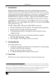
Introduction 1 Introduction Welcome to Kramer Electronics (since 1981): a world of unique, creative and affordable solutions to the infinite range of problems that confront the video, audio and presentation professional on a daily basis. In recent years, we have redesigned and upgraded most of our line, making the best even better! Our 500-plus different models now appear in 8 Groups1, which are clearly defined by function.
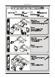
Getting Started 708 707 Display Video Player Amplifier 709 s-Video Camera 710 Display 712xl 711xl Display 2 Composite Video Source KRAMER: SIMPLE CREATIVE TECHNOLOGY
Overview 3 Overview This manual describes the: The 707 Video Audio Line Transmitter and the 708 Video Audio Line Receiver (see section 4) The 709 Y/C Line Transmitter and the 710 Y/C Line Receiver (see section 5) The 711xl Video-Audio Line Transmitter and the 712xl Video-Audio Line Receiver (see section 6) To achieve the best performance: Connect only good quality connection cables, thus avoiding interference, deterioration in signal quality due to poor matching, and elevated noiselevels (often associated
The 707 and 708 Video Audio Line Transmitter and Receiver 4 The 707 and 708 Video Audio Line Transmitter and Receiver This section describes: The 707 (see section 4.1) The 708 (see section 4.2) How to connect the 707/708 Video Audio Line Transmitter/Receiver (see section 4.3) The 707 and 708 are a twisted pair transmitter and receiver for composite video and unbalanced mono audio signals.
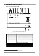
The 707 and 708 Video Audio Line Transmitter and Receiver 4.1 Your 707 Video Audio Line Transmitter Figure 1 and Table 1 define the 707: Figure 1: 707 Video Audio Line Transmitter Table 1: 707 Video Audio Line Transmitter Features # 1 2 3 4 5 6 7 Feature LINE OUT RJ-11 Connector AUDIO LEVEL Trimmer COND.
The 707 and 708 Video Audio Line Transmitter and Receiver 4.
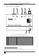
The 707 and 708 Video Audio Line Transmitter and Receiver 4.3 Connecting the 707/708 Video Audio Line Transmitter/Receiver You can use the 707 and 708 to configure a video audio line transmitter and receiver system. To connect the 707 Video Audio Line Transmitter with the 708 Video Audio Line Receiver, as illustrated in the example in Figure 3, do the following: 1. Connect a composite video source (for example, a video player) to the VIDEO IN BNC connector of the 707. 2.
The 707 and 708 Video Audio Line Transmitter and Receiver 708 707 Display Video Player Amplifier Figure 3: Connecting the 707/708 Video Audio Line Transmitter/Receiver System 8 KRAMER: SIMPLE CREATIVE TECHNOLOGY
The 709 and 710 Y/C Line Transmitter and Receiver 5 The 709 and 710 Y/C Line Transmitter and Receiver This section describes: The 709 (see section 5.1) The 710 (see section 5.2) How to connect the 709/710 Video-Audio Line Transmitter/Receiver (see section 5.3) The 709 and 710 are a twisted pair transmitter and receiver for s-Video (Y/C) signals.
The 709 and 710 Y/C Line Transmitter and Receiver 5.1 Your 709 Y/C Line Transmitter Figure 4 and Table 3 define the 709: Figure 4: 709 Y/C Line Transmitter Table 3: 709 Y/C Line Transmitter Features # 1 2 3 4 5 6 7 Feature C OUT, Y OUT Terminal Block Connector Y GAIN Trimmer Y EQ.
The 709 and 710 Y/C Line Transmitter and Receiver 5.2 Your 710 Video-Audio Line Receiver Figure 5 and Table 4 define the 710: Figure 5: 710 Y/C Line Receiver Table 4: 710 Y/C Line Receiver Features # 1 2 3 4 5 6 7 8 Feature Y/C OUTPUT 4p Connector Y EQ.
The 709 and 710 Y/C Line Transmitter and Receiver 5.3 Connecting the 709/710 Y/C Line Transmitter/Receiver You can use the 709 and 710 to configure a Y/C Transmitter and Receiver system. To connect the 709 Y/C Line Transmitter with the 710 Y/C Line Receiver, as illustrated in the example in Figure 6, do the following: 1. Connect an s-Video source (for example, an s-Video camera) to the Y/C INPUT 4p connector on the 709. 2.
The 709 and 710 Y/C Line Transmitter and Receiver s-Video Camera Display Figure 6: Connecting the 709/710 Y/C Line Transmitter / Receiver System From the C OUT Y OUT terminal block connector of the 709 unit To the C IN Y IN Terminal block connector of an additional 710 unit Figure 7: Connecting an Additional 710 Unit 13
The 711xl and 712xl Video-Audio Line Transmitter and Receiver 6 The 711xl and 712xl Video-Audio Line Transmitter and Receiver This section: Describes the 711xl (see section 6.1) Describes the 712xl (see section 6.2) Defines the 6-pole detachable terminal block connector pinout (see section 6.3) Describes how to connect the 711xl/712xl Video-Audio Line Transmitter/Receiver (see section 6.
The 711xl and 712xl Video-Audio Line Transmitter and Receiver 6.
The 711xl and 712xl Video-Audio Line Transmitter and Receiver 6.
The 711xl and 712xl Video-Audio Line Transmitter and Receiver 6.3 The 6-pole Detachable Terminal Block Connector Pinout Table 7 defines the LINE IN and LINE OUT connector pinout: Table 7: 711xl/712xl LINE IN and LINE OUT Connector Pinout PIN 1 2 3 4 5 6 Function Audio R+ Audio RAudio L+ Audio LVideo + Video - 6.4 Connecting the 711xl and the 712xl You can use the 711xl and 712xl to configure a Video-Audio Transmitter and Receiver system.
The 711xl and 712xl Video-Audio Line Transmitter and Receiver Display Composite Video Source Figure 10: Connecting the 711xl/712xl From the LINE OUT terminal block connector of the 711xl unit To the LINE IN Terminal block connector of an additional 712xl unit Figure 11: Connecting an Additional 712xl Unit 18 KRAMER: SIMPLE CREATIVE TECHNOLOGY
Technical Specifications 7 Technical Specifications1 In this section: Table 8 includes the technical specifications of the 707 and the 708 Table 9 includes the technical specifications of the 709 and the 710 Table 10 includes the technical specifications of the 711xl, and the 712xl Table 8: Technical Specifications of the 707 and the 708 INPUTS: OUTPUTS: BANDWIDTH: NON-LINEARITY: DIFF. GAIN: DIFF.
Technical Specifications Table 9: Technical Specifications of the 709 and the 710 INPUTS: OUTPUTS: BANDWIDTH: NON-LINEARITY: DIFF. GAIN: K-FACTOR: S/N RATIO: CONTROLS: POWER SOURCE: DIMENSIONS: WEIGHT: ACCESSORIES: OPTIONS: 709 710 s-Video, 1Vpp/75 (Y), 0.3Vpp/75 (C) 4-pin terminal block on a 4p connector 4-pin terminal block s-Video, 1-Vpp/75 (Y), 0.3Vpp/75 (C) on a 4p connector 8.4MHz, (Y) at 100m 0.07% 0.04% 1.4% at 100m Better than 60dB Y gain: -2.4dB to +6.5dB; Y EQ: -2.7dB to 15.6dB; C gain: -5.
LIMITED WARRANTY Kramer Electronics (hereafter Kramer) warrants this product free from defects in material and workmanship under the following terms. HOW LONG IS THE WARRANTY Labor and parts are warranted for seven years from the date of the first customer purchase. WHO IS PROTECTED? Only the first purchase customer may enforce this warranty. WHAT IS COVERED AND WHAT IS NOT COVERED Except as below, this warranty covers all defects in material or workmanship in this product.
For the latest information on our products and a list of Kramer distributors, visit our Web site: www.kramerelectronics.com, where updates to this user manual may be found. We welcome your questions, comments and feedback. Safety Warning: Disconnect the unit from the power supply before opening/servicing. Caution Kramer Electronics, Ltd. Web site: www.kramerelectronics.com E-mail: info@kramerel.