Kramer Electronics, Ltd.
Contents Contents 1 2 2.1 3 3.1 3.2 4 4.1 4.2 5 5.1 5.
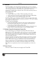
Introduction 1 Introduction Welcome to Kramer Electronics! Since 1981, Kramer Electronics has been providing a world of unique, creative and affordable solutions to the vast range of problems that confront the video, audio, presentation, and broadcasting professional on a daily basis. In recent years, we have redesigned and upgraded most of our line, making the best even better! Our 1,000-plus different models now appear in 11 groups 1 that are clearly defined by function.
Getting Started 2 Getting Started We recommend that you: • Unpack the equipment carefully and save the original box and packaging materials for possible future shipment • Review the contents of this user manual • Use Kramer high performance, high resolution cables 1 2.1 Quick Start This quick start chart summarizes the basic setup and operation steps. 1 The complete list of Kramer cables is available from http://www.kramerelectronics.
Overview 3 Overview The 713 and 714 are a TP (Twisted Pair) transmitter and receiver for composite video and unbalanced stereo audio signals. The 713 transmitter converts composite video and stereo audio into a Twisted Pair (TP) signal and the 714 receiver converts the TP signal back to composite video, stereo audio and also provides an S/PDIF digital audio output.
Defining the 713/714 Video-Audio Line Transmitter/Receiver 4 Defining the 713/714 Video-Audio Line Transmitter/Receiver This section defines the: • 713 Video-Audio Line Transmitter (see Section 4.1) • 714 Video-Audio Line Receiver (see Section 4.2) 4.1 Defining the 713 Video-Audio Line Transmitter Figure 1 and Table 1 define the front and rear panels of the 713 Video-Audio Line Transmitter.
Defining the 713/714 Video-Audio Line Transmitter/Receiver 4.2 Defining the 714 Video-Audio Line Receiver Figure 2 and Table 2 define the front and rear panels of the 714 Video-Audio Line Receiver. Figure 2: 714-05 Front and Rear Panels Table 2: 714-05/714-10/714-15 Front and Rear Panel Features 1 2 3 4 5 # 6 7 8 9 LINK LED Feature V LED A LED MANUAL EQ. Buttons + – AUTO EQ.
Defining the 713/714 Video-Audio Line Transmitter/Receiver Figure 3: 714-10 Video-Audio Line Receiver Front Panel Figure 4: 714-15 Video-Audio Line Receiver Front Panel 6 KRAMER: SIMPLE CREATIVE TECHNOLOGY
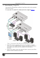
Connecting the 713 and 714 5 Connecting the 713 and 714 You can use the 713 and 714 to configure a long distance audio-video transmitter and receiver system. To connect the 713 and the 714 as illustrated in the example in Figure 5: Figure 5: Connecting the Video-Audio Line Transmitter/Receiver System 1.
Connecting the 713 and 714 3. On the 714, connect the VIDEO OUT BNC connector to a composite video acceptor (for example, a display), and connect the AUDIO OUT RIGHT and LEFT RCA connectors to an unbalanced audio acceptor (for example, an amplifier). 4. On the 714, connect the S/PDIF connector to a digital audio acceptor (for example, an amplifier). 5. Connect the 12V DC power adapters first to the 713 then to the 714. Note: This order of connection is mandatory. 6.
Connecting the 713 and 714 5.2 Wiring the CAT 5 LINE IN/LINE OUT RJ-45 Connectors Table 3 and Figure 6 define the CAT 5 pinout, using a straight pin-to-pin cable with RJ-45 connectors. When using STP cable, connect/solder the cable shield to the connector shield.
Technical Specifications 6 Technical Specifications Table 4 lists the technical specifications 1 of the 713 and the 714-05/714-10/714-15.
LIMITED WARRANTY Kramer Electronics (hereafter Kramer) warrants this product free from defects in material and workmanship under the following terms. HOW LONG IS THE WARRANTY Labor and parts are warranted for seven years from the date of the first customer purchase. WHO IS PROTECTED? Only the first purchase customer may enforce this warranty. WHAT IS COVERED AND WHAT IS NOT COVERED Except as below, this warranty covers all defects in material or workmanship in this product.
For the latest information on our products and a list of Kramer distributors visit www.kramerelectronics.com where updates to this user manual may be found. We welcome your questions, comments, and feedback. Safety Warning: Disconnect the unit from the power supply before opening/servicing. Caution Kramer Electronics, Ltd. Web site: www.kramerelectronics.com E-mail: info@kramerel.