K R A ME R E LE CT R O N IC S L TD .
Contents 1 Introduction 1 2 2.1 2.2 2.3 3 3.1 Getting Started Achieving the Best Performance Safety Instructions Recycling Kramer Products Overview Defining the 850 DisplayPort Pattern Generator 2 2 2 3 4 4 4 4.1 Connecting the 850 Connecting a PC 6 7 5 5.1 5.2 Operating the 850 Pattern Generator Operating the 850 Using the Front Panel Buttons Operating the 850 Using the Control Application 11 12 13 6 Technical Specifications 22 7 Communication Parameters 23 8 8.1 8.2 8.
1 Introduction Welcome to Kramer Electronics! Since 1981, Kramer Electronics has been providing a world of unique, creative, and affordable solutions to the vast range of problems that confront the video, audio, presentation, and broadcasting professional on a daily basis.
2 Getting Started We recommend that you: Unpack the equipment carefully and save the original box and packaging materials for possible future shipment i 2.1 Review the contents of this user manual Go to http://www.kramerelectronics.com/support/product_downloads.asp to check for up-to-date user manuals, application programs, and to check if firmware upgrades are available (where appropriate).
2.3 Recycling Kramer Products The Waste Electrical and Electronic Equipment (WEEE) Directive 2002/96/EC aims to reduce the amount of WEEE sent for disposal to landfill or incineration by requiring it to be collected and recycled. To comply with the WEEE Directive, Kramer Electronics has made arrangements with the European Advanced Recycling Network (EARN) and will cover any costs of treatment, recycling and recovery of waste Kramer Electronics branded equipment on arrival at the EARN facility.
3 Overview The 850 is a high performance, DisplayPort video test pattern generator. It can generate 32 preset patterns at 16 popular, predefined, computer and HD video resolutions and seven user-defined resolutions, including several unique patterns incorporating motion. In particular, the MultiTOOLS® 850 features: 3.
50 Front Panel Features # Feature Function 4 CS/ASF Press to select either the Color Space (when the ON/OFF button is on) or Audio Sample Frequency functions (when the ON/OFF button is off) 5 DELAY/ASD Press to select either the Delay (when the ON/OFF button is on) or Audio Sample Data functions (when the ON/OFF button is off) 6 2-digit 7-segment Display Indicates the current setting.
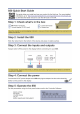
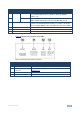
4 Connecting the 850 ! Always switch off the power to any device before connecting it to your 850. After connecting your 850, connect its power and then switch on the power to the device. To connect the 850 as illustrated in the example in Figure 3: 1. Connect the DP OUT connector to a DisplayPort acceptor (for example, a flat panel LCD display). 2. Optional—connect a PC to control the 850 via the RS-232 or USB port. 3. Connect the power adapter to the 5V DC socket and to the mains electricity.
4.1 Connecting a PC You can connect to the 850 via the RS-232 serial and via the USB port. 4.1.1 Connecting a PC via the RS-232 Serial Port You can connect to the 850 via an RS-232 connection using, for example, a PC. Note that a null-modem adapter/connection is not required.
8. After a few seconds the Found New Hardware message appears as shown in Figure 4. Figure 4: Found New Hardware Wizard Window 9. Click on the No, not this time radio button. 10. Click Next. 11. Select Install from a list or specific location (Advanced) as shown in Figure 5.
Figure 5: File Location Selection Window 12. Click Next. 13. Select Search for the best driver in these locations. 14. Check Include this location in the search. Browse to your previously designated folder. 15. Click Next. 16. Select the file atm6124.inf 17. The warning This driver is not digitally signed! appears. 18. Click Next. 19. Ignore the warning. Click Continue Anyway. 20. In the Insert disk window, click OK as shown in Figure 6.
Figure 6: Insert Disk Window 21. Select the file atm6124.sys and click Open. The driver installs and a success message is displayed. The USB driver has been successfully installed and you can install the 850 Control Application. 22. Navigate to the designated folder to which you downloaded the Control Application. 23. Double-click the file setup.exe from this folder or from the distribution media included with the 850. The Control Application has been successfully installed.
5 Operating the 850 Pattern Generator The 850 can be operated using the front panel buttons (see Section 5.1) and the 850 Control Application (see Section 5.2). The 850 Control Application is available as a free download from http://www.kramerelectronics.com). The following output video resolutions are supported.
The following video and audio output options are supported. Output Settings 5.
5.2 Operating the 850 Using the Control Application The 850 Control Application is a PC-based program which lets you program and control the device. To use the 850 Control Application you must download and install the USB driver and the 850 Control Application. Note: The USB driver is not supported by Windows 64 bit systems. 5.2.1 Connecting to the Device To connect to the device: 1. Run the Control Application by clicking Start > Programs > Kramer Electronics > 850. 2. Click the Connect button.
Note: If the drop-down list shows No USB Devices, then either you have not installed the USB driver (see Section 4.1.2) or the installation was not successful. 6. Click Connect. If the connection is not successful, a Timeout error message appears as shown in Figure 8. If the connection is successful, the main window shown in Figure 9 appears. Figure 8: Connection Error Message 5.2.2 Controller Software Main Window The Controller Software Main Window is shown in Figure 9.
Figure 9: Controller Software Main Window 850 Controller Software Main Window # Feature Function 1 Connect Button Press to connect to a device (see Section 5.2.
850 Controller Software Main Window # Feature Function 7 Status of Connected Device Information on the currently connected display 8 Status of Output Information on the currently selected output settings 9 EDID Info Click on Get EDID Info from the menu bar to display EDID information from the connected display.
5.2.
5.2.4 Editing User Defined Resolutions To edit a user defined resolution: 1. Click the required user defined resolution edit button . The User Defined Window appears with the CEA 861 Standard Tab selected as shown in Figure 12. Figure 12: User Defined Resolution Window–Standard Tab 2. In the Label field, enter the required label for the button. 3. Click one of the resolutions to select the required resolution. 4.
Figure 13: User Defined Resolution Advanced Window–Additional Tab 5. Select the required aspect ratio and resolution. 6. Click OK to save the additional parameters or click the Advanced button to edit the timing parameters and EDID values. The Advanced Window appears with the Timing Parameters tab selected as shown in Figure 14.
Figure 14: User Defined Resolution Advanced Window–Timing Parameters Tab 7. Edit or select the required resolution timing values, such as, Pixel Clock and Digital Sync. 8. Click OK to accept the changes or click on the EDID tab to edit the EDID values. The EDID tab is displayed as shown in Figure 15.
Figure 15: User Defined Resolution Advanced Window–EDID Tab 9. Edit the EDID values as required. 10. Click OK to save the values. 5.2.5 To Read EDID Information To read EDID information: Click Get EDID Info on the menu bar. The EDID of the display connected to the 850 is read and shown under EDID Info. If there is no display connected to the 850, random data is displayed, (see Figure 9).
6 Technical Specifications OUTPUT: 1 DisplayPort connector CONTROL: Five dual-function and two single function front panel buttons, Remote control via USB on a USB connector and RS-232 on a 9-pin D-sub connector POWER SOURCE: 5V DC, 670mA OPERATING TEMPERATURE: 0° to +40°C (32° to 104°F) STORAGE TEMPERATURE: -40° to +70°C (-40° to 158°F) HUMIDITY: 10% to 90%, RHL non-condensing DIMENSIONS: 10.7cm x 10.0cm x 4.4cm (4.2" x 3.9" x 1.7”) W, D, H WEIGHT: 0.4kg (0.88lbs) approx.
7 Communication Parameters RS-232 Baud Rate: 9600 Data Bits: 8 Stop Bits: 1 Parity: None 850 - Communication Parameters 23
8 Serial Protocol The 850 can be controlled via the serial port using the commands described in this section. 8.1 Command Format Commands must be in the following format: 0xEB, address, command, length of data, data 1,…, data n, checksum where the following table describes the command components. Command Component 0xEB address command length of data data 1, data n checksum 8.2 Description Fixed command start byte Device address. This is always 0x90 for the 850 Command to be sent (see Section 8.
8.3 Commands The commands listed below are supported by the 850. Note: The checksum is required at the end of the send/receive command as shown in Section 8.1. If a checksum is not included in a sent command, the device will not respond. 8.3.1 Get Device Address and Software Version Command 0x00 Send/Receive 0xEB, 0x00, 0x00, 0x01, 0xXX, checksum Data 0xXX can be any data except 0xEB 0xEB, [address], 0x00, 0x02, [version], 0x00, checksum 8.3.
8.3.4 Set Output Status Command 0xE6 Send/Receive 0xEB, address, 0xE6, 0x02, data1, data2, checksum 0xEB, address, 0xE6, 0x01, 0xFA, checksum 8.3.
8.3.
8.3.9 Set Detailed Timing for User-defined Resolution Command 0xEA Send/Receive 0xEB, address, 0xEA, 0x26, [block index], [perform immediately], data1H_4bits, data1L_4bits, data2H_4bits, data2L_4bits, ……, data17H_4bits, data17L_4bits, data18H_4bits, data18L_4bits, checksum 0xEB, address, 0xEA, 0x01, 0xFA, checksum Data 1. [block index]: From 0 to 7 Note: 7 is the preferred timing of the monitor, so it is preferable to use 0 to 6 2.
8.3.
For the latest information on our products and a list of Kramer distributors, visit our Web site where updates to this user manual may be found. We welcome your questions, comments, and feedback. Web site: www.kramerelectronics.com E-mail: info@kramerel.