K R A ME R E LE CT R O N IC S L TD .
Contents 1 Introduction 1 2 2.1 2.2 2.3 3 3.1 3.2 Getting Started Achieving the Best Performance Safety Instructions Recycling Kramer Products Overview Defining the VP-501N UXGA Scan Converter Input Resolutions 2 2 3 3 4 5 6 4 Connecting the VP-501N UXGA Scan Converter 7 5 5.1 5.2 5.3 5.4 5.5 5.
1 Introduction Welcome to Kramer Electronics! Since 1981, Kramer Electronics has been providing a world of unique, creative, and affordable solutions to the vast range of problems that confront video, audio, presentation, and broadcasting professionals on a daily basis.
2 Getting Started We recommend that you: Unpack the equipment carefully and save the original box and packaging materials for possible future shipment Review the contents of this user manual i 2.1 Go to http://www.kramerelectronics.com/support/product_downloads.asp to check for up-to-date user manuals, application programs, and to check if firmware upgrades are available (where appropriate).
2.2 Safety Instructions ! 2.3 Caution: There are no operator serviceable parts inside the unit Warning: Use only the Kramer Electronics input power wall adapter that is provided with the unit Warning: Disconnect the power and unplug the unit from the wall before installing Recycling Kramer Products The Waste Electrical and Electronic Equipment (WEEE) Directive 2002/96/EC aims to reduce the amount of WEEE sent for disposal to landfill or incineration by requiring it to be collected and recycled.
3 Overview The VP−501N is a scan converter for computer graphics and HDTV component video signals. It converts the input up to UXGA (1600x1200) and HDTV (1080p) to composite and s−Video (Y/C) signals simultaneously in either PAL or NTSC formats.
3.1 Defining the VP-501N UXGA Scan Converter Figure 1: VP-501N UXGA Scan Converter # 1 Feature 12V DC Power Connector Function +12V DC connector for powering the unit 2 Y/C OUT 4-pin Connector Connects to the s-Video acceptor 3 CV OUT BNC Connector Connects to the composite video acceptor 4 PAL/YUV DIP-switch Selects the video standard (OFF for PAL, ON for NTSC) and the color space standard (OFF for YUV, ON for RGB), see Section 5.
3.
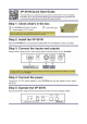
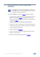
4 Connecting the VP-501N UXGA Scan Converter i Always switch OFF the power on each device before connecting it to your VP-501N. After connecting your VP-501N, connect its power and then switch on the power on each device. To connect the VP-501N, as the example in Figure 2 shows, do the following: 1.
Figure 2: Connecting a Computer Graphics Source to the VP-501N Figure 3: Connecting a High-Definition Source to the VP-501N 8 VP-501N - Connecting the VP-501N UXGA Scan Converter
5 Operating the VP-501N UXGA Scan Converter You can operate your VP-501N via the front panel buttons that function as: User-friendly front panel buttons for easy control of ProcAmp functions, flicker-reduction, image optimization, one-touch freezing, over-scanning and under-scanning Menu buttons: MENU, ENTER, – and +; or Quick-set buttons: FREEZE and OS/US (dual-purpose buttons) This section describes how to: 5.1 Use the quick-set buttons (see Section 5.
5.1.2 Using the OS/US Button Press the OS/US button to toggle between over-scan and under-scan: Over-scan omits the border.
5.3 Using the Menu Using the main menu, you can adjust the screen display (screen adjustments apply to both CV and Y/C displays). After pressing the MENU button (quick setbuttons are disabled), the main Menu (the menu times-out after 20 seconds of inactivity) appears on the screen. Use the menu buttons to scroll through the menu and make the required adjustments. Section 5.3.1 defines the menu items. 5.3.
Figure 5: Test Pattern Example You can set a test pattern to appear on the screen when there is no input connected to the VP-501N. To do so, enter the Advanced menu, select No Input and set a test pattern number. This test pattern will appear when there is no input connected. 5.5 Saving and Recalling The VP-501N lets you save and recall up to four setups (from 0 to 3). The Save mode stores all the menu settings in one of the four Save setup numbers.
5.5.
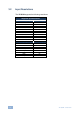
6 Technical Specifications INPUT: 1 x VGA/UXGA, analog component HD on an 15-pin HD connector OUTPUTS: 1 composite video 1Vpp/75 on a BNC connector 1 Y/C (s-Video) 1Vpp/75 (Y), 0.3Vpp/75 (C) on a 4-pin connector VGA up to UXGA; 480p, 576p, 720p, 1080p MAX.
For the latest information on our products and a list of Kramer distributors, visit our Web site where updates to this user manual may be found. We welcome your questions, comments, and feedback. Web site: www.kramerelectronics.com E-mail: info@kramerel.