K R A ME R E LE CT R O N IC S L T D .
Contents 1 Introduction 1 2 2.1 Getting Started Achieving the Best Performance 2 2 3 3.1 Overview Shielded Twisted Pair/Unshielded Twisted Pair 3 3 4 4.1 4.2 4.
1 Introduction Welcome to Kramer Electronics! Since 1981, Kramer Electronics has been providing a world of unique, creative, and affordable solutions to the vast range of problems that confront the video, audio, presentation, and broadcasting professional on a daily basis.
2 Getting Started We recommend that you: • Unpack the equipment carefully and save the original box and packaging materials for possible future shipment • Review the contents of this user manual • Use Kramer high-performance, high-resolution cables i 2.1 Go to http://www.kramerelectronics.com to check for up-to-date user manuals, application programs, and to check if firmware upgrades are available (where appropriate).
3 Overview The 717 and 718 are a twisted pair (TP) transmitter and receiver for composite video and unbalanced stereo audio signals. The 717 transmitter converts composite video and stereo audio into a twisted pair signal and the 718 receiver converts the twisted pair signal back to composite video and stereo audio.
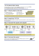
4 Defining the 717 and 718 This section defines the: 4.1 • 717 Video-Audio Line Transmitter (see Section 4.1) • 718 Video-Audio Line Receiver (see Section 4.2) Defining the 717 Video-Audio Line Transmitter Figure 1 defines the front and rear panels of the 717 Video-Audio Line Transmitter.
4.2 Defining the 718 Video-Audio Line Receiver Figure 2 defines the front and rear panels of the 718 Video-Audio Line Receiver for all models.
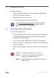
4.3 Wiring the TP LINE IN / LINE OUT RJ-45 Connectors This section defines the TP pinout, using a straight pin-to-pin cable with RJ-45 connectors. i Note, that the cable Ground shielding must be connected / soldered to the connector shield.
5 Connecting the 717 and 718 You can use the 717 and 718 to configure a long distance audio-video transmitter and receiver system. To connect the 717 and the 718 as illustrated in the example in Figure 4: 1. On the 717, connect a composite video source (for example, a composite video player) to the VIDEO IN BNC connector, and connect the unbalanced stereo audio to the AUDIO IN LEFT and RIGHT AUDIO IN RCA connectors. 2.
Figure 4: Connecting the Video-Audio Line Transmitter/Receiver System 8 717/718 - Connecting the 717 and 718
6 Technical Specifications 717 718-05 / 718-10 / 718-15 INPUTS: Video: 1 composite 1Vpp/75Ω on a BNC connector Audio: 1 stereo unbalanced audio 16Vpp/10kΩ on two RCA connectors 1 RJ-45 CAT 5 connector OUTPUTS: 1 RJ-45 CAT 5 connector Video: 1 composite 1Vpp/75Ω on a BNC connector Audio: 1 stereo unbalanced audio 16Vpp/5kΩ on two RCA connectors MAX. SIGNAL LEVEL*: Video: 1.45Vpp (terminated 75Ω), Audio: 20Vpp BANDWIDTH (–3dB) *: Video: 6.
For the latest information on our products and a list of Kramer distributors, visit our Web site where updates to this user manual may be found. We welcome your questions, comments, and feedback. Web site: www.kramerelectronics.com E-mail: info@kramerel.