
User manual


717/718 - Defining the 717 and 718 5
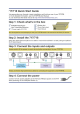
4.2 Defining the 718 Video-Audio Line Receiver
Figure 2 defines the front and rear panels of the 718 Video-Audio Line Receiver
for all models.
Figure 2: 718 Front and Rear Panels
# Feature Function
1 LINK LED Lights green when the connection is established
2 ON LED Lights green when the unit is powered on
3 VIDEO OUT BNC Connector Connects to the composite video acceptor
4 LINE IN RJ-45 Connector Connects to the LINE OUT RJ-45 connector on
the 717 using CAT 5 cable (see
Figure 2)
5 LEFT and RIGHT AUDIO OUT
RCA Connectors
Connect to the left and right channels of the
unbalanced stereo audio acceptor
6 12V DC Connector Connects to the 12V DC power supply