K R A ME R E LE CT R O N IC S L TD .
Contents 1 Introduction 1 2 2.1 2.2 2.3 3 3.1 Getting Started Achieving the Best Performance Safety Instructions Recycling Kramer Products Overview Defining the FC-41 HD-SDI to Component Converter 2 2 3 3 4 4 4 Installing in a Rack 7 5 5.1 6 6.1 6.
1 Introduction Welcome to Kramer Electronics! Since 1981, Kramer Electronics has been providing a world of unique, creative, and affordable solutions to the vast range of problems that confront video, audio, presentation, and broadcasting professionals on a daily basis.
2 Getting Started We recommend that you: Unpack the equipment carefully and save the original box and packaging materials for possible future shipment Review the contents of this user manual i 2.1 Go to http://www.kramerelectronics.com to check for up-to-date user manuals, application programs, and to check if firmware upgrades are available (where appropriate).
2.2 Safety Instructions ! 2.3 Caution: There are no operator serviceable parts inside the unit Warning: Use only the power cord that is supplied with the unit Warning: Do not open the unit.
3 Overview The Kramer FC-41 is a high performance converter for HD-SDI. It converts an HD-SDI input signal to component (Y, PB, PR) and RGB/HV signals.
FC-41 – Overview Figure 1: FC-41 HD-SDI to Component Converter Front Panel # Feature Function 1 POWER Switch Illuminated switch for turning the unit ON or OFF 2 SETUP / MENU LCD Display Displays the setup and the menu 3 MENU Button Press to open the menu (see Section 6.
6 Figure 2: FC-41 HD-SDI to Component Converter Rear Panel # Feature Function SDI IN BNC Connector Connects to the HD/SD SDI source 11 SDI BNC Connector Connects to the HD-SDI acceptor (the output is reclocked and equalized) 12 SDI BNC Connector Connects to the HD-SDI acceptor (the output is reclocked and equalized) 13 14 15 OUTPUTS 10 Y BNC Connector PB BNC Connector Connects to the component video acceptor PR BNC Connector 16 RGB/HV 15-pin HD Connector Connects to the RGB or RGBHV accep
4 Installing in a Rack This section provides instructions for rack mounting the unit.
5 Connecting the FC-41 i Always switch off the power to each device before connecting it to your FC-41. After connecting your FC-41, connect its power and then switch on the power to each device. To connect the FC-41, as illustrated in the example in Figure 3, do the following: 1. Connect the SDI source (for example, an HD-SDI Video player) to the SDI IN BNC connector. 2.
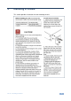
Figure 3: Connecting the FC-41 HD-SDI to Component Converter 5.1 Connecting to the FC-41 via RS-232 You can connect to the unit via a crossed RS-232 connection, using for example, a PC. A crossed cable or null-modem is required as shown in method A and B respectively. If a shielded cable is used, connect the shield to pin 5.
5 4 3 2 9 8 7 6 9 8 7 6 1 5 4 3 2 PC 1 Figure 4: Crossed Cable RS-232 Connection Hardware flow control is not required for this unit. In the rare case where a controller requires hardware flow control, short pin 1 to 7 and 8, and pin 4 to 6 on the controller side. Method B (Figure 5)—Connect the RS-232 9-pin D-sub port on the unit via a straight (flat) cable to the null-modem adapter, and connect the null-modem adapter to the RS-232 9-pin D-sub port on the PC.
6 Using the FC-41 HD-SDI to Component Converter This section describes how to: 6.1 Lock/unlock the front panel button, see Section 6.1 Operate the FC-41, see Section 6.2 Locking the Front Panel To prevent changing the settings accidentally or tampering with the unit via the front panel buttons, lock your converter. Unlocking releases the protection mechanism. Even though the front panel is locked you can still operate via RS-232.
and to increase or decrease numerical values or select from several definitions of a setup The converter automatically converts the input signal according to the setup loaded from the menu. The setup is defined via the menu. To operate the converter, press the MENU button to enter the menu, and load the desired setup (from 1 to 16). The following table defines the menu items.
7 Technical Specifications INPUT: 1 SDI on a BNC connector OUTPUTS: 2 SDI on BNC connectors 1 component video - Y, PB, PR, on 3 BNC connectors 1 RGB/HV on a 15-pin HD connector MAX. OUTPUT LEVEL: YUV: 1.2Vpp, XGA: 0.9Vpp RESOLUTION: Up to 1080p S/N RATIO: 55dB CONTROLS: Front panel buttons: MENU, ENTER, menu arrows, LOCK; rear panel: RS-232 POWER CONSUMPTION: 100-240V, 50/60Hz, 200mA Max.
8 Communication Protocol The FC-41 is compatible with the protocol (ver 1.2) described below. For RS-232, a null-modem connection between the FC-41 and controller is used. The default data rate is 9600 baud, with no parity, 8 data bits and 1 stop bit. All the values shown are hexadecimal.
The following table defines the local parameter data: Local Parameter Number Description # Local Parameter Data 0 - 720p/60 1 - 720p/59 2 - 720p/50 3 - 1080i/60 4 - 1080i/59 5 - 1080i/50 6 - 1080p/30 Input Standard 01 7 - 1080p/29 8 - 1080p/25 9 - 1080p/24 A - 1080p/23 B - 1080sf/30 C - 1080sf/29 D - 1080sf/25 E - 1080sf/24 F - 1080sf/23 Mode Input Standard 02 SYNC Type 04 0 - Auto 1 - Forced 0 - Bi-Level 1 - Tri-Level 0 - NO TEST SIGNAL 1 - COLOR BAR 100% 2 - Y-SWEEP 30 MHZ 3 - PULSE 2T AND BAR
The following table defines the global parameter data: Global Parameter Number Description # Global Parameter Data 0 - Off (Default) Panel Lock 00 Machine Address 01 0,1 Setup Number 02 0 - 15 Free Run Mode 03 1 - On 0 - Black Screen (Default) 1 - Blue Screen 0 - 720p/60 1 - 720p/59 2 - 720p/50 3 - 1080i/60 4 - 1080i/59 5 - 1080i/50 6 - 1080p/30 7 - 1080p/29 Input Standard (Read Only) (AUTO Mode Only) 08 8 - 1080p/25 9 - 1080p/24 A - 1080p/23 B - 1080sf/30 C - 1080sf/29 D - 1080sf/25 E - 10
For the latest information on our products and a list of Kramer distributors, visit our Web site where updates to this user manual may be found. We welcome your questions, comments, and feedback. Web site: www.kramerelectronics.com E-mail: info@kramerel.