Kramer Electronics, Ltd.
Contents Contents 1 2 2.1 3 3.1 4 5 6 6.1 6.2 Introduction Getting Started Quick Start Overview Terminology Used in this User Manual Your PL-50 Power Controller - Monitor Installing in a Rack Connecting the PL-50 Power Controller - Monitor Connecting the Relays Controlling the PL-50 via the Ethernet Port 6.3 Controlling via the Embedded Web Pages 13 6.4 7 7.1 8 8.
Contents 10.
Contents Tables Table 1: Terminology Used in this User Manual Table 2: PL-50 Power Controller – Monitor Features Table 3: Relay PINOUT Table 4: The Scheduler Screen Features Table 5: The Channel Settings Screen Features Table 6: The Alerts Screen Features Table 7: The Power Measurement Screen Features Table 8: The Power ON/OFF Order Screen Features Table 9: DIP-switch Definitions Table 10: Technical Specifications of the PL-50 4 6 9 16 18 19 21 22 27 35 iii
Introduction 1 Introduction Welcome to Kramer Electronics! Since 1981, Kramer Electronics has been providing a world of unique, creative, and affordable solutions to the vast range of problems that confront the video, audio, presentation, and broadcasting professional on a daily basis. In recent years, we have redesigned and upgraded most of our line, making the best even better! Our 1,000-plus different models now appear in 11 groups 1 that are clearly defined by function.
Getting Started 2 KRAMER: SIMPLE CREATIVE TECHNOLOGY
Overview 3 Overview The PL-50 Power Controller Monitor can control up to five power channels at a total load of 10A. The PL-50, by measuring and then monitoring the standby and active modes of the connected units, can detect whether a unit is in the standby mode, the active mode or is disconnected. Two versions of the PL-50 are available, a European version and a version for the USA.
Your PL-50 Power Controller - Monitor 3.1 Terminology Used in this User Manual Table 1 defines some terms that are used in this user manual: Table 1: Terminology Used in this User Manual 802.3 Term Definition The standard specification for ETHERNET that is maintained by the Institute of Electrical and Electronics Engineers (IEEE).
Your PL-50 Power Controller - Monitor Figure 1: PL-50 Power Controller – Monitor Front Panel Figure 2: PL-50 Power Controller – Monitor (for Europe) Rear Panel Figure 3: PL-50 Power Controller – Monitor (for USA) Rear Panel 5
Your PL-50 Power Controller - Monitor Table 2: PL-50 Power Controller – Monitor Features 1 # 2 3 Feature IR Receiver Window POWER LED OUT Channel (from 1 to 5) 4 5 Function The red LED lights when receiving signals from the Kramer Infrared remote control transmitter The red LED lights when the main power is ON STANDBY LED The orange LED lights when the channel outlet is in the standby mode, and blinks when reading the standby level ACTIVE LED The green LED lights when an outlet is connected to that pow
Installing in a Rack 5 Installing in a Rack This section describes what to do before installing in a rack and how to rack mount. Before Installing in a Rack Before installing in a rack, be sure that the environment is within the recommended range: OPERATING TEMPERATURE: 0º to +55ºC (32º to 131ºF) STORAGE TEMPERATURE: -45º to +72ºC (-49º to 162ºF) HUMIDITY: 10% to 90%, RHL non-condensing ! How to Rack Mount To rack-mount a machine: 1. Attach both ear brackets to the machine.
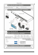
Connecting the PL-50 Power Controller - Monitor 6 Connecting the PL-50 Power Controller - Monitor To connect the PL-50, as illustrated in the example in Figure 4, do the following 1: 1. Connect up to five 2 outlets (from 1 to 5). For example, connect: OUT 1 to a DVD player OUT 2 to an LCD display OUT 4 to a power amplifier with speakers OUT 5 to a lighting system 2. Set the DIP-switches (see Table 2). 3.
Connecting the PL-50 Power Controller - Monitor 6.1 Connecting the Relays Figure 5 shows how to connect the relay. To Alarm Figure 5: Relay Wiring On each 3-pole terminal block connector, connect either: C to NC, or C to NO. Table 3 defines the Relay PINOUT: Table 3: Relay PINOUT RELAY PINOUT C Common NO Normally Open (relay is open by default and closes for activation) NC Normally Closed (relay is closed by default and opens for activation) 6.
Connecting the PL-50 Power Controller - Monitor 5. Select the Internet Protocol (TCP/IP) and click the Properties button (see Figure 6). Figure 6: Local Area Connection Properties Window 6. Select Use the following IP address, and fill in the details as shown in Figure 7. 7. Click OK. Figure 7: Internet Protocol (TCP/IP) Properties Window 6.2.
Connecting the PL-50 Power Controller - Monitor 6.2.3 Configuring the Ethernet Port Initially To initially configure the Ethernet port, download the K-UPLOAD Ethernet configuration software 1. Extract the file to a folder and create a shortcut on your desktop to the file. Follow these steps to configure the port: 1. Double click the desktop icon the K-UPLOAD screen appears: Figure 8: K-UPLOAD Main Screen 2. Click the Connect button.
Connecting the PL-50 Power Controller - Monitor Figure 9: Connect Screen 3. Connect a USB cable from a USB port on the PC to the USB port on the PL-50 (you can also connect to the PC via the Ethernet or a serial connector). 4. Check USB as the connection method and select the com port from the USB drop down list. 5. Click Connect. The K-UPLOAD screen appears. Figure 10: Device Properties Screen 6. If required, make changes and click Save. If not, click Exit.
Connecting the PL-50 Power Controller - Monitor 6.3 Controlling via the Embedded Web Pages The embedded Web page can be used to remotely operate the PL-50 via the Ethernet (see section 6.2). 6.3.1 Setting the Embedded Web Page Before you use the embedded Web pages to control the PL-50 via the Ethernet, check that the Java™ software is installed on your computer. If not, download it from: www.java.com.
Connecting the PL-50 Power Controller - Monitor Check that Java and JavaScript is enabled in your browser. The following window appears: Figure 13: Running the Application 3. Click Run. The PL-50 front panel is displayed on your screen (see Figure 14). The Web embedded screens let you control the PL-50 via the Ethernet. The menu appears on the left side of the screen. The web embedded pages include a security system (see Section 6.3.8.1).
Connecting the PL-50 Power Controller - Monitor 6.3.2 The Panel Screen The Panel screen lets you select one or more channels in order to read the Standby or Active values and turn the power outlet ON/OFF: Figure 14: HOME Embedded Web Page The connection icon on the top right screen indicates whether the machine is connected to your PC or not . Click the on-screen channel buttons: 1 2 3 4 5 Figure 15: Selecting a Channel Each channel button includes red and green indicators.
Connecting the PL-50 Power Controller - Monitor 6.3.3 The Scheduler Screen The Scheduler screen lets you schedule the operation of the outlets on a weekly basis.
Connecting the PL-50 Power Controller - Monitor After scheduling the outlets, the Scheduler screen appears as follows: Figure 17: Scheduling the Outlets In Figure 17, the channels are scheduled at different times. For example: • On Monday, Channel 2 will be ON from 12:00 to 13:00 and Channel 5 will be ON from 12:00 to 14:00 • On Tuesday, Channel 2 will be ON from 08:00 to 09:31, from 12:00 to 14:00 and from 15:00 to 18:00.
Connecting the PL-50 Power Controller - Monitor 6.3.
Connecting the PL-50 Power Controller - Monitor 6.3.
Connecting the PL-50 Power Controller - Monitor After setting the alarms, the Alerts screen appears as follows: Figure 20: Setting the Alarms In this example, Channel 2 and Channel 3 are enabled, and the events (TO ACTIVE and TO ON, respectively) trigger the ALARM The duration of the alarm is 60 seconds and it will activate both the relay alarm and the digital control alarm. Click Test Alarm to test the alarm. HELP BOX This page lets you view and set all the Alerts the device will trigger.
Connecting the PL-50 Power Controller - Monitor 6.3.
Connecting the PL-50 Power Controller - Monitor 6.3.7 The Power ON/OFF Order Screen The Power ON/OFF Order screen lets you determine the power ON and OFF order for channels that are scheduled to switch ON/OFF simultaneously. This is very convenient for systems that require a specific power up or shut down sequence.
Connecting the PL-50 Power Controller - Monitor In the example illustrated in Figure 23, the Power OFF Order is set from 5 to 1 with a 10 second delay time before each channel in the sequence is switched OFF: Figure 23: Power ON Order Example The system switches ON according to the Power ON Order, with a 1 second delay before powering ON each channel: Power ON Channel 5 1sec Delay Power ON Channel 3 1sec Delay Power ON Channel 1 1sec Delay Power ON Channel 2 1sec Delay Power ON Channel 4 Figure
Connecting the PL-50 Power Controller - Monitor 6.3.8 The Configurations Screen The Configurations page lets you view and change some Ethernet settings 1 (see Figure 25) and also set the security level. To change Configuration definitions: 1. Click Configurations. The Configurations Web page appears. 2. Change the definitions as required. 3. Click the Submit button to apply changes2. A window appears asking if you are sure you want to change the network settings. 4. Click Yes.
Connecting the PL-50 Power Controller - Monitor If the security system is disabled, the embedded Web pages can be accessed, and the parameters changed by anyone. Check the Security box to enable the security system.
Connecting the PL-50 Power Controller - Monitor 6.3.8.1 The Security System Set the user password and Admin password 1 (by default, the passwords for both User and Admin are empty fields).
Operating Your PL-50 Power Controller – Monitor 6.
Operating Your PL-50 Power Controller – Monitor To set the Standby mode 1, do the following: 1. Press one or more OUT buttons to select the channels for which you want to measure the standby or active modes. The selected buttons illuminate. 2. Set the connected units to the Standby mode 3. Press the PRESET LEVEL STANDBY button. The selected orange OUT buttons, and their related STANDBY orange LEDs blink. 4. Press each of the selected orange blinking buttons to initialize the measurement.
Flash Memory Upgrade 8 Flash Memory Upgrade The PL-50 uses a microcontroller that runs firmware located in FLASH memory. The latest version of firmware can be downloaded from the Kramer Web site at www.kramerelectronics.com and updated in minutes using the K-UPLOAD and the following procedures. Before firmware upgrade: Close the embedded Web pages Do not press the front panel buttons 8.1 Upgrading the Firmware To upgrade the PL-50 firmware: 1. Download the firmware file from the Internet (see section 8.
Flash Memory Upgrade 8.1.3 Update the Firmware To update the firmware, perform the following steps: 1. Open the K-UPLOAD software 1 by double-clicking the desktop icon K-UPLOAD. The K-UPLOAD screen appears 2: Figure 30: K-UPLOAD Screen 2. Click the Connect button. The Connect Window appears (see Figure 31). Figure 31: Connect Ethernet by IP Number 1 You can download and install the latest version of K-UPLOAD from http://www.kramerelectronics.com.
Flash Memory Upgrade 3. If you are upgrading using an Ethernet connection, check Ethernet. To reset the device address to the factory default address, click Default and the address 192.168.1.39 appears. If you are upgrading using: RS-232 check Serial, and select the COM port to connect USB, check USB and select the USB device to connect 4. Click Connect.
Flash Memory Upgrade Figure 33: K-UPLOAD Connected Note: In the Device Properties section, you can update any of the active fields that have a white background. After making any changes, click Save. 5. Click the Browse button, select the file from the Open window and then click Open.
Flash Memory Upgrade 6. Click the UPLOAD button to begin the file transfer. The Warning window appears: Figure 35: Warning Window 7. Click OK to continue.
Flash Memory Upgrade 8. When the update is finished, the restart message appears: Figure 37: Restart Message 9. Click Restart now to close K-UPLOAD and remove the cable that connects the PL-50 to the PC.
Technical Specifications 8.2 Changing the Device Parameters To change the device parameters do the following: 1. Connect a PC to the PL-50 (see section 8.1.2). 2. Open K-UPLOAD (see Figure 30). 3. Click the Connect button to open the Connect window (see Figure 31). 4. Choose the appropriate type of connection: Ethernet, Serial or USB, and click Connect. The Connect window disappears and the Device Properties become visible. 5. Change the parameters as required and then click Save.
Kramer Protocol 3000 10 Kramer Protocol 3000 The Ethernet/USB/RS-232/RS-485 1 communication protocol 2 lets you control the machine from any standard terminal software (for example, Windows® HyperTerminal Application). 10.
Kramer Protocol 3000 10.2 Command Terms Command: Sequence of ASCII letters ('A'-'Z', 'a'-'z' and '-'). Command will separate from parameters with at least single space. Parameters: Sequence of Alfa-Numeric ASCII chars ('0'-'9','A'-'Z','a'-'z' and some special characters for specific commands), parameters are separated by commas. Message string: Every command entered as part of a message string begins with a message starting character and ends with a message closing character.
Kramer Protocol 3000 10.
Kramer Protocol 3000 FACTORY Cmd Short Description Command Type Reset to factory default config Common Usage: Syntax Permission Administrator Response NAME Cmd Short Description Command Type Set machine (DNS) name Common Permission Administrator Usage: Syntax Response NAME MACHINE_NAME NAME MACHINE_NAME RESULT NAME? Cmd Short Description Command Type Get machine (DNS) name Common Usage: Syntax Response NAME? NAME MACHINE_NAME Permission End User *Note: The machine name is not
Kramer Protocol 3000 UPGRADE Cmd Short Description Command Type Execute firmware upgrade Common Permission Administrator Usage: Syntax Response UPGRADE UPGRADE OK Firmware usually uploads to a device via a command like LDFW. The device may need to be reset to complete the process. 10.4 Result and Error Codes Syntax Command ran successfully, no error.
Kramer Protocol 3000 PASS Cmd Short Description Set password Command Type Security Permission Administrator Usage: Syntax Response PASS ID , PASS PASS ID , PASS RESULT PASS? Cmd Short Description Query password Command Type Security Permission Administrator Usage: Syntax Response PASS? ID PASS ID , PASS RESULT SECUR Cmd Short Description Start/Stop Security Usage: Syntax Command Type Security Permission Administrator Response SECUR ON/OFF ON/OFF = 0 or OFF, 1 or ON SECUR ON/OF
Kramer Protocol 3000 NET-DHCP Cmd Short NTDH Description Set DHCP mode Command Type Ethernet Permission Administrator Usage: Syntax Response NET-DHCP DHCP_MODE NET-DHCP DHCP_MODE RESULT DHCP_MODE = ‘0’ – Don't use DHCP (Use IP set by factory or IP set command). ‘1’ – Try to use DHCP, if unavailable use IP as above.
Kramer Protocol 3000 NET-MAC? Cmd Short NTMC? Description Read MAC address Command Type Ethernet Permission End User Usage: Syntax Response NET-MAC? NET-MAC MAC_ADDRESS NET-MASK Cmd Short NTMSK Description Set subnet mask Usage: Syntax Command Type Ethernet Permission Administrator Response NET-MASK SUBNET_MASK Ex: 255.255.000.
Kramer Protocol 3000 ALARM-OFF Cmd Short Description Set alarm OFF Command Type PL-50 Usage: Syntax Response ALARM-OFF ALARM-OFF RESULT Permission User ALARM-ON Cmd Short Description Set alarm ON Command Type PL-50 Usage: Syntax Response ALARM-ON ALARM-ON RESULT Permission User ALARM-ON? Cmd Short Description Query alarm status Command Type PL-50 Usage: Syntax Response ALARM-ON? ALARM-ON 1/0 Permission User 1/0= On OR Off ALARM-START-AS Cmd Short Description Set alarm Relay
Kramer Protocol 3000 ALERT-REG? Cmd Short Description Query Alert Registration Command Type PL-50 Permission User Usage: Syntax Response ALERT-REG? CHNL ALERT-REG? CHNL ,EVENT ,ACTION CHNL = (1-5) EVENT = (TO_OFF,TO_ON,TO_FULL,TO_STBY,TO_NONE,ANY_CHANGE) ACTION = (NO_ALERT,ALARM, ALL_ALERTS) MEASURE Cmd Short Description Device notification Usage: Syntax Command Type Permission PL-50 Response MEASURE CHNL ,MES-MODE Query the "full" and "standby" LED status.
Kramer Protocol 3000 SWITCH? Cmd Short Description Command Type Query channel switch PL-50 Permission User Usage: Syntax Response SWITCH? CHNL SWITCH? CHNL ,STATUS CHNL = (1-5) STATUS = (0=OFF,1=ON,2=ON-SCHEDULER,3=OFF-SCHEDULER ,4=ACTIVE-MEASURE,5=STANDBYMEASURE) SWITCH-ORDER Cmd Short Description Set the switch order Usage: Syntax Permission Administrator Response SWITCH-ORDER ON/OFF, C, C, C, C, C CHNL = C = (1-5) Command Type PL-50 SWITCH-ORDER ON/OFF, C, C, C, C, C RESULT ON/OFF =
LIMITED WARRANTY Kramer Electronics (hereafter Kramer) warrants this product free from defects in material and workmanship under the following terms. HOW LONG IS THE WARRANTY Labor and parts are warranted for seven years from the date of the first customer purchase. WHO IS PROTECTED? Only the first purchase customer may enforce this warranty. WHAT IS COVERED AND WHAT IS NOT COVERED Except as below, this warranty covers all defects in material or workmanship in this product.
For the latest information on our products and a list of Kramer distributors, visit our Web site: www.kramerelectronics.com, where updates to this user manual may be found. We welcome your questions, comments and feedback. Safety Warning: Disconnect the unit from the power supply before opening/servicing. Caution Kramer Electronics, Ltd. Web site: www.kramerelectronics.com E-mail: info@kramerel.