Kramer Electronics, Ltd.
Contents Contents 1 2 3 4 5 5.1 5.2 5.3 6 6.1 6.2 6.3 6.4 6.5 6.6 7 7.1 7.2 7.3 7.
Contents Tables Table 1: RC-8IR Front Panel Features Table 2: RC-8IR Right Side Panel Features Table 3: RC-8IR and Rear Panel Features Table 4: Connection Scheme (for the example in Figure 8) Table 5: The Commands Configuration Table 6: Technical Specifications of the RC-8IR Universal Room Controller ii 3 4 5 9 10 15 KRAMER: SIMPLE CREATIVE TECHNOLOGY
Introduction 1 Introduction Welcome to Kramer Electronics! Since 1981, Kramer Electronics has been providing a world of unique, creative, and affordable solutions to the vast range of problems that confront the video, audio, presentation, and broadcasting professional on a daily basis. In recent years, we have redesigned and upgraded most of our line, making the best even better! Our 1,000-plus different models now appear in 11 groups 1 that are clearly defined by function.
Overview 3 Overview Kramer’s RC-8IR one-gang wall plate is a highly versatile controller interface that acts as an all-in-one extended remote control panel for control of A/V equipment—especially projectors and associated equipment—in any room (such as classrooms, boardrooms, or auditoriums). It streamlines operations and simplifies control by integrating audio, video, and computervideo sources into a centralized system.
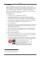
Your Universal Room Controller 4 Your Universal Room Controller Figure 1 and Table 2 define the RC-8IR front panel: Front Panel with Faceplate Front Panel without Faceplate Figure 1: RC-8IR Front Panel Table 1: RC-8IR Front Panel Features 1 2 3 4 5 # Feature Faceplate Attachment Holes IR IN Receiver Configurable Control Buttons (Macro Buttons) Housing Attachment Holes Button Caps Function Use to attach the faceplate to the device housing (see Table 2) Accepts IR remote commands (for the IR-learner f
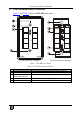
Your Universal Room Controller Figure 2 and Table 2 define the RC-8IR right side panel: Front Panel Buttons Figure 2: RC-8IR Right Side Panel Table 2: RC-8IR Right Side Panel Features 1 2 3 4 5 6 7 8 # Feature Housing and Faceplate Support RELAY2 RELAY1 RS-485 Terminal Block Connector RS-232 Terminal Block Connector (1 and 2) IR OUT1 PIN GND PIN IR OUT2 PIN GND PIN +12VDC IN PIN Function Device housing supports the faceplate Connect each relay to a room item (such as lighting, screen settings, blinds
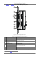
Installing the RC-8IR Universal Room Controller Figure 3 and Table 3 define the RC-8IR rear panel: Figure 3: RC-8IR Rear Panel Table 3: RC-8IR and Rear Panel Features 1 2 3 4 5 6 5 # Feature N.U Switch PROGRAM Switch Function Not used Switch to OFF for normal operation; Switch to ON for firmware upgrade RS-485 TERM.
Installing the RC-8IR Universal Room Controller 5.1 Setting the Labels and Button Caps To install the labels and button caps: 1. Remove the required labels from the supplied button label sheet. 2. Hold the button cap so that it is oriented as shown in Figure 4 with the “wings” on the left and right sides, and insert the label inside the cap. Figure 4: Button Cap Orientation 3. Repeat for all eight caps. 4. Retaining the orientation, place the eight button caps on the buttons of the RC-8IR (see Figure 5).
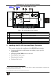
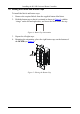
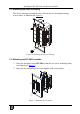
Installing the RC-8IR Universal Room Controller 5.2 Mounting the Device Housing The device housing is mounted to the wall via the two housing mounting screws holes, as illustrated in Figure 6: Figure 6: Mounting the Device Housing 5.3 Mounting the RC-8IR Faceplate 1. Place the faceplate on the RC-8IR so that the two screw mounting holes are aligned (see Figure 7). 2. Insert the two mounting screws and tighten with a screwdriver.
Using the RC-8IR Universal Room Controller 6 Using the RC-8IR Universal Room Controller Connecting the inputs and the display Configuration via the Windows®based configuration software and/or the IR learner 1 is described in the RC Configuration guide. The cable installation process is not detailed in this user manual 2.
Using the RC-8IR Universal Room Controller Table 4: Connection Scheme (for the example in Figure 8) This connector: RELAY2 RELAY1 RS-485 Terminal Block Connector RS-232 (TX1, RX1) Terminal Block Connector IR OUT1 PIN 2 IR OUT2 PIN2 Ethernet A laptop is connected to the projector Controls: The lights The screen A power amplifier (and speakers) 1 A projector A DVD player A video player The RC-8IR via a remote control PC Figure 9 shows the RC-8IR built into a podium that is located in a lecture auditorium.
Using the RC-8IR Universal Room Controller 6.1 Operating the RC-8IR In the following example 1 that is illustrated in Figure 10, the RC-8IR is labeled with specific functions and each button is programmed 2 to perform several tasks 3 as defined in Table 5. Each button may be assigned with up to 15 commands.
Using the RC-8IR Universal Room Controller 6.
Using the RC-8IR Universal Room Controller 6.3 Using the Macro Buttons Pressing any button initiates a macro sequence 1, during which the button blinks (as programmed by the system integrator). If during the macro sequence the button blinks faster than usual 2, this indicates that a malfunction has been detected 3 and the RC-8IR exits the macro sequence. To solve the problem, summon technical help 4 If you want to stop a macro sequence, press and hold that button for 5 seconds.
Flash Memory Upgrade 1. Type the unit’s IP number 1 in the Address bar of your browser (or type any link defined by the system integrator). The RC-8IR front panel is displayed on your screen (see Figure 12). 2. Press the on-screen buttons to control the unit.
Flash Memory Upgrade 7.2 Connecting the PC to the RS-232 Port Before installing the latest Kramer Ethernet firmware version on the RC-8IR, do the following: 1. Connect the RS-232 port (COM 1) on the RC-8IR to a Null-modem adapter and connect the Null-modem adapter with a 9-wire flat cable to the RS-232 9-pin D-sub COM port on your PC. 2. Set the PROGRAM switch to ON. 3. Connect the power on your machine. 7.3 Upgrading Firmware Follow these steps to upgrade the firmware: 1.
Technical Specifications 7.4 Installing the Web Applet Follow these steps to install the Web Applet 1: 1. Connect RC-8IR to your PC through computer networking. 2. Start the RC Configuration Software and connect to the RC device (see the RC Configuration and Installation Guide2). 3. In the Device menu select Upgrade Applet option and browse to MC.dat file included in the package. 4. Wait until uploading is completed and the success message appears. Click OK.
LIMITED WARRANTY Kramer Electronics (hereafter Kramer) warrants this product free from defects in material and workmanship under the following terms. HOW LONG IS THE WARRANTY Labor and parts are warranted for seven years from the date of the first customer purchase. WHO IS PROTECTED? Only the first purchase customer may enforce this warranty. WHAT IS COVERED AND WHAT IS NOT COVERED Except as below, this warranty covers all defects in material or workmanship in this product.
For the latest information on our products and a list of Kramer distributors, visit our Web site: www.kramerelectronics.com, where updates to this user manual may be found. We welcome your questions, comments and feedback. Safety Warning: Disconnect the unit from the power supply before opening/servicing. Caution P/N: 2900- 000695 Rev: 1 Kramer Electronics, Ltd. Web site: www.kramerelectronics.com E-mail: info@kramerel.