Kramer Electronics, Ltd.
Contents Contents 1 2 2.1 3 4 5 6 6.1 7 7.1 Introduction Getting Started Quick Start Overview Your Picture in Picture Inserter Machines Installing on a Rack Connecting the PIP-300 Picture in Picture Inserter Connecting a PC Configuring and Operating your PIP-300 Using the Menu 1 1 1 3 4 8 9 11 12 12 7.1.1 7.1.2 7.1.3 7.1.4 The Mode Submenu The Video Settings Submenu The Presets Submenu The Labeling Submenu 14 15 15 16 7.2 Displaying the Layers in the PIP Mode 17 7.2.
Contents Tables Table 1: Front Panel Picture in Picture Inserter Features Table 2: Rear Panel Picture in Picture Inserter Features Table 3: The PIP-300 Main Menu Items Table 4: The MODE Submenu Features Table 5: PIP Sizing and Positioning Features Table 6: Recommended PIP sizes Table 7: Video Settings Submenu Features Table 8: Presets Submenu Features Table 9: Technical Specifications of the PIP-200xl and PIP-300 Picture in Picture Inserter Table 10: Protocol Definitions Table 11: Instruction Codes for the
Introduction 1 Introduction Welcome to Kramer Electronics (since 1981): a world of unique, creative and affordable solutions to the infinite range of problems that confront the video, audio and presentation professional on a daily basis. In recent years, we have redesigned and upgraded most of our line, making the best even better! Our 500-plus different models now appear in 8 Groups1, which are clearly defined by function.
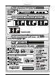
Getting Started MENU Items MODE: OSD: BORDER: VIDEO SETTINGS: ENTER ESC INPUT SELECT: OUTPUT STANDARD: PRESETS: LABELING: 2 KRAMER: SIMPLE CREATIVE TECHNOLOGY
Overview 3 Overview The high performance PIP-200xl/PIP-300 is a picture-in-picture inserter for composite video, s-Video (Y/C) and component video (YUV1).
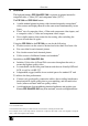
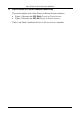
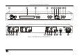
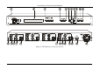
Your Picture in Picture Inserter Machines 4 Your Picture in Picture Inserter Machines This section defines each of the Picture-in-Picture Inserter machines: Figure 1 illustrates the PIP-200xl Picture in Picture Inserter Figure 2 illustrates the PIP-300 Picture in Picture Inserter Table 1 and Table 2 define the Picture in Picture Inserter machines.
Your Picture in Picture Inserter Machines Figure 1: PIP-200xl Picture in Picture Inserter 5
Your Picture in Picture Inserter Machines Figure 2: PIP-300 Picture in Picture Inserter 6 KRAMER: SIMPLE CREATIVE TECHNOLOGY
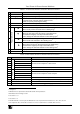
Your Picture in Picture Inserter Machines Table 1: Front Panel Picture in Picture Inserter Features # 1 2 3 Feature POWER Switch LCD Display 2 INPUTS Buttons 4 5 6 LAYER Button 3 FREEZE Button 8 9 Moves the selected image upwards in the PIP mode4 Moves up one step (in the same level) in the OSD screen Increases the range by one step in the OSD screen Use to change the selected character in the Labeling menu5 Navigation Buttons 7 Function Illuminated switch for turning the unit ON or OFF 1 Displays d
Installing on a Rack 5 Installing on a Rack This section describes what to do before installing on a rack and how to rack mount. Before Installing on a Rack Before installing on a rack, be sure that the environment is within the recommended range: How to Rack Mount To rack-mount a machine: 1 Attach both ear brackets to the machine. To do so, remove the screws from each side of the machine (3 on each side), and replace those screws through the ear brackets.
Connecting the PIP-300 Picture in Picture Inserter 6 Connecting the PIP-300 Picture in Picture Inserter To connect your PIP-3001, as the example in Figure 3 illustrates, do the following2: 1. On the INPUT 1 set3 connect4: An s-Video source to the Y/C INPUT 4p connector (for example, an s-Video player 1) A component video source to the Y, B-Y, and R-Y INPUT BNC connectors (for example, a BETACAM video player 1) 2.
Connecting the PIP-300 Picture in Picture Inserter Betacam Video Player 1 Component Video Projector s-Video Player 1 RS-232 Composite Video Player 2 Composite Video Player 3 Composite Video Display s-Video Display Figure 3: Connecting the PIP-300 Picture in Picture Inserter 10 KRAMER: SIMPLE CREATIVE TECHNOLOGY
Connecting the PIP-300 Picture in Picture Inserter 6.
Configuring and Operating your PIP-300 7 Configuring and Operating your PIP-300 You can configure and operate your PIP-300 via: The front panel buttons, and/or RS-232 serial commands transmitted by a touch screen system, PC, or other serial controller 7.1 Using the Menu Use the front panel buttons to activate the menu. The menu is displayed1 on the LCD display2 and is also superimposed on the screen2, 3.
Configuring and Operating your PIP-300 1/1 1/4 SINGLE PIP SIZING MODE 1/9 1/16 OFF PIP ON OSD PIP POSITION OFF USE ARROWS TO MOVE ON BORDER ENTER VIDEO SETTINGS OFF WHITE COLOUR BLACK CONTRAST USE UP/DOWN KEYS SATURATION USE UP/DOWN KEYS BRIGHTNESS USE UP/DOWN KEYS COMPOSITE INPUT SELECT S-VIDEO COMPONENT NTSC OUTPUT STANDARD PAL STORE PRESETS RECALL EDIT LABEL LABELING LABEL ON STORE PRESET 1 STORE PRESET 2 RECALL PRESET 1 RECALL PRESET 2 FACTORY DEFAULT LABEL OFF Figure 5: The
Configuring and Operating your PIP-300 7.1.1 The Mode Submenu Table 4 defines the MODE submenu features: Table 4: The MODE Submenu Features Mode SINGLE PIP Function Displays one input channel at a time on the screen (full screen display). The LCD display shows the display mode and the selected channel, for example, “Single Mode – Channel 2” 1 Displays all 3 input channels on the screen.
Configuring and Operating your PIP-300 When using one of the inputs as a full-sized background (PIP size 1/1), it is recommended to limit the sizes of the other PIP windows according to Table 6. Combinations having window sizes larger than recommended, may result in intermittent interruptions in the picture. Note that these restrictions only apply when a 1:1 sized picture is used.
Configuring and Operating your PIP-300 7.1.4 The Labeling Submenu The labeling submenu lets you display labels over the input pictures, remove them from the display or edit them. To turn labels on or off select the LABEL ON or LABEL OFF items in the LABELING menu respectively. The input pictures are labeled1 Channel 1 to Channel 3 by default2. You can edit the text labels for each channel by using the labeling submenu: Press ENTER on the LABELING submenu and choose the EDIT LABEL command.
Configuring and Operating your PIP-300 7.2 Displaying the Layers in the PIP Mode To display a picture in picture on the screen, do the following: 7.2.1 1. Select an input. 2. Select the PIP mode. 3. Size and position each layer as desired1. 4. Press an INPUT button to bring forward that input on the screen. Selecting a Different Channel as the Background In the following example, Channel 2 replaces Channel 3 as the background.
Firmware Upgrade 8 Firmware Upgrade The PIP-300 firmware is located in FLASH memory, which lets you upgrade to the latest Kramer firmware version in minutes! The process involves: Downloading from the Internet (see section 8.1) Connecting the PC to the RS-232 port (see section 8.2) Upgrading firmware (see section 8.3) 8.1 Downloading from the Internet You can download the up-to-date file from the Internet. To do so: 1. Go to our Web site at http://www.kramerelectronics.
Firmware Upgrade Figure 7: Goal Screen 2. Click the Open… button to select the new firmware hex file1. 3. Click the Options… button, select the Inverted2 check box in the Reset Polarity area and Click OK. 4. In the Action area, select Erase then Program. 5. Click the START button. The software erases and then programs flash memory. Upon Completion of the operation, the System Status Window displays: “Erase and program completed successfully” (see Figure 8). Figure 8: System Status Screen 6.
Technical Specifications 9 Technical Specifications Table 9 includes the technical specifications1: 2 Table 9: Technical Specifications of the PIP-200xl and PIP-300 Picture in Picture Inserter INPUTS: OUTPUTS: PIP-200xl 2 sets, each with: 1 composite video 1Vpp/75 on a BNC connector 1 s-Video 1Vpp, 0.3Vpp/75 on a 4p connector 1 component video 1Vpp, 0.7Vpp, 0.7Vpp/75 on BNC connectors PIP-300 3 sets, each with: 1 composite video 1Vpp/75 on a BNC connector 1 s-Video 1Vpp, 0.
Communication Protocol 10 Communication Protocol1 This RS-232/RS-485 communication protocol uses four bytes of information as defined below. A null-modem connection (pin 2 and pin 3 crossed; pins 5 connected together) is used to link the PIP unit to the controller unit (for example, PC). The data rate is 9600 baud, with no parity, 8 data bits and 1 stop bit. When switching (for example, instruction codes 1 and 2), the INPUT (7 bits) is set as the input number, which is to be switched.
Communication Protocol Table 11: Instruction Codes for the Communication Protocol INSTRUCTION # (Hex) Description DEFINITION FOR SPECIFIC INSTRUCTION BYTE2 BYTE3 0x00 0x01 0x02 Reset 0 Active input select 1 to 5 – select input number Mode select 0 0x03 Store 0x04 0x09 Recall 0 to 0x02 – address to retrieve Video input format 1 to 5 – input number 0x0A Request video input standard 1 to 5 – input number 0x0B Video output standard 0 0x10 0x11 0x12 0x13 0x1a Error Contrast Saturation Brightness P
Communication Protocol DETAILS OF INSTRUCTION SET Instruction 0x00: Reset When machine is turned on, it sends a Reset code to the PC (0x40 0x80 0x80 0x88). If this code is sent to the switchers with Byte3 = 0, it will reset according to the present power-down settings. (See instruction #4 for resetting the PIP to its factory default state). Instruction 0x01: Input select Sending this instruction will select the input number that is specified in Byte2.
Communication Protocol Instruction 0x11: Contrast Send this instruction to set the CONTRAST (Byte3) of an input (Byte2). To request the CONTRAST value of an input, set the RQ bit. The unit responds by setting Byte3 appropriately. For example: To set the CONTRAST of input 2 to 0x7b, send 0x11 0x82 0xfb 0x88. To set the CONTRAST of input 2 to 0xac, send 0x11 0x82 0xac 0xc8 (MSB of BYTE3 is in LAST byte). To find out the CONTRAST setting of input 2, send 0x11 0xc2 0x80 0x88.
Communication Protocol Instruction 0x21 to Instruction 0x29: Labeling For these instructions, set Byte2 with the input number and set Byte3 is set with the hexadecimal value of the ASCII character. The character number is defined from right to left (when read), with the right-hand most character = character 1. Up to 9 characters are allowed in any label. To request the character of a label, define Byte2 as above, and set the RQ bit. The unit responds by setting Byte3 appropriately.
LIMITED WARRANTY Kramer Electronics (hereafter Kramer) warrants this product free from defects in material and workmanship under the following terms. HOW LONG IS THE WARRANTY Labor and parts are warranted for seven years from the date of the first customer purchase. WHO IS PROTECTED? Only the first purchase customer may enforce this warranty. WHAT IS COVERED AND WHAT IS NOT COVERED Except as below, this warranty covers all defects in material or workmanship in this product.
For the latest information on our products and a list of Kramer distributors, visit our Web site: www.kramerelectronics.com, where updates to this user manual may be found. We welcome your questions, comments and feedback. Safety Warning: Disconnect the unit from the power supply before opening/servicing. Caution Kramer Electronics, Ltd. Web site: www.kramerelectronics.com E-mail: info@kramerel.