Kramer Electronics, Ltd.
Contents Contents 1 2 2.1 3 3.1 3.2 3.3 4 4.1 4.2 4.3 5 5.1 5.2 5.3 5.
Introduction 1 Introduction Welcome to Kramer Electronics! Since 1981, Kramer Electronics has been providing a world of unique, creative, and affordable solutions to the vast range of problems that confront the video, audio, presentation, and broadcasting professional on a daily basis. In recent years, we have redesigned and upgraded most of our line, making the best even better! Our 1,000-plus different models now appear in 11 groups 1 that are clearly defined by function.
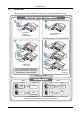
Getting Started 2.1 Quick Start This quick start chart summarizes the basic setup and operation steps.
Overview 3 Overview The TP-45/TP-45RC and TP-46 are a twisted pair transmitter and receiver for component video (YUV) or computer graphics video and unbalanced stereo audio or S/PDIF audio signals. The TP-45/TP-45RC transmitter converts audio and video to a twisted pair signal and the TP-46 converts the twisted pair signal back into audio and video signals.
Overview • Digital audio input (S/PDIF) on an RCA connector and a stereo analog input on a 3.5mm mini jack • The Power Connect feature where one unit can power the other over the same twisted pair cable (see section 3.
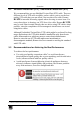
Overview 3.2 Shielded Twisted Pair (STP) / Unshielded Twisted Pair (UTP) We recommend that you use Shielded Twisted Pair (STP) cable. There are different levels of STP cable available, and we advise you to use the best quality STP cable that you can afford. Our non-skew-free cable, Kramer BC-STP is intended for analog signals where skewing is not an issue. For cases where there is skewing, our UTP skew-free cable, Kramer BC-XTP, may be used.
Your Component/XGA – Audio Transmitter and Receiver 4 Your Component/XGA – Audio Transmitter and Receiver This section describes the: • TP-45 Component/XGA – Audio Transmitter, see section 4.1 • TP-45RC Component/UXGA – Audio Transmitter, see section 4.2 • TP-46 Component/XGA – Audio Receiver, see section 4.3 4.
Your Component/XGA – Audio Transmitter and Receiver Figure 2 and Table 2 define the underside of the TP-45: Figure 2: TP-45 Component/XGA – Audio Transmitter (Underside) Table 2: TP-45 Component/XGA – Audio Transmitter (Underside) Features # 12 Feature VS Switch 13 HS Switch 4.2 Function Slide the switch up 1 (to NEG.) to change the VS polarity to negative polarity; slide the switch down (to NORM) to retain the polarity Slide the switch up1 (to NEG.
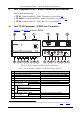
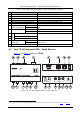
Your Component/XGA – Audio Transmitter and Receiver Table 3: TP-45RC Component/XGA – Audio Transmitter Features 7 8 9 Feature XGA IN 15-pin HD (F) Connector LINE OUT RJ-45 Connector CONTROL AUDIO/VIDEO Terminal Block 12V DC ANALOG AUDIO 3.
Your Component/XGA – Audio Transmitter and Receiver Table 4: TP-46 Component/XGA – Audio Receiver Features # 1 OUTPUTS 2 3 4 5 Feature XGA OUT 15-pin HD (F) Connector LINE IN RJ-45 Connector LINE OUT RJ-45 Connector 12V DC ANALOG AUDIO 3.
Connecting a Component/XGA – Audio Distribution System 5 Connecting a Component/XGA – Audio Distribution System The Component/XGA – Audio Distribution System can be configured to operate in one of two video modes: • In the XGA mode, a computer graphics source is connected to the input and transmitted to a display connected to the receiver (see section 5.1) • In the component video mode, a component video source is connected to the input and transmitted to a TV set connected to the receiver (see section 5.
Connecting a Component/XGA – Audio Distribution System 5.1 Connecting the System in XGA Mode To configure a TP-45/TP-45RC and TP-46 Component/XGA – Audio distribution system 1 in the XGA mode, as illustrated in the example in Figure 6, do the following: 1. On the TP-45 or TP-45RC, connect the following: • An XGA source (for example, the graphics card on a laptop) to the XGA 15-pin HD (F) connector • An analog audio source to the ANALOG AUDIO 3.
Connecting a Component/XGA – Audio Distribution System 7. Connect the 12V DC power adapter to the power socket and connect the adapter to the mains electricity on both1 the TP-45 and the TP-46 (not shown in Figure 6). The signal from the XGA source is transmitted via twisted pair cable, decoded and converted at the XGA OUT 15-pin HD (F) connector to the XGA acceptor. 8. If required, connect the LINE OUT RJ-45 connector on the TP-46 to an additional TP-46. 9.
Connecting a Component/XGA – Audio Distribution System 5.2 Connecting the System in Component Video Mode To configure a TP-45/ TP-45RC/TP-46 Component/XGA – Audio distribution system 1 in the component video mode, as the example in Figure 7 illustrates, do the following: 1. On the TP-45 or TP-45RC, connect the following: • A component video source (for example, a DVD player) to the Y, Cb/Pb, Cr/Pr RCA connectors • A digital audio source to the S/PDIF RCA connector 2 2.
Connecting a Component/XGA – Audio Distribution System TP-46 (not shown in Figure 7). The signal from the component video source is transmitted via the twisted pair cable; decoded and converted to component video and outputted on the Y, CB/PB, CR/PR OUTPUTS RCA connectors to the component video acceptor. 8. Connect the LINE OUT RJ-45 connector on the TP-46 to a second TP-46 unit1 (optional). 9. Similarly, you can connect the LINE OUT RJ-45 connector on the TP-46 to additional TP-46 units. 10.
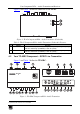
Connecting a Component/XGA – Audio Distribution System 6 -4 P T TP-46 r e iv e c e R Audio A G X t/ n e n o p m o C - io d u A YUV XG AO UT LIN Plasma Display EI N LIN EO UT To the next TP-46 unit CA T5 6 -4 P T TP-46 r e iv e c e R Audio A G X t/ n e n o p m o C - io d u A YUV XG AO UT LIN Plasma Display EI N ble LIN EO UT ble ng T5 CA ng T5 CA ca Lo ca Lo TP-45RC XG A IN LIN EO UT Audio YUV DVD Player Figure 7: Component/XGA – Audio Distribution System, C
Connecting a Component/XGA – Audio Distribution System 5.3 Connecting the TP-45RC Remote Control Connect momentary push-buttons and LEDs 1 to a cable and attach the cable to a 5-pin terminal block for connection to the TP-45RC control port as shown in Figure 8. Each press of the selector button toggles the audio or video system mode and turns on or off the remote and panel status LEDs according to the active mode.
Connecting a Component/XGA – Audio Distribution System 5.
Technical Specifications 6 Technical Specifications Table 7 defines the technical specifications 1: Table 7: Technical Specifications 2 of the TP-45/TP-45RC/TP-46 VIDEO Specifications INPUTS: TP-45/RC 1 VGA/UXGA 1Vpp/75Ω on a 15-pin HD connector 1 component 1Vpp/75Ω (YPbPr) on 3 RCA connectors TP-46 OUTPUTS: TP-46 MAX. INPUT LEVEL: RETURN LOSS: MAX.
LIMITED WARRANTY Kramer Electronics (hereafter Kramer) warrants this product free from defects in material and workmanship under the following terms. HOW LONG IS THE WARRANTY Labor and parts are warranted for seven years from the date of the first customer purchase. WHO IS PROTECTED? Only the first purchase customer may enforce this warranty. WHAT IS COVERED AND WHAT IS NOT COVERED Except as below, this warranty covers all defects in material or workmanship in this product.
For the latest information on our products and a list of Kramer distributors, visit our Web site: www.kramerelectronics.com, where updates to this user manual may be found. We welcome your questions, comments and feedback. Safety Warning: Disconnect the unit from the power supply before opening/servicing. Caution PN: 2900- 000424 Rev: 3 Kramer Electronics, Ltd. Web site: www.kramerelectronics.com E-mail: info@kramerel.