Kramer Electronics, Ltd.
Contents Contents 1 2 2.1 3 3.1 3.2 4 4.1 4.2 5 5.
Introduction 1 Introduction Welcome to Kramer Electronics! Since 1981, Kramer Electronics has been providing a world of unique, creative, and affordable solutions to the vast range of problems that confront the video, audio, presentation, and broadcasting professional on a daily basis. In recent years, we have redesigned and upgraded most of our line, making the best even better! Our 1,000-plus different models now appear in 11 groups 1 that are clearly defined by function.
Getting Started 2.
Overview 3 Overview Using the TP-9 Audio/Video Line Transmitter with the TP-10 Audio/Video Line Receiver constitutes an Audio/Video Line transmitter/receiver system. The TP-9 accepts the audio and video input signals, encodes and sends them to the CAT 5 cable. The TP-10 receives the CAT 5 signal, which includes both audio and video, decodes and distributes it to the audio and video acceptors.
Overview 3.1 About the Power Connect Feature The Power Connect feature applies as long as the cable can carry power. This feature is available when using STP cable and the distance does not exceed 50m on standard CAT 5 cable. For longer distances, heavy gauge cable should be used 1. For units which are connected via RJ-45 connectors, make sure that the shield of the STP cable is connected to the metal casing of the connectors on both ends of the cable.
Your Audio/Video Line Transmitter and Line Receiver 4 Your Audio/Video Line Transmitter and Line Receiver This section describes the: • TP-9 Audio/Video Line Transmitter, see section 4.1 • TP-10 Audio/Video Line Receiver, see section 4.2 4.
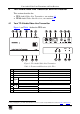
Your Audio/Video Line Transmitter and Line Receiver Figure 2 and Table 2 define the switches on the underside of the TP-9: Figure 2: TP-9 Audio/Video Line Transmitter Underside Table 2: TP-9 Audio/Video Line Transmitter Underside Features # 1 2 6 Feature VIDEO Input Selector CV Switch Y/C AUDIO Input Selector S/PDIF Switch ANALOG Function Set to CV to transmit composite video Set to Y/C to transmit s-Video Set to S/PDIF to transmit digital audio Set to ANALOG to transmit analog audio KRAMER: SIMPLE CR
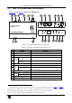
Your Audio/Video Line Transmitter and Line Receiver 4.2 Your TP-10 Audio/Video Line Receiver Figure 3 and Table 3 define the TP-10 unit: 5 6 7 4 3 2 8 1 13 1 2 7 8 3 9 4 5 6 10 11 12 13 Figure 3: TP-10 Audio/Video Line Receiver Table 3: Features and Functions of the TP-10 9 10 11 12 13 IR SENSOR EQ. Trimmer 2 CV/Y LEVEL Trimmer2 C LEVEL Trimmer2 ON LED 5 AUDIO OUT 6 7 8 Feature CV OUT BNC Connector Y/C OUT 4-pin Connector LINE IN RJ-45 Connector S/PDIF RCA Connector ANALOG 3.
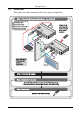
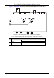
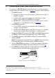
Connecting an Audio/Video Distribution System 5 Connecting an Audio/Video Distribution System To configure a TP-9/TP-10 audio/video distribution system (for example, for high quality home cinema system), as Figure 5 illustrates, do the following: 1. On the TP-9 connect: A composite video source (for example, a video player) to the CV IN BNC connector A digital audio source (for example, the video player’s audio signal) to the AUDIO IN S/PDIF RCA connector The IR OUT 2, 3.
Connecting an Audio/Video Distribution System Be sure to place the TP-10 in such a way that the IR SENSOR window will be in the line-of-sight of your IR remote controller. CV o e id V / o i d u A e in L r te it m s n a r T -9 P T You can now operate the video player via its IR remote controller from a distance.
Connecting an Audio/Video Distribution System 5.
Technical Specifications 6 Technical Specifications Table 5 defines the technical specifications 1: Table 5: Technical Specifications 2 of the TP-9/TP-10 TP-9 TP-10 INPUTS: 1 composite video 1Vpp/75Ω on a BNC connector 1 s-Video 1Vpp/75Ω [Y], 0.3Vpp/75Ω [C] on a 4-pin connector 1 S/PDIF (digital audio) on an RCA connector 1 audio (analog audio) <0dBu on a 3.5mm mini connector 1 RJ-45 CAT-5 shielded connector (LINE IN) OUTPUTS: 1 RJ-45 CAT-5 shielded connector (LINE OUT) 2 IR emitters on 3.
LIMITED WARRANTY Kramer Electronics (hereafter Kramer) warrants this product free from defects in material and workmanship under the following terms. HOW LONG IS THE WARRANTY Labor and parts are warranted for seven years from the date of the first customer purchase. WHO IS PROTECTED? Only the first purchase customer may enforce this warranty. WHAT IS COVERED AND WHAT IS NOT COVERED Except as below, this warranty covers all defects in material or workmanship in this product.
For the latest information on our products and a list of Kramer distributors, visit our Web site: www.kramerelectronics.com, where updates to this user manual may be found. We welcome your questions, comments and feedback. Safety Warning: Disconnect the unit from the power supply before opening/servicing. Caution P/N: 2900- 000144 Rev: 3 Kramer Electronics, Ltd. Web site: www.kramerelectronics.com E-mail: info@kramerel.