Kramer Electronics, Ltd.
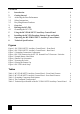
Contents Contents 1 2 2.1 2.2 2.3 3 4 4.
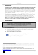
Introduction 1 Introduction Welcome to Kramer Electronics! Since 1981, Kramer Electronics has been providing a world of unique, creative, and affordable solutions to the vast range of problems that confront the video, audio, presentation, and broadcasting professional on a daily basis. In recent years, we have redesigned and upgraded most of our line, making the best even better! Our 1,000-plus different models now appear in 11 groups1 that are clearly defined by function.
Getting Started 2.
Overview 3 Overview The RC-53D is an auxiliary remote control panel for Master Room Controllers1 for control of A/V equipment in a room.
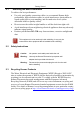
Defining the RC-53D Table 1: RC-53D K-NET™ Auxiliary Control Panel – Front Panel Features # Feature Function 1 1 SOURCE Buttons Group of four programmable, backlit buttons 2 Faceplate Screws Four screws connecting the faceplate to the Rear Box 3 “DISPLAY” and “SOURCE” Labels Programmable, 8 character, LCD displays on a blue background 4 DISPLAY Buttons Group of two programmable, backlit buttons 5 Maximum VOLUME LED Lights red, indicating maximum volume 6 VOLUME LEDs Light green, indicat
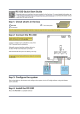
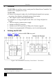
Defining the RC-53D 4.1 Grounding the RC-53D The grounding screw is used to earth the chassis of the unit to the building ground preventing static electricity from impacting the performance of the unit. Figure 3 and Table 3 define the grounding screw components. Table 3: Grounding Component Descriptions # Component Description 1 M3X6 screw 2 1/8" Toothed Lock Washer 3 M3 Ring Tongue Terminal Figure 3: Grounding Connection Components To ground the RC-53DLC: 1.
Using the RC-53D K-NET™ Auxiliary Control Panel 5 Using the RC-53D K-NET™ Auxiliary Control Panel The installation process is not detailed in this user manual.
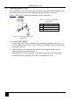
Installing the RC-53D Faceplate, Button Caps and Labels 6 Installing the RC-53D Faceplate, Button Caps and Labels This section describes how to install the faceplate, button caps and labels. Figure 5 illustrates a sample button label sheet. Figure 5: Sample Button Label Sheet To install the faceplate, button caps and labels: 1. Remove the required labels from the supplied button label sheet. 2. Hold the button cap so that it is oriented as shown in Figure 6 with the “wings” on the left and right sides.
Installing the RC-53D Faceplate, Button Caps and Labels 5. Retaining the orientation, place the six button caps on the buttons of the RC-53D. Figure 8: Placing the Button Cap 6. Remove the protective foils from both sides of the Perspex (acrylic glass) windows. 7. Remove the protective foils from both displays. 8. Place the faceplate on the RC-53D so that the four screw mounting holes are aligned. 9. Insert the four mounting screws and tighten with a screwdriver. 10. Install the volume control knob.
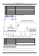
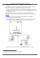
Operating the RC-53D K-NET™ Auxiliary Control Panel 7 Operating the RC-53D K-NET™ Auxiliary Control Panel In the following example1 (illustrated in Figure 9), the auxiliary control panel is labeled with specific functions and each button is programmed2 to perform several tasks3 as defined in Table 4.
Technical Specifications 8 Technical Specifications Table 5 defines the technical specifications. 1 Table 5: Technical Specifications of the RC-53D K-NET™ Auxiliary Control Panel PORTS: 2 K-NET on terminal block connectors; 1USB connector, 1 RS-232 on terminal block connector (factory use only) POWER SOURCE: 12V DC, 140mA over K-NET FUSE: 500mA, FSMD 1812 DIMENSIONS: For the USA: 11.4cm x 2.6cm x 11.4cm (4.49" x 1.02" x 4.49", W, D, H) For Europe: 15.2cm x 1.9cm x 8.6cm (5.98" x 0.75" x 3.
For the latest information on our products and a list of Kramer distributors, visit our Web site www.kramerelectronics.com, where updates to this user manual may be found. We welcome your questions, comments and feedback. Safety Warning: Disconnect the unit from the power supply before opening/servicing. Caution P/N: 2900- 000567 Rev: 4 Kramer Electronics, Ltd. Web site: www.kramerelectronics.com E-mail: info@kramerel.