
User's Manual

6
KRAMER ELECTRONICS LTD.
6
TYPICAL APPLICATIONS
6.1 Picture in Picture
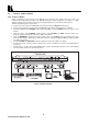
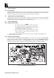
Figure 2 illustrates a typical set-up of the PIP-200: Two incoming video signals from video sources are
connected to the PIP-200 video inputs. The PIP-200 outputs the incoming signals to an acceptor in a "PIP"
(Picture in Picture) mode and the operator uses the programming keys to control the inserted pictures.
Perform the following steps (as necessary):
1. Connect two video sources to the PIP-200 input sockets and select Composite or YC format.
2. Connect Composite and/or YC acceptors to the PIP-200 output sockets (both outputs are available).
3. Activate the PIP function (INSERT), either immediately (ON), or via the WIPE function (see section 4.3 for
details).
4. Select the status of the FREEZE (inserted picture only), INVERT and SIZE (inserted picture only)
functions, using the front panel controls (see Table 1 for details).
5. Select if a BORDER is required around the inserted picture, or a MATTE (single color) background, using
the front panel controls. The border or matte color can be set using the Y, R-Y and B-Y front panel controls
(see Table 1 for details).
6. Use the COARSE and POSITION controls to locate the picture (see Table 1 for details).
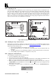
7. For RS-232 control, connect an RS-232 cable from your PC to the RS-232 connector of the PIP-200 (see
section 9.3).
8. Operate sources, acceptor, PC, and the PIP-200. The system is automatically detected, however full standard
conversion takes place only in the inserted picture.
Figure 2: Picture in Picture