Kramer Electronics, Ltd.
Contents Contents 1 2 3 3.1 3.2 3.3 4 4.1 4.2 4.3 5 5.1 5.2 5.3 6 6.1 6.
Contents Figures Figure 1: VP-128H Matrix Switcher Figure 2: VP-128H Local Control Panel Figure 3: VP-128H Front View with Front Panel Detached Figure 4: Connecting a PC without using a Null-modem Adapter Figure 5: RJ-45 PINOUT Figure 6: Connecting a VP-128H Matrix Switcher Figure 7: RC-1616 Remote Control Figure 8: RC-1616 Remote Control with its Front Panel Detached Figure 9: Connecting up to 512 RC-1616 Remote Control Units to a VP-128H 4 6 6 8 9 10 11 12 14 Tables Table 1: VP-128H Matrix Switcher Fro
Introduction 1 Introduction Welcome to Kramer Electronics (since 1981): a world of unique, creative and affordable solutions to the infinite range of problems that confront the video, audio and presentation professional on a daily basis. In recent years, we have redesigned and upgraded most of our line, making the best even better! Our 500-plus different models now appear in 8 Groups1, which are clearly defined by function.
Overview 3 Overview This section summarizes the: VP-128H Matrix Switcher, see section 3.1 RC-1616 Remote Control, see section 3.2 3.1 About the VP-128H The VP-128H is a true 12x8 matrix switcher for VGA / XGA signals that lets you simultaneously route any or all of the 12 inputs to any or all of the 8 outputs. The high performance VP-128H is rugged, easy to service1, and fits into one vertical space (1U) of a standard 19" rack.
Your VP-128H Matrix Switcher A passive two BNC sync loop - useful to ensure deterministic switching1 Two VP-128H units can be cascaded Control the VP-128H via the front panel buttons, or remotely: Via the 10 Base T network of RC-1616 panels2 or RS-232 serial commands transmitted by a touch screen system, PC, or other serial controller 3.2 About the RC-1616 The RC-1616 Remote Control is ideal for sophisticated control from various locations via the 10 Base T network.
Your VP-128H Matrix Switcher Figure 1: VP-128H Matrix Switcher 4 KRAMER: SIMPLE CREATIVE TECHNOLOGY
Your VP-128H Matrix Switcher Table 1: VP-128H Matrix Switcher Front Panel Features # 1 2 3 Feature Slide Action Latches 1 OUT Selector Buttons 3 IN Selector Buttons Function Fasten the front panel into the frame 2 Select the output to which the input is switched (from 1 to 8) Select the input to switch to the output (from 1 to 12) Table 2: VP-128H Matrix Switcher Rear Panel Features # 1 2 3 4 5 6 7 8 Feature RS-232 DB 9F Connector Slow Blow Fuse 4 Power Connector 10 Base T Port REF SYNC BNC Connector RE
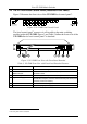
Your VP-128H Matrix Switcher 4.3 The VP-128H Local Control Panel (Detached Front Panel) Figure 2 illustrates the front view of the VP-128H local control panel1: Figure 2: VP-128H Local Control Panel1 The local control panel1 connects via a flat cable to the main switching module inside the VP-128H.
Connecting a VP-128H Matrix Switcher 5 Connecting a VP-128H Matrix Switcher You can control the VP-128H via: Its front (local) panel, see section 5.1 RS-232. For example, by connecting a PC via the null-modem adapter (when using the Kramer Control software or other controller) if control via RS-232 is required (see section 5.2) 10 Base T network (see section 5.3) The RC-1616 Remote Control (see section 6) 5.1 Connecting the VP-128H Matrix Switcher This section describes how to connect the VP-128H.
Connecting a VP-128H Matrix Switcher 5.
Connecting a VP-128H Matrix Switcher 5.
Connecting a VP-128H Matrix Switcher Figure 6 illustrates how to connect the VP-128H (without a remote control panel): Figure 6: Connecting a VP-128H Matrix Switcher 10 KRAMER: SIMPLE CREATIVE TECHNOLOGY
Your RC-1616 Remote Control 6 Your RC-1616 Remote Control The RC-1616 Remote Control1 can be used: With the front panel and rear panel intact, see section 6.1 With the RC-1616 front panel detached, see section 6.2 6.
Your RC-1616 Remote Control Table 7: RC-1616 Remote Control Rear Panel Features # Feature 1 9V DC 1A Connector 2 10 Base T Port Function +9V DC connector for powering the unit1 Connects to the 10 Base T network (used for remote panels) 6.2 The RC-1616 Front Panel Detached The detached RC-1616 front panel connects via a flat cable to the main switching module inside the RC-1616.
Your RC-1616 Remote Control 6.2.1 Setting the Dipswitches You need to set the dipswitches when using more than one RC-1616 remote panel.
Connecting a RC-1616 Remote Control 7 Connecting a RC-1616 Remote Control To connect a single RC-1616 Remote Control, do the following: 1. Connect the RC-1616 10 Base T port to the 10 Base T network, see section 5.3. 2. Detach the RC-1616 front panel by unfastening the slide action latches (see item 1 in Figure 7) and set the dipswitches (see section 6.2.1). 3. Connect the 9V DC 1A power adapter (wall transformer) to the 9 V DC socket and connect the transformer to the mains electricity.
Operating the VP-128H Matrix Switcher 8 Operating the VP-128H Matrix Switcher Operate your VP-128H via: The front panel buttons Remotely, from any one of up to 512 RC-1616 remote control panels via 10 Base T network and/or RS-232 serial commands transmitted by a touch screen system, PC, or other serial controller 8.1 Switching OUT-IN Combinations To switch an input to an output, do the following: 1. Press an OUTPUT SELECTOR1 button2. The button lights. 2. Press an INPUT SELECTOR3 button2.
Technical Specifications 9 Technical Specifications Table 11 includes the technical specifications: 1 Table 11: Technical Specifications of the VP-128H INPUTS: 12 analog red, green, blue signals - 0.7 Vpp / 75 ; H & V syncs, TTL level on HD15F connectors. The H and V channels are not TTL, they are linear OUTPUTS: 8 analog red, green, blue signals - 0.7 Vpp / 75 ; H & V syncs, TTL level on HD15F connectors. The H and V channels are not TTL, they are linear +/- 1.
Communication Protocols 10 Communication Protocols The VP-128H is compatible with the Kramer 2000 Protocol Supported Subset (see section 10.1), the Sierra Video Systems (SVS) RS-232 Compatible Protocol (see section 10.2), and the Generic Protocol Supported Subset (see section 10.3).
Communication Protocols 1st BYTE: Bit 7 – Defined as 0. D – “DESTINATION”: 0 - for sending information to the switchers; 1 - for sending to the PC (from the switcher). N5…N0 – “INSTRUCTION” The function that is to be performed by the switcher(s) is defined by the INSTRUCTION (6 bits). Similarly, if a function is performed via the machine’s keyboard, then these bits are set with the INSTRUCTION NO., which was performed. The instruction codes are defined according to the table below (INSTRUCTION NO.
Communication Protocols 10.1.1 Use of Kramer Machines A router may be represented via the Kramer protocol as a maximum of two machines. Based on the largest supported, 8 level switcher, the levels correspond accordingly: Level 1 2 3 4 5 6 7 8 Machine # 1 2 1 2 1 2 1 2 Function Video Video Audio Audio RGB Mute RGB Mute Audio Levels Audio Levels Parameter Terminology: Setups - Setup # 0 refers to the present switcher status. Setup # 1 and higher are the settings saved in the switchers memory, (i.e.
Communication Protocols “Switch Audio”: Switch Audio Crosspoint” Request: 0x02
Communication Protocols Setup Save”: Store / Delete Video Status Request: 0x03 Response: 0x43 Action: Saves or deletes a Setup The “Setup Save” command can be used to either save a setup based on the current switcher status, or to erase an existing setup.
Communication Protocols “Request Breakaway Setting” Request: 0x0b Response: 0x4b Action: Request breakaway switching setting The “Request Breakaway Settings” command is used to poll either the current breakaway configuration of the switcher, or a setup breakaway configuration. Specifying a value parameter of 0 requests current audio breakaway setting, and a value parameter of 1 requests the “follow” setting.
Communication Protocols “Store Audio Status” Request: 0x13 Response: 0x53 Action: Saves current audio status to specified setup The “Store Audio Status” is used to manage audio status in setups. Specifying a value of 0 for “value” will store the existing audio crosspoint status to a specified setup number. Specifying a value of 1 for “value” will delete the current audio information stored in the specified setup.
Communication Protocols “Request Audio Parameter” Request: 0x19 0x00 Response: 0x59 Action: Request an audio parameter of a specified input/output The “Request Audio Parameter” command is used to retrieve a parameter on an input or output. This command is precluded by an “Audio Parameter Settings” command, used to set further properties for this command.
Communication Protocols “Audio Parameter Settings” Request: 0x2A Response: None Action: Set Parameters for the next command The “Audio Parameter Settings” command is used to provide further information for the “Request Audio Parameter”, “Increase / Decrease Audio Parameter”, and “Set Audio Parameter” commands. Use the table below for input bit and value options.
Communication Protocols The “Execute Loaded Data” command is used in conjunction with the “Load Video Data” and “Load Audio Data” commands to commit loaded crosspoint information to the actual running status, or to a specified setup location. Setting the “setup #” parameter to 0 writes cached crosspoint information to running status.
Communication Protocols “Define Machine” Request: 0x3D Response: 0x7D Action: Gets machine physical configuration information The “Define Machine” command is used to request information about a specified machine’s physical configuration. See “command” and “options” below for specific configuration information.
Communication Protocols 1 10.2 Sierra Video Systems (SVS) RS-232 Compatible Protocol Target hardware application: the protocol is designed to be compatible with most existing applications that have driven the RS232 port on SVS routers. In some cases commands have been shortened and should be compatible with all SVS external drivers. The protocol only uses one command format to set crosspoints, on format to load setups and one for the structure of all reply messages. 10.2.
Communication Protocols Just before the router begins executing a command string, it sends a leader character (asterisks) to the host. As it executes the commands, some commands call for a response back to the host. Many of these strings contain characters within the string in order to make the message more human readable when viewed as raw data as would be the case when emulating a terminal. Software written to drive these routing switchers may ignore all spaces and characters in reply strings.
Communication Protocols would clear the matrix, and when finished, the following response would be generated: **OK!! This command only clears the crosspoint settings. Any data stored in the setup memory space or the values from the audio gains are not changed by this command.
Communication Protocols For other uses of the eight levels and other future features, either the first or second or both flag values will be non-zero.
Communication Protocols Level 1: Video crosspoint control Level 2: Audio crosspoint control Level 3: RGB Mute Level 4: Audio levels "X": Connect Crosspoint Request: **X!! out,in,lvl Response: **OK!! or an ‘Update’ message when updates are turned on. Action: Make a connection to an output on a level. The command "X" is used to request that a connection be made. It must be followed by an output number, a comma, an input number, a comma, and a level number(s).
Communication Protocols to the VERY NEXT vertical sync interval. If the number is 0, no delay occurs. The number must be no larger than 255. Note that this command will also delay the time at which the remaining command responses and the trailer character are returned to the host.
Communication Protocols "T": Trigger a Salvo Connect Sequence Request: **T reg!! Response: **OK!! Action: Trigger a list of connect commands stored in a salvo register. The command "T" is used to trigger a previously set up salvo (set using the "P" command above). It must be followed by a register letter from A to Z For example, the command: **TB D180 TC!! says to trigger salvo register B, delay 180 sync intervals, then trigger salvo register C.
Communication Protocols Changes in audio gains are NOT reported when Updates is turned on. Doing so would cause the router to send to the host long strings as panel operators turned up and down the volume. The query (?) command works for the A commands in the same way it operates on the X commands. When the configuration message flags are both set to 000, the action of these gain commands is upon the audio channel connected to hardware level 3 and effected via level 7.
Communication Protocols The default sequences across each line of the status message is: Output number – comma level 1 input number – comma . . . level 8 input number– comma At the beginning of the first line the router sends an asterisk and after the last line the router sends an exclamation !. "SA": Status Inquiry for Audio gains Request: **SA!! The command "SA" requests the status information for all audio gain values be returned to the host.
Communication Protocols "U": Automatic Output Change Reporting On/Off Request: **U!! { 0 | 1 | 2 } Response: (none) Action: Turn automatic output change reporting off or on. The command "U" turns on or off the automatic sending of output change reports. The command letter must be followed by either a number 0, 1, or 2 to specify the new automatic change report state, as follows: * 0: Automatic output change reporting is turned off.
Communication Protocols Is responded to with two messages that will report the status of output 6 and then output 5. **PA?!! Will cause a response string in the same format as used for an S command response, except the data reported is the contents of a setup register A rather than a the status of the current crosspoint configuration.
Communication Protocols 10.3 Generic Protocol Supported Subset This RS-232 communication protocol uses a default data rate of 9600 baud, 8 data bits, and 1 stop bit. 10.3.1 Use of Generic Machines A router may be represented via the Kramer protocol as a maximum of two machines. Based on the largest supported, 8 level switcher, the levels correspond accordingly: Level 1 2 3 4 10.3.
Communication Protocols “Audio Input Gain and Attenuation”: Request: *G Response: In Aud= Action: Sets audio gain to a positive value Request: *G Response: In Aud= Action: Sets audio gain to a negative value Request: |G Response: In Aud= Action: Increments audio gain by 1dB Request: |g Response: In Aud= Action: Decrements audio gain by 1dB The “Audio Input Gain and Att
Communication Protocols Global setups store and recall the current status of the switcher.
Communication Protocols Request:
Communication Protocols Command Meaning Command To Switcher Response From Switcher 1*3! Out03 In01 All Tie input 1 A&V to output 3 Output 3 tied to input 1 Command To Switcher Response From Switcher Q3*4!3*5!3*6! Out Multi In Multi All Command stack switches Multiple outputs switched “View Ties, Gain, Mutes, and Setups”: Request: V/v
LIMITED WARRANTY Kramer Electronics (hereafter Kramer) warrants this product free from defects in material and workmanship under the following terms. HOW LONG IS THE WARRANTY Labor and parts are warranted for seven years from the date of the first customer purchase. WHO IS PROTECTED? Only the first purchase customer may enforce this warranty. WHAT IS COVERED AND WHAT IS NOT COVERED Except as below, this warranty covers all defects in material or workmanship in this product.
For the latest information on our products and a list of Kramer distributors, visit our Web site: www.kramerelectronics.com, where updates to this user manual may be found. We welcome your questions, comments and feedback. Safety Warning: Disconnect the unit from the power supply before opening/servicing. Caution Kramer Electronics, Ltd. Web site: www.kramerelectronics.com E-mail: info@kramerel.