Kramer Electronics, Ltd.
Contents Contents 1 1.1 2 2.1 3 4 5 6 7 7.1 7.2 7.3 8 8.1 8.2 Introduction About the VP-727T Presentation Switcher Control Panel Getting Started Quick Start Overview Your VP-727T Presentation Switcher Control Panel Installing in a Desktop Installing on a Rack Connecting the VP-727T Connecting via RS-485 Connecting a PC (via RS-232) Setting the Machine # Operating the VP-727 using the VP-727T Using the VP-727T WIPE DIRECTION Buttons Making the Transition 1 1 1 1 2 3 7 9 10 11 12 12 13 13 14 8.2.1 8.2.
Introduction 1 Introduction Welcome to Kramer Electronics (since 1981): a world of unique, creative and affordable solutions to the infinite range of problems that confront the video, audio and presentation professional on a daily basis. In recent years, we have redesigned and upgraded most of our line, making the best even better! Our 500-plus different models now appear in 8 Groups1, which are clearly defined by function.
Overview 3 Overview The VP-727T is a unique presentation switcher control panel dedicated specifically to control the VP-727. It is ergonomically and aesthetically designed in a rugged, professional 19" 4U rack-mountable metal enclosure with the button layout in the style of the VP-727.
Your VP-727T Presentation Switcher Control Panel Enables special effect transitions between two sources via a robust T-bar (used for manual control of transition speeds).
Your VP-727T Presentation Switcher Control Panel Figure 1: VP-727T Presentation Switcher Control Panel 4 KRAMER: SIMPLE CREATIVE TECHNOLOGY
Your VP-727T Presentation Switcher Control Panel Table 1: VP-727T Presentation Switcher Control Panel Features 5 6 7 Feature LAMP Button MENU Button ENTER Button CONTROLLER ON Button Moves up one step (in the same level) in the OSD menu Toggles within each level 2 command / increases the range by one step 14 15 16 17 TRANSITION Buttons 13 3,5 8 9 OSD Button 10 FADE 2 Button 11 CUT 2 Button 12 Function Toggles the gooseneck lamp ON/OFF Displays the OSD Menu screen (or moves to the previous level in
Your VP-727T Presentation Switcher Control Panel Figure 2 and Table 2 define the side panel of the VP-727T: Figure 2: VP-727T Presentation Switcher Control Panel (Side Panel) Table 2: VP-727T Presentation Switcher Control Panel (Side Panel) Features TO VP-727 3-PIN Terminal Block # Feature 1 12V DC 2 RS-232 DB 9 Connector 3 MACH. # 4 4 MACH. # 3 5 MACH. # 2 6 MACH.
Installing in a Desktop 5 Installing in a Desktop This section describes how to install the VP-727T in a desktop1. To install the VP-727T in a desktop: 1. Cut an opening in the desktop—making the cut out on a wooden surface using a sabre saw or a keyhole saw—at the location where you want to insert the VP-727T. Figure 3 illustrates the cut out template (not to scale) defining the surface that you have to cut out to install your VP-727T. Figure 3: Cut Out Dimensions 2.
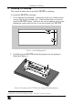
Installing in a Desktop 3. Insert the two mounting brackets through the bracket slits on both sides of the VP-727T unit (see Figure 5). Figure 5: Inserting the Mounting Brackets through the Bracket Slits 4. Be sure that the upper outer rim is situated parallel to the edge of the desktop. 5. Screw the mounting butterfly screws until they reach the desktop surface (from the underneath). 6. Tighten the locking butterfly screws to lock the mounting butterfly screws.
Installing on a Rack 6 Installing on a Rack This section describes what to do before installing on a rack and how to rack mount. Before Installing on a Rack Before installing on a rack, be sure that the environment is within the recommended range: Operating temperature range +5 to +45 Deg. Centigrade Operating humidity range 5 to 65% RHL, non-condensing Storage temperature range -20 to +70 Deg.
Connecting the VP-727T 7 Connecting the VP-727T To connect the VP-727T to up to four VP-727 machines, as the example in Figure 7 illustrates1, do the following2: 1. Connect the “TO VP-727” RS-485 3-PIN terminal block ports of the VP-727T, as follows (see section 7.1): MACH. # 1 to the RS-485 port of the VP-727 which will be recognized as machine # 1 MACH. # 2 to the RS-485 port of the VP-727 which will be recognized as machine # 2 MACH.
Connecting the VP-727T 7.
Connecting the VP-727T 7.2 Connecting a PC (via RS-232) You can connect a PC (or other controller) to the VP-727T via the RS-232 port for upgrading the firmware.
Operating the VP-727 using the VP-727T 8 Operating the VP-727 using the VP-727T For details of how to operate the VP-727 via the OSD Menu, LCD Display, ETHERNET, and/or RS-232, including using the TAKE button, refer to the VP-727 user manual1. For details of how to: Use the WIPE DIRECTION buttons, see section 8.1 Adjust the transition speed, see section 8.2 8.
Technical Specifications 8.2 Making the Transition You can make the transition in two ways: Manually, for each separate transition using the T-bar control lever1 Automatically, via the TAKE button, which implements the transition at the pace set by the SPEED2 knob 8.2.1 Making a Transition Manually To make the transition, manually: Slide the T-bar handle upwards3 or downwards4 8.2.
LIMITED WARRANTY Kramer Electronics (hereafter Kramer) warrants this product free from defects in material and workmanship under the following terms. HOW LONG IS THE WARRANTY Labor and parts are warranted for seven years from the date of the first customer purchase. WHO IS PROTECTED? Only the first purchase customer may enforce this warranty. WHAT IS COVERED AND WHAT IS NOT COVERED Except as below, this warranty covers all defects in material or workmanship in this product.
For the latest information on our products and a list of Kramer distributors, visit our Web site: www.kramerelectronics.com, where updates to this user manual may be found. We welcome your questions, comments and feedback. Safety Warning: Disconnect the unit from the power supply before opening/servicing. Caution Kramer Electronics, Ltd. Web site: www.kramerelectronics.com E-mail: info@kramerel.