Kramer Electronics, Ltd.
Contents Contents 1 2 2.1 3 3.1 4 5 6 6.1 Introduction Getting Started Quick Start Overview Terminology Used in this User Manual Your RC-80, RC-160 and RC-160L Remote Control Machines Installing in a Rack Connecting the Remote Control Machine Connecting the Remote Control Rear Panel 1 1 1 2 4 4 9 10 11 6.1.1 Connecting via RS-232 13 6.2 Controlling via ETHERNET 13 6.2.1 6.2.
Contents Figures Figure 1: RC-80 Remote Control Figure 2: RC-160 Remote Control Figure 3: RC-160L Remote Control Figure 4: Connecting the RC-160 Remote Control Figure 5: Connecting a Device without using a Null-modem Adapter Figure 6: Local Area Connection Properties Window Figure 7: Internet Protocol (TCP/IP) Properties Window Figure 8: Controlling via RS-485 Figure 9: RC-160 DIP-switches Figure 10: RC-160 Display Figure 11: The JTG Sender Window 5 6 7 12 13 14 14 16 16 18 23 Tables Table 1: Terminology
Introduction 1 Introduction Welcome to Kramer Electronics! Since 1981, Kramer Electronics has been providing a world of unique, creative, and affordable solutions to the vast range of problems that confront the video, audio, presentation, and broadcasting professional on a daily basis. In recent years, we have redesigned and upgraded most of our line, making the best even better! Our 1,000-plus different models now appear in 11 groups1 that are clearly defined by function.
Overview R e m o t e C o nt r o l S w it c h e r RS-232 R e m o t e C o n t r ol S w it c he r Rem ot e Cont r ol Rem ot e Cont r ol S w it c he r RS-232 S w it c h e r Rem ot e C ont r ol RS-23 2 ETHERNET 3 Overview The Kramer RC-80, RC-160 and RC-160L are an innovative series of master remote control units, designed for broadcasting studios and industrial applications.
Overview In particular, the Remote Control machines: Have an LCD display (for the RC-160 and RC-160L) or a bright 7-segment LED display (for the RC-80) Feature two RS-232 ports (IN and OUT), an RS-485 port, an Ethernet interface, and an IR receiver Include Audio-follow-video and breakaway options Have a TAKE button, for confirming actions Include a LOCK button to prevent tampering with the front panel Receive their power from a 12V DC source, making them ideal also for field operation Control the RC-80/RC-
Your RC-80, RC-160 and RC-160L Remote Control Machines 3.1 Terminology Used in this User Manual Table 1 defines some terms that are used in this user manual. Table 1: Terminology Used in this User Manual Term Definition The standard specification for ETHERNET that is maintained by the Institute of Electrical and Electronics Engineers (IEEE).
Your RC-80, RC-160 and RC-160L Remote Control Machines Figure 1: RC-80 Remote Control1 1 Item 9, which appears in Table 3 is not included in this machine 5
Your RC-80, RC-160 and RC-160L Remote Control Machines Figure 2: RC-160 Remote Control 6 KRAMER: SIMPLE CREATIVE TECHNOLOGY
Your RC-80, RC-160 and RC-160L Remote Control Machines Figure 3: RC-160L Remote Control 7
Your RC-80, RC-160 and RC-160L Remote Control Machines Table 2: Front Panel RC-80/RC-160/RC-160L Remote Control Features # Feature Function RC-80 RC-160 RC-160L 1 IR Receiver 2 LOCK Button 3 OUT / OUTPUT SELECTOR Buttons1 Select the output to which the input is to be routed Select the input to switch to the output 5 IN / INPUT SELECTOR 1 Buttons VIDEO Button 6 AUDIO Button When button illuminates, actions relate to audio .
Installing in a Rack 5 Installing in a Rack This section describes what to do before installing in a rack and how to rack mount.
Connecting the Remote Control Machine 6 Connecting the Remote Control Machine The RC-160 Remote Control1 can be connected in several configurations, as defined in Table 4: Table 4: Remote Control Configurations 1 2 3 4 5 The Remote 2 Control is connected to the switcher via the 3 RS-232 ports Two or more Remote Control machines are connected in series to the switcher via the 3 RS-232 ports R e m o t e C o nt r o l RS-232 R e m o t e C o nt r o l R e m o t e C o nt r o l S w it c her RS-232 A P
Connecting the Remote Control Machine This section describes how to connect: The Remote Control rear panel (see section 6.1) A switcher, an additional controller and/or a PC via the RS-232 ports (see section 6.1.1) A PC via the Ethernet (see section 6.2) and configure the Ethernet port (see section 6.3) Several Remote Control machines via RS-485 (see section 6.4) To set the DIP-switches, see section 6.5 6.
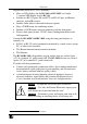
Connecting the Remote Control Machine When controlling via RS-232, set the machine # to 1 on each machine (the controllers and the switcher) The STATUS display on both the remote control panels illuminate and after a few seconds will show the status of the connected switcher. If a “ ” message appears, refer to section 7.1.
Connecting the Remote Control Machine 6.1.
Connecting the Remote Control Machine 3. Right-click Local Area Connection Properties. 4. Select Properties. The Local Area Connection Properties window appears. 5. Select the Internet Protocol (TCP/IP) and click the Properties Button (see Figure 6). Figure 6: Local Area Connection Properties Window 6. Select Use the following IP address, and fill in the details as shown in Figure 7. 7. Click OK. Figure 7: Internet Protocol (TCP/IP) Properties Window 6.2.
Connecting the Remote Control Machine 6.3 Configuring the Ethernet Port After connecting the Ethernet port, you have to install and configure it. For detailed instructions on how to install and configure your Ethernet port, see the “Ethernet Configuration (FC-11) guide.pdf” on our Web site: http://www.kramerelectronics.com 6.4 Controlling via RS-485 You can connect several Remote Control units and a Kramer switcher, via the RS-485 port.
Connecting the Remote Control Machine OFF ON 1 2 3 4 5 6 7 8 OFF ON 1 2 3 4 5 6 7 8 RS-485 PINOUT G _ B + A K r am er S w it c he r Figure 8: Controlling via RS-485 6.5 Setting the DIP-switches By default, all DIP-switches are set to OFF.
Connecting the Remote Control Machine Table 6 defines the Machine # DIP-switch settings: Table 6: Machine # DIP-switch Settings Mach. # 1 2 3 4 5 6 7 8 DIP 1 ON OFF ON OFF ON OFF ON OFF DIP 2 OFF ON ON OFF OFF ON ON OFF DIP 3 OFF OFF OFF ON ON ON ON OFF DIP 4 OFF OFF OFF OFF OFF OFF OFF ON Mach.
Operating the Remote Control Machine 7 Operating the Remote Control Machine This section describes how to: Read the display (see section 7.1) and view the current status (see section 7.1.1) Switch OUT-IN combinations (see 7.2) Confirm settings (see section 7.3) Choose the audio-follow-video or the breakaway feature (see section 7.4) Lock the front panel (see section 7.5) 7.
Operating the Remote Control Machine 7.2 Switching OUT-IN Combinations To operate the machine, enter the inputs and outputs to be connected: For matrices, use both the IN and the OUT keys For switchers (only one output) use only the IN keys You can switch an input to an output in the At Once mode1 or the Confirm mode1. To switch a video/audio input to a video/audio output in the At Once mode2, do the following: 1. Press an OUT button.
Operating the Remote Control Machine 7.3 Confirming Settings You can choose to work in the At Once or the Confirm mode.
Operating the Remote Control Machine 7.4 Choosing the Audio-Follow-Video or Breakaway Option You can switch stereo audio signals in one of two ways, either: Audio-follow-video (AFV), in which all operations relate to both the video and the audio channels; or Breakaway, in which video and audio channels switch independently 7.4.1 Setting the Audio-Follow-Video Option To set the Audio-follow-video (AFV) option, press the AUDIO and VIDEO buttons1 simultaneously.
Flash Memory Upgrade 8 Flash Memory Upgrade The RC-160 firmware is located in FLASH memory, which lets you upgrade to the latest Kramer firmware version in minutes! The process involves: Downloading from the Internet (see section 8.1) Connecting the PC to the RS-232 IN port (see section 8.2) Upgrading Firmware (see section 8.3) 8.1 Downloading from the Internet You can download the up-to-date file1 from the Internet. To do so: 1. Go to our Web site at http://www.kramerelectronics.
Flash Memory Upgrade 8.3 Upgrading Firmware Follow these steps to upgrade the firmware: 1. Double click the JTG-Sender desktop icon. The JTG-Sender window appears (see Figure 11). Figure 11: The JTG Sender Window 2. Select the required COM Port1. 3. Press the File button to select the .jtg firmware file included in the package. 4. Press the Send button to download the file. The Send button lights green. 5. Wait until downloading is completed and the green Send button turns off.
Technical Specifications 9 Technical Specifications Table 7 includes the technical specifications: 1 Table 7: Technical Specifications of the RC-80, RC-160 and RC-160L INPUTS/OUTPUTS: 2 RS-232 9-pin D-sub IN/OUT connectors 1 RS-485 connector on detachable terminal blocks 1 Ethernet CAT 5 port 2 CONTROLS: Front panel buttons, RS-232, RS-485, Ethernet and IR, LCD contrast trimmer POWER SOURCE: RC-80: 12V DC, 200mA RC-160/RC-160L: 12V DC, 130mA RC-80, RC-160: 19-inch (W), 2-inch (D) 1U (H) rack-mountable DI
Kramer Protocol 2000 10 Kramer Protocol 20001 The RC-80, RC-160, and RC-160L communicate with machines controlled using Protocol 2000 (version 0.46) (below). This communication protocol uses four bytes of information as defined below. For RS-232, a null-modem connection between the machine and controller is used. The default data rate for RS-232/RS-485 is 9600 baud, with no parity, 8 data bits and 1 stop bit.
Kramer Protocol 2000 For a single machine controlled via the serial port, always set M4…M0 = 1, and make sure that the machine itself is configured as MACHINE NUMBER = 1. Table 9: Instruction Codes for Protocol 2000 Note: All values in the table are decimal, unless otherwise stated.
Kramer Protocol 2000 INSTRUCTION # 15 16 17 18 19 20 21 DEFINITION FOR SPECIFIC INSTRUCTION DESCRIPTION INPUT NOTE OUTPUT REQUEST WHETHER SETUP IS DEFINED / VALID INPUT IS DETECTED ERROR / BUSY SETUP # or Input # 0 - for checking if setup is defined 8 1 - for checking if input is valid For invalid / valid input (i.e.
Kramer Protocol 2000 INSTRUCTION # DEFINITION FOR SPECIFIC INSTRUCTION DESCRIPTION INPUT NOTE OUTPUT 42 AUDIO PARAMETER SETTINGS FOR INSTRUCTIONS 22, 24, 25 INPUT Bit: I0 - 0=input; 1=output I1 - Left I2 - Right 0 - Gain 1 - Bass 2 - Treble 3 - Midrange 24 43 VIDEO PARAMETER SETTINGS FOR INSTRUCTIONS 21, 23, 26 1 – Input 2 – Output 24 56 CHANGE TO ASCII 0 57 SET AUTO-SAVE 58 59 EXECUTE LOADED DATA LOAD VIDEO DATA I3 - no save I4 - auto-save Set as 0, or as SETUP #.
Kramer Protocol 2000 NOTE 5 – For the OUTPUT byte set as 6, the VIS source is the input selected using the OUTPUT byte. Similarly, for the OUTPUT byte set as 7, the VIS source is the output selected using the OUTPUT byte. Note also, that on some machines the sync source is not software selectable, but is selected using switches, jumpers, etc! NOTE 6 – If INPUT is set to 127 for these instructions, then, if the function is defined on this machine, it replies with OUTPUT=1.
Kramer Protocol 2000 NOTE 18 – Delayed execution allows switching after a delay dictated by RS-232. To do this, the user sends instruction 7 with the “Set for delayed switch” option (64dec) before sending the switch command (instruction 1) or pressing via front panel. The switch is not executed (unless timed-out) until the “Execute delayed switch” code is sent, or the “Set for delayed switch” code is sent again.
LIMITED WARRANTY Kramer Electronics (hereafter Kramer) warrants this product free from defects in material and workmanship under the following terms. HOW LONG IS THE WARRANTY Labor and parts are warranted for seven years from the date of the first customer purchase. WHO IS PROTECTED? Only the first purchase customer may enforce this warranty. WHAT IS COVERED AND WHAT IS NOT COVERED Except as below, this warranty covers all defects in material or workmanship in this product.
For the latest information on our products and a list of Kramer distributors, visit our Web site: www.kramerelectronics.com, where updates to this user manual may be found. We welcome your questions, comments and feedback. Safety Warning: Disconnect the unit from the power supply before opening/servicing. Caution Kramer Electronics, Ltd. Web site: www.kramerelectronics.com E-mail: info@kramerel.