KRAMER ELECTRONICS LTD. USER GUIDE MODEL: Kramer Site-CTRL Room Controller Guide Software Version 2.0.0.x Intended for Kramer Technical Personnel or External System Integrators. To check that you have the latest version, go to the DOWNLOADS section of our Web site at: http://www.kramerelectronics.com/support/downloads.
Contents 1 Introduction 1 2 2.1 2.2 2.3 3 3.1 3.2 Site-CTRL System requirements Install the software Loading the Software The Site-CTRL Main Window The Site-CTRL Menu Quick Access Items 2 2 2 4 5 5 5 4 4.1 4.2 4.3 The Room List Tab Adding Several Rooms At Once Saving the Project Scheduled Tasks 6 10 11 13 5 5.
1 Introduction Welcome to Kramer Electronics! Since 1981, Kramer Electronics has been providing a world of unique, creative, and affordable solutions to the vast range of problems that confront video, audio, presentation, and broadcasting professionals on a daily basis.
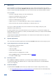
2 Site-CTRL Kramer Site-CTRL is a powerful A/V assets management tool. It offers real-time monitoring and control of Kramer Master controllers (such as the Kramer RC-74DL and SL-12) installed in an A/V site and the A/V equipment connected to them. The Kramer Site-CTRL downloadable version can monitor and control up to 100 Kramer Master controllers.
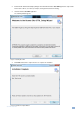
2. Extract the file “Kramer Site-Ctrl.zip” package, which includes the Kramer Site-CTRL application setup and the Kramer device drivers, to a folder (for example, C:\Program Files\Kramer K-Config). 3. Install the Kramer Site-CTRL application. The following window appears: Figure 1: Installing Site-CTRL 4. Click Next and follow the setup instructions to complete the installation.
2.3 Loading the Software After installation, you can click the Site-CTRL icon on your desktop or you click the START icon on your desktop. You will be prompted to enter your user name and password to login (the factory default password is admin. The password can be changed via the Settings tab): For the administrator: For the user: Figure 3: Admin and User Login i Logging as ADMIN will give you the ability to add or remove monitored rooms and setup the different Site-CTRL features.
3 The Site-CTRL Main Window The Site-CTRL main window includes the controlled rooms list (described in Section 4), an easy-to-use menu, quick access icons, a Scheduled Tasks button and a Logout button. 3.1 The Site-CTRL Menu The Site-CTRL menu includes the File and the About menus. The File menu is accessible to the administrator only and the About menu is also accessible to the user.
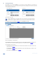
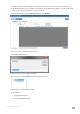
4 The Room List Tab The Room List tab displays the status of the Kramer room controllers in a summarized layout, and lets you identify the room by its IP number, name (for example, Science Lab 1), or description. From this screen the user can also monitor the status of the main display (on, standby and so on), monitor the projector lamp hours of the main display (per room) and perform routine procedures such as initiating a simple ON/OFF macro (via Web Access).
The "New Location" can list several Sites and each site can control several rooms. For example, a University can include different faculties (sites) each with several classrooms and/or labs and other facilities. You can rename "New Location" to suit your needs and add sites and rooms to the list.
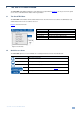
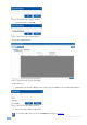
Figure 10: The Room List Tab – Typing the Site Name 3. Type the Site name and click OK. Figure 11: The Room List Tab – Typing the Site Name The new site is added to the list: Figure 12: The Room List Tab – New Site Name Added To add a new room: 1. Right-click the Site (Faculty of Medicine in this example) and select Add Room. The following window appears: Figure 13: The Room List Tab – Adding a New Room 2.
Figure 14: The Room List Tab – New Room Details 3. Click Add. Figure 15: The Room List Tab – New Room Added The new room appears under the Site list (Faculty of Medicine in this example) and as a line in the room table. In the same way you can add other controlled rooms and create sites with lists of controlled rooms.
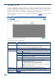
Each room line displays the status of the room and details the actions that can be taken: 4.1 Msg – Switches to the Event Log tab and filters the log list according to the device’s Web pressed button (meaning – shows events of a single device) Web – Open the device’s Web page in the PC’s default browser On/Off – executes All On or All Off Password – when the device’s security is on, the Web page’s login screen requires a password.
4.2 Saving the Project Once the list is ready, you can save it.
Figure 21: Saving a new project – Saving the New Project to a Folder If this is the first time you are saving the project, the following message appears: Figure 22: Saving a new project – Creating the New Project Click the Yes button.
4.3 Scheduled Tasks You can create scheduled tasks via the three buttons located on the lower left side of the Room List tab: Update Time –schedule a time update to a device list, see Section 4.3.1 Update Firmware – schedule several firmware updates to a group of selected devices, see Section 4.3.2 Update Configuration – schedule a configuration update to a group of devices, see Section 4.3.
Recurrence pattern on the left side lets you choose a daily, weekly or monthly pattern. On the right side you can fill in the start and end date and recurrence of the task. The Daily schedule is illustrated in Figure 25 and Figure 26. For a daily schedule check Daily: Figure 25: Scheduling – Daily Pattern Initially, the daily schedule is set to a one-time occurrence (Repeat every is set to 0). If you need the task to occur more than once, you can set Repeat every to any number of days required.
Figure 28: Scheduling – Monthly Pattern In the monthly schedule, check the months, the days in the month or the week in the month and the day. You can set an end date by checking the Ends checkbox.
The lower side of the window shows a summary of the setups. For example, a Monthly setup will show this: Figure 30: Scheduling – Summary 4.3.1 Update Time The Update Time button lets you schedule a time update for devices that are checked in the Room List. To update the time, do the following: 1. Check the relevant rooms in the room list. 2. Click the Update Time button. The scheduling window appears (see Figure 23): 3. Make sure the setup is correct and then click Add.
Figure 32: Update Time – Show Log Button 4.3.2 Update Firmware You can schedule a firmware update to one or several devices in selected rooms all at once. To update the firmware: 1. In the Room List tab, select the rooms to which the firmware update is relevant. 2. Click the Update Firmware button. The following window appears: Figure 33: Update Firmware – Selecting the Firmware Upgrade File 3. Select the firmware upgrade file and click Open. The Scheduling window appears.
Figure 34: Update Firmware – the Scheduling Window 4. Make sure the setup is correct and then click Add. The time update is added to the scheduled tasks list. i Note that you can select more than one file to update (see Figure 35). The system searches all the master controllers + auxiliary devices and sends each updated firmware file to its designated device. To do this you need to move all the relevant firmware files to one folder and select them all.
4.3.3 Update Configuration You can update the room controllers of identically configured rooms in the room list all at once via the Update Configuration button. The room controller configuration file used is created via the K-Config software through the Export Configuration item in the File menu. To update a configuration, do the following: 1. Check the list of the relevant rooms. 2. Click the Update Configuration button.
5 The Settings Tab The settings tab is mainly intended for the administrator. Logging as a user will only let you the language (English or Russian) and check the Write Minor Log Events box. The Settings tab lets you set an e-mail notification in case of a defined event for a certain room or certain type of problem, and set the Handshake interval between the different rooms. Figure 37 shows the Settings tab.
Figure 38: Email Notification – Adding an e-mail Address 2. Type in the e-mail address and click OK. The address appears in the Email Notification area: Figure 39: Email Notification – the e-mail Address Added i 3. You can always change the email address by clicking Edit>> in the Email cell. To set the rooms (IP numbers) that are relevant to this e-mail recipient, click Edit>> in the IP cell. The following window appears: Figure 40: Email Notification – the Select IP Window 4.
6. To set the groups of alerts (Alert Groups) that are relevant to this e-mail recipient, click Edit>> in the Alert Groups cell. The following window appears: 7. Check the alert Statuses that are relevant to this recipient or check Select All/Select None. Figure 41: Email Notification – The Select Alert Group Window 8. Click OK. 9. To set the type of alerts (Alert Statuses) that are relevant to this e-mail recipient, click Edit>> in the Alert Types cell. 10.
Figure 43: Email Notification – The Settings Tab with email i After adding the details you have to click the Apply button to save the mail settings, otherwise data will be lost.
Figure 46: Email Notification – Power notification email For example, the power notification state will appear under the Main Display Status column in the Room List tab: Figure 47: Email Notification – Power is Off in Room List Tab 24 Site-CTRL - The Settings Tab
6 The Event Log Tab The Event Log tab lists the controlled room events. The Filter area lets you filter the information displayed.
Figure 49 illustrates an operating Event Log tab Figure 49: The Event Log Tab in Operation 26 Site-CTRL - The Event Log Tab