K R A ME R E LE CT R O N IC S L TD .
Contents 1 Introduction 1 2 2.1 2.2 2.3 3 3.1 Getting Started Achieving the Best Performance Safety Instructions Recycling Kramer Products Overview Defining the SL-10 Master Room Controller 2 2 3 3 4 5 4 4.1 4.2 4.3 4.4 4.
1 Introduction Welcome to Kramer Electronics! Since 1981, Kramer Electronics has been providing a world of unique, creative, and affordable solutions to the vast range of problems that confront video, audio, presentation, and broadcasting professionals on a daily basis.
2 Getting Started We recommend that you: Unpack the equipment carefully and save the original box and packaging materials for possible future shipment Review the contents of this user manual i 2.1 Go to http://www.kramerelectronics.com/support/product_downloads.asp to check for up-to-date user manuals, application programs, and to check if firmware upgrades are available (where appropriate).
2.2 Safety Instructions ! 2.3 Caution: There are no operator serviceable parts inside the unit Warning: Use only the Kramer Electronics input power wall adapter that is provided with the unit Warning: Disconnect the power and unplug the unit from the wall before installing Recycling Kramer Products The Waste Electrical and Electronic Equipment (WEEE) Directive 2002/96/EC aims to reduce the amount of WEEE sent for disposal to landfill or incineration by requiring it to be collected and recycled.
3 Overview The SL-10 is a highly versatile controller that acts as an all-in-one control processor for control of A/V equipment—especially projectors and associated equipment—in any room (such as classrooms, boardrooms, or auditoriums). It streamlines operations and simplifies control by integrating audio, video, and computer-video sources into a centralized system.
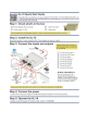
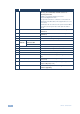
3.1 Defining the SL-10 Master Room Controller This section defines the SL-10. Figure 1: SL-10 Master Room Controller # Feature Function 1 ETHERNET RJ-45 Connector Connects to the PC or other serial controller through computer networking LAN to control several AV products over Ethernet 2 DEFAULT Recessed Pushbutton Press to reset to factory default definitions: IP number 192.168.1.39, Mask – 255.255.0.0 Gateway – 0.0.0.
# 8 Feature Function K-NET Connector PIN GND is for the Ground connection; PIN B (-) and PIN A (+) are for RS-485, and PIN +12V is for powering other units K-NET is a proprietary Kramer protocol for interconnecting Kramer units The ground connection is sometimes connected to the shield of the RS-485 cable (in most applications, it is not connected) Note that the SL-10 cannot receive power via the K-NET connector, but can power other units (but not another SL-10) 9 RS-485 TERM Switch Slides down for R
4 Connecting the SL-10 i Always switch off the power to each device before connecting it to your SL-10. After connecting your SL-10, connect its power and then switch on the power to each device. To connect the SL-10 as illustrated in the example in Figure 2: 1. Connect the RELAY terminal block connectors as follows: Connect RELAY 1 and 2 to the projector lift Connect RELAY 3 and 4 to the screen Connect RELAY 5 to the lighting system 2.
8. Connect the K-NET port to any RC device with K-NET. Figure 2: Connecting the SL-10 Master Room Controller 4.1 Using the RC-4 IR Transmitter You can use the optional RC-4 IR transmitter as an auxiliary control panel and initiate configured control triggers—refer to the K-Config guide—via the built in IR receiver on the front panel, or instead, via an optional external wired IR receiver, which exists in several cable lengths (shown in Figure 2). 4.
Figure 3: RS-232 Connection 4.3 Connecting the RS-485 Interface To connect an AV device to the SL-10 using the RS-485 port, connect the RS-485 port on your device to the RS-485 terminal block on the rear panel of the SL-10 as shown in Figure 4: Figure 4: RS-485 Connection 4.4 Connecting the Ethernet Port The Ethernet connection of the SL-10 allows you to perform all control functions of the SL-10 over the Internet using a PC running the Kramer Site-CTRL control program.
After connecting the Ethernet port, you have to install and configure it. For detailed instructions on how to install and configure your Ethernet port, see the K-Config Guide. Available for download at the Kramer Web site: www.kramerelectronics.com. 4.5 Connecting the K-NET Port The K-NET port is wired as shown in Figure 5.
5 Operating the SL-10 You can operate your SL-10 using: An RC family remote controller: To operate your device using an RC remote controller, see the Kramer K-Config Guide Available for download at the Kramer Web site: www.kramerelectronics.
6 Technical Specifications INPUTS: 2 RS-232, RS-485, 2 GPI/O and K-NET on terminal block connectors; Ethernet on an RJ-45 connector; 1 infrared built-in receiver, 1 infrared on a 3.5mm mini jack connector; 1 USB for programming OUTPUTS: 3 infrared, 5 relays (36V AC or DC, 2A, 60VAC maximum on non-inductive load) and 2 GPI/O on terminal block connectors DEFAULT IP SETTINGS: IP number − 192.168.1.39; Mask – 255.255.0.0; Gateway – 0.0.0.
For the latest information on our products and a list of Kramer distributors, visit our Web site where updates to this user manual may be found. We welcome your questions, comments, and feedback. Web site: www.kramerelectronics.com E-mail: info@kramerel.