Kramer Electronics, Ltd.
Contents Contents 1 2 2.1 3 4 5 6 6.1 6.2 7 7.1 7.2 7.
Introduction 1 Introduction Welcome to Kramer Electronics! Since 1981, Kramer Electronics has been providing a world of unique, creative, and affordable solutions to the vast range of problems that confront the video, audio, presentation, and broadcasting professional on a daily basis. In recent years, we have redesigned and upgraded most of our line, making the best even better! Our 1,000-plus different models now appear in 11 groups 1 that are clearly defined by function.
Getting Started 2.1 Quick Start This quick start chart summarizes the basic setup and operation steps.
Overview 3 Overview The Kramer SP-12HD is a multi-standard/multi-format, broadcast-quality video processor and ProcAmp. It is a universal single-box solution for all your video processing requirements. The SP-12HD HD-SDI Processor features the following: • Inputs: composite video, s-Video, component video (YUV), SD/HD-SDI • Outputs 1: composite video, s-Video, component video (YUV), SD/HD-SDI (2 outputs), “Before/after” split-screen • Input Video Standards: composite PAL-B, PAL-M, PAL-N, NTSC-3.
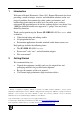
Your SP-12HD HD-SDI Processor To achieve the best performance: • Use only good quality connection cables 1 to avoid interference, deterioration in signal quality due to poor matching, and elevated noise levels (often associated with low quality cables). • Avoid interference from neighboring electrical appliances that may adversely influence signal quality and position your Kramer SP-12HD away from moisture, excessive sunlight and dust 4 Your SP-12HD HD-SDI Processor Figure 1 and Table 1 define the unit.
Your SP-12HD HD-SDI Processor Figure 1: SP-12HD HD-SDI Processor Functions 5
Your SP-12HD HD-SDI Processor Table 1: SP-12HD HD-SDI Processor Functions # 1 Feature Scanning Format LEDs 2 Field/Frame Rate LEDs 3 4 5 Active Lines Per Frame LEDs INPUT Selector Button AUTO Button 6 7 INPUT LEDs SPLITTER Button 8 V-SHARP Button 9 H-SHARP Button 10 BRIGHT Button 11 CONTRAST Button 12 V-SHIFT Button 13 H-SHIFT Button 14 GAIN Button 15 Y/GREEN Button 16 17 COLOR Button U/BLUE Button 18 HUE Button Function i = interlaced p = progressive PsF = progressive segmented
Your SP-12HD HD-SDI Processor V/RED Button 20 COLOR SPACE Button 21 YUV/RGB LEDs 22 23 24 25 26 27 STORE Button RECALL Button 7-segment Display - Button + Button PANEL LOCK Button 30 31 32 33 34 35 36 37 38 39 40 41 42 43 44 45 46 47 48 Y/C 4-pin Connector Y BNC Connector Function 1 2 Press the V /RED button and adjust using the + and – buttons, when COLOR SPACE button is activated Press to select the color space of color control; if the COLOR SPACE button doesn’t illuminate, color control is disab
Installing the SP-12HD HD-SDI Processor in a Rack 5 Installing the SP-12HD HD-SDI Processor in a Rack This section describes how to install the SP-12HD in a rack.
Connecting the SP-12HD HD-SDI Processor 6 Connecting the SP-12HD HD-SDI Processor You can use your SP-12HD to convert 1 composite video, s-Video, component video (YUV), or SDI signals to composite video (PAL or NTSC), s-Video, component video (YUV) and 2 SDI, as well as to a “Before/after” split-screen, as the example illustrates in Figure 2. To connect 3 the SP-12HD Digital Video Processor, do the following 4: 1.
Connecting the SP-12HD HD-SDI Processor Figure 2: Connecting the SP-12HD HD-SDI Processor 10 KRAMER: SIMPLE CREATIVE TECHNOLOGY
Connecting the SP-12HD HD-SDI Processor 6.1 Connecting the RS-232 Port Figure 3: Connecting the RS-232 Port 6.2 Setting the DIP-Switches Configure the SP-12HD unit by setting the 8 DIP-switches, as defined in Table 2 and Table 3: Table 2: DIP-Switch Settings DIP-Switch PEDESTAL Set as follows: ON for pedestal of output signal (7.5 IRE offset selection for NTSC); OFF for no pedestal 2 Input sync bi-level or tri-level (HDTV) Active only in HDTV mode: ON for bi-level input sync, OFF for tri-level.
Operating the SP-12HD HD-SDI Processor Table 3: Test Signals 1 # TEST-4 OFF TEST-5 OFF TEST-6 OFF Test Signal Normal operating mode, no test active 2 ON OFF OFF RAMP 100% 3 OFF ON OFF Y-SWEEP (5.8MHz – SDTV, 11.6MHz – EDTV, 30MHz – HDTV ) 4 OFF OFF ON COLOR BARS 100% 5 ON ON OFF SPLIT BARS 100% 6 OFF ON ON PULSE 2T and BAR 7 8 ON ON OFF ON ON ON C-SWEEP (1.
Operating the SP-12HD HD-SDI Processor • • • • • • 7.1 display shows the current level (in digits).
Operating the SP-12HD HD-SDI Processor • • 7.2 Press the RECALL button and then select the appropriate # (that corresponds to the setup #) by pressing the + and – buttons (the selected setup is recalled) Then press RECALL button one more time Locking the Front Panel To prevent changing the settings accidentally or tampering with the front panel, lock your SP-12HD. Unlocking releases the protection mechanism.
Technical Specifications 8 Technical Specifications The SP-12HD technical specifications are shown in Table 4: 1 Table 4: Technical Specifications of the SP-12HD HD-SDI Processor INPUTS: 1 composite video: 1Vpp/75Ω on a BNC connector; 1 Y/C: 1Vpp/75Ω (Y), 0.3Vpp/75Ω (C) on a 4-pin connector; 1 component: Y/R-Y/B-Y (1Vpp/0.7Vpp/0.7Vpp)/75Ω on BNC connectors; 1 SDI: SMPTE-259M, SMPTE-292M, SMPTE-344M, ITU-R BT.
Communication Protocol 9 Communication Protocol RS-232 communication between the SP-12HD and the PC is performed using this protocol (VER 0.1). The protocol 1 uses four bytes of information, and transmission settings are 9600 baud, no parity, 8 data bits and 1 stop bit.
Communication Protocol Table 6: Instruction Set # INSTRUCTION I5 I4 I3 I2 I1 I0 0 16 Reset Error 0 0 0 1 0 0 0 0 0 0 0 0 32 33 Read front-panel switch data Write front-panel switch data 1 1 0 0 0 0 0 0 0 0 0 1 34 Recall 1 0 0 0 1 0 35 61 Store Identify machine 1 1 0 1 0 1 0 1 1 0 1 1 DESCRIPTION OF INSTRUCTIONS Inst No Instruction name Data Number Data Name Extended 0 RESET 0 Initialize machine 0 When the machine is initialized, it sends the RESET code (DATA
Communication Protocol SWITCH NUMBER AND SWITCH VALUE PARAMETERS Switch Number Description Switch Value 0 1 INPUT FORMAT INPUT_STAND_YUV/SDI (for input format YUV or SDI) Description 0 CV (default) 1 YC 2 YUV 3 SDI 0 AUTO (default)(read D=24 for STANDARD_AUTO) 1-480i/60 11-1080p/23.9 2-480p/60 12-1080p/24 3-576i/50 13-1080p/25 4-576p/50 14-1080p/29.9 5-720p/50 15-1080p/30 6-720p/59.9 16-1080psf/23.9 7-720p/60 17-1080psf/24 8-1080i/50 18-1080psf/25 9-1080i/59.9 19-1080psf/29.
Communication Protocol Switch Number Description Switch Value Description 23 TEST 0-7 Read only - switch controlled 0 - Test off (default) 1 - Color bars 100% 2 - Y-sweep 3 - Pulse 2T and bar 4 - Ramp 100% 5 - C-sweep 6 - Split bars 100% 7 - Grid 24 ACTIV_AUTO_STAND status of standard auto-identification, read only 0 - 19 In case of forced input standard value "E" corresponds to this standard.
LIMITED WARRANTY Kramer Electronics (hereafter Kramer) warrants this product free from defects in material and workmanship under the following terms. HOW LONG IS THE WARRANTY Labor and parts are warranted for seven years from the date of the first customer purchase. WHO IS PROTECTED? Only the first purchase customer may enforce this warranty. WHAT IS COVERED AND WHAT IS NOT COVERED Except as below, this warranty covers all defects in material or workmanship in this product.
For the latest information on our products and a list of Kramer distributors, visit our Web site: www.kramerelectronics.com where updates to this user manual may be found. We welcome your questions, comments and feedback. Safety Warning: Disconnect the unit from the power supply before opening/servicing. Caution Kramer Electronics, Ltd. Web site: www.kramerelectronics.com E-mail: info@kramerel.